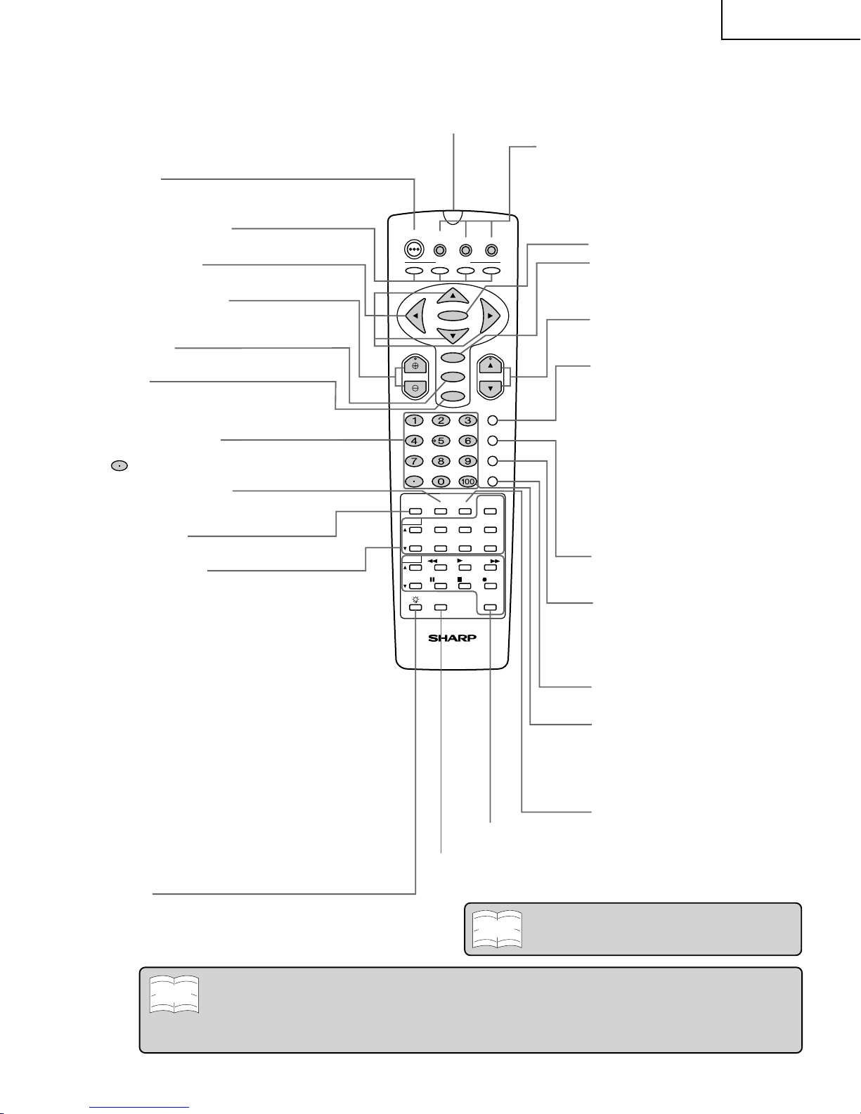
DTV
STB
POWER
TV
A
ENTER
MENU
VOL CH
AV MODE
MUTE
INPUT
ANT-A/B
DISPLAY
FLASHBACK
ENT.
CC
PLAY FF
POP
REW
PAUSE
STOP REC
SEARCH
SELECT
DDFC
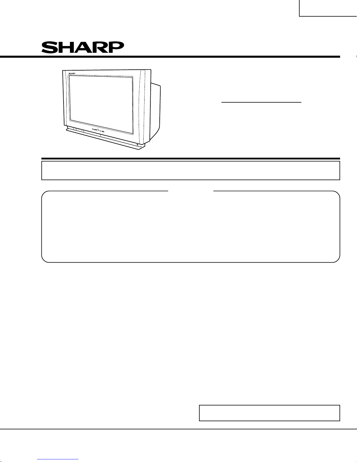
G1550CE
TWIN CH
VIEW
MODE TWIN
PICTURE
VCR
POWER
MTS/SAP
L - TWIN ZOOM - R
SWAP FREEZE
BCD
CATV
HD-Ready TV
VCR CH
FAVORITES
VCR
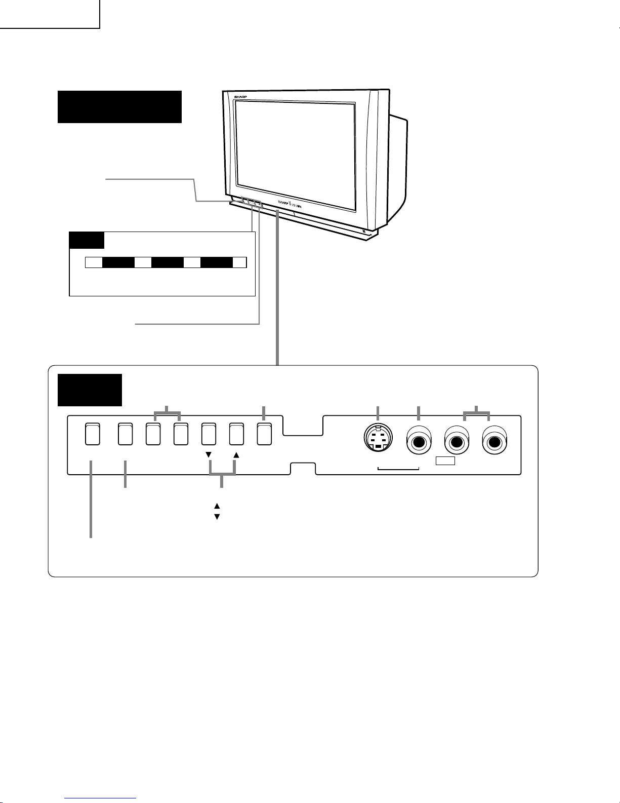
INPUT
Press →Switches to external video
INPUT 1 mode.
Press again →Switches to external video
INPUT 2 mode.
Press 3 times →Switches to external video
INPUT 3 mode.
Press 4 times →Switches to external video
INPUT 4 mode.
Press 5 times →Switches to external video
INPUT 5 mode.
Press 6 times →Switches back to the
original TV mode.
POWER
Press →On.
Press again →Off. (Stand-by)
FAVORITES buttons
•
Used to select any of four preset channels.
Cursor buttons
Used to move cursor on menu screen.
ENTER button
CHANNEL UP/DOWN
(+) Selects next higher channel.
(–) Selects next lower channel.
VOLUME UP/DOWN
(+) Increases sound.
(–) Decreases sound.
MENU
Press →Accesses MAIN MENU.
Press again →Exits MAIN MENU.
AV MODE
MUTE
Press →Mutes sound.
Press again →Restores sound.
•
CLOSED CAPTION appears when sound is muted.
DIRECT ACCESS
Accesses any channel by the keypad.
button: Sharp DTV Decoder only
ENT.
Used in some instances where a VCR or
Cable Converter Box requires an “enter”
command after selecting channels, when
using the DIRECT ACCESS button.
DISPLAY
Press →Displays receiving channel for 4
seconds.
Press again →Displays remaining time of
SLEEP TIMER and VIEW
TIMER for 4 seconds.
FLASHBACK
Returns to previously viewed channel.
VIEW MODE
Select view size.
CC (Closed Caption)
Displays captions during
closed-caption broadcasts.
MTS/SAP
MTS/SAP select
VCR CONTROL
DDFC
Used to select High-quality image.
LIGHT
When this button is pressed , some buttons on the
remote control unit will light. The lighting will turn off if no
operations are performed within about six seconds. This
button is used for performing operations in dark places.
ANT-A/B button
Press to switch between ANTENNA-A and
ANTENNA-B when you wish to watch TV.
Remote control mode select buttons
Use to switch the remote control unit modes.
•
This remote control can be used to operate the TV,
a DTV/STB Decoder and a Cable TV converter.
•
By selecting one of the three mode select buttons,
this remote control can be used to adjust common
functions, such as channel selection, for that device.
INFRARED TRANSMITTER WINDOW
POP FUNCTION
With the VIDEO inputs, you can watch two pictures at
the same time.
"-TWIN CH-': Used to switch the channel for the
sub-picture of the TWIN PICTURE
screen.
TWIN PICTURE: Press to turn the TWIN PICTURE
screen function on and off.
SEARCH: Press to select the SEARCH
screen mode.
SELECT: Selects the screen for switching
the channel or input source.
FREEZE: When this button is pressed with
the regular screen, will change to the
TWIN PICTURE screen and the
picture at the time the button was
pressed will become the sub-picture,
displayed as a frozen image.
L-TWIN ZOOM: The left screen is enlarged with the
TWIN PICTURE function.
TWIN ZOOM-R: The right screen is enlarged with the
TWIN PICTURE function.
SWAP: The left and right screens are
interchanged with the TWIN
PICTURE function.
Note
For use of this remote control with an analog TV.
Note
•The above shaded buttons on the Remote Control glow in the dark. To use the glow-in-the-dark display on the
remote control, place it under a fluorescent light or other lighting.
•The phosphorescent material contains no radioactive or toxic material, so it is safe to use.
•The degree of illumination will vary depending on the strength of lighting used.
•The degree of illumination will decrease with time and depending on the temperature.
•The time needed to charge the phosphorescent display will vary depending on the surrounding lighting.