5
5-1 5-2
25WF30
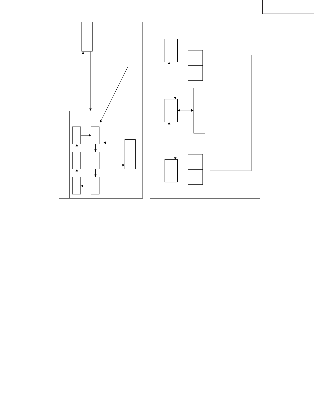
After short JA373 & JA374, and turn on the main power switch, read data from EEPROMAddress
00H ~ 03H, and compare to the list below, if different, initialize the EEPROM.
Address Data Address Data
00H 23H 02H 18H
01H 23H 03H A3H
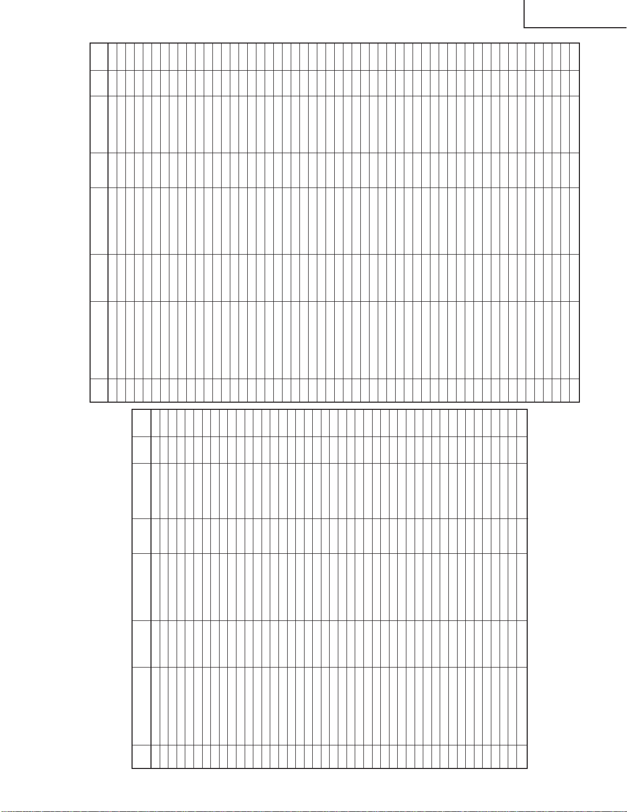
1. SERVICE MODE 1
No. EEPROM SETTING
DATA LENGTH
OSD IC DATA SETTING
INITIAL
EEPROM
DATA
0 MICOM INFO. DISPLAY SERVICE MODE
1 CUT OFF REFER # CUTOFF BKGD
2 CUT OFF (DVD) REFER # CUTOFFBKGD (DVD)
3 V-SIZE 0 ~ 63 V-SIZE 50 1 CHIP V-SIZE 30
4 V-LINEARITY (50Hz) #2 0 ~ 15 V S-LINE 50 1 CHIP V-LINEARITY 10
5
VS-CORRECTION (50Hz) #2
0 ~ 15 V S-CORR 50 1 CHIP
V S-CORRECTION
8
6 V-POSITION #2 0 ~ 7 V-CENT 50 1 CHIP V-PHASE 5
7 H-POSITION #2 0 ~ 31 H-CENT 50 1 CHIP H-PHASE 11
8 H-SIZE (50Hz) #2 0 ~ 63 H-SIZE 50 1 CHIP H-SIZE 32
9
E/W-PARABOLA (50Hz) #2
0 ~ 63 E/W PAR 50 1 CHIP E/W PARABORA 39
10 E/W CORNER (50Hz) #2 0 ~ 15 E/W COR 50 1 CHIP E/W CORNER 6
11 TRAPEZIUM (50Hz) #2 0 ~ 31 TRAPE 50 1 CHIP TRAPEZIUM 17
12 SECAM R-Y #3 0 ~ 15 SCM R-Y 1 CHIP SR-Y 8
13 SECAM B-Y #3 0 ~ 15 SCM B-Y 1 CHIP SB-Y 8
14 BRIGHT 0 ~ 127 SUB BRI 1 CHIP BRIGHTNESS 80
15 BRIGHT (DVD) 0 ~ 127 SUB BRI DVD 1 CHIP BRIGHTNESS 80
16 SUB CONT 0 ~ 15 SUB CONT 1 CHIP SUB CONT 3
17 SUB CONT (DVD) 0 ~ 15 SUB CONT DVD 1 CHIP SUB CONT 3
18 TINT 0 ~ 127 SUB TINT 1 CHIP TINT 64
19 TINT (DVD) 0 ~ 127 SUB TINT DVD 1 CHIP TINT 16
20 V-SIZE 0 ~ 63 V-SIZE 60 1 CHIP V-SIZE 39
21 V-LINEARITY 0 ~ 15 V-LINE 60 1 CHIP V-LINEARITY 10
22 VS-CORRECTION (60Hz) 0 ~ 15 V S-CORR 60 1 CHIP
V S-CORRECTION
9
23 V-POSITION (60Hz) 0 ~ 7 V-CENT 60 1 CHIP V-PHASE 2
24 H-POSITION (60Hz) 0 ~ 31 H-CENT 60 1 CHIP H-PHASE 14
25 H-SIZE (60Hz) 0 ~ 63 H-SIZE 60 1 CHIP H-SIZE 34
26 E/W PARABOLA (60Hz) 0 ~ 63 E/W PAR 60 1 CHIP E/W PARABORA 19
27 E/W CORNER (60Hz) 0 ~ 15 E/W COT 60 1 CHIP E/W CORNER 4
28 TRAPEZIUM (60Hz) 0 ~ 31 TRAPE 60 1 CHIP TRAPEZIUM 6
29 COLOUR 0 ~ 127 SUB COL 1 CHIP COLOUR 60
30 COLOUR (DVD) 0 ~ 127 SUB COL DVD 1 CHIP COLOUR 60 45
31 V-ENT 0 ~ 7 V-ENT 1 CHIP V-ENT 6
32 H-ENT 0 ~ 7 H-ENT 1 CHIP H-ENT 4
33 RF AGC 0 ~ 63 RF AGC 1 CHIP RF AGC 46
34 SECAM BELL 0 ~ 1 SCM BELL 1 CHIP S BELL 0
35 SPRIT/INTER 0 ~ 1 S/I 1 CHIP SPRIT/INTER 0
36 RF SUB SOUND 0 ~ 127 RF S-SOUND 1 CHIP RF SUB SOUND 96
37 SUB VOLUME 0 ~ 63 SUB VOL SOR/SPA VOLUME 45
38
H. PHONE SUB VOL.ADJ.
0 ~ 63 HP SUB VOL SOR/SPA VOLUME 63
39 COLOUR TEMP. 0 ~ 1 WT OPTION 1
40 PIF VCO #4 PIFVCO -
41 LNA ON/OFF LNA OPTION OFF
42 SIF574 ON/OFF SIF574 1 CHIP SIF574 OFF ON
43 AFC AFC OFF
#1 Whiles selecting SERVICE MODE 1, MICOM Version Information, SOFTWARE Version Informa-
tion, check some iformation will be displayed.
#2 60 Hz Adjustment Value is programmed from ± 50 HzAdjustment value (± will be informed later)
#3 While adjusting SECAM R-Y, SECAM B-Y and S BLACK of 1 chip is set to 1.
#4 While choosing PIFVCO MODE and RF AGC set to "0 0" and PIFVCO is set to "1".
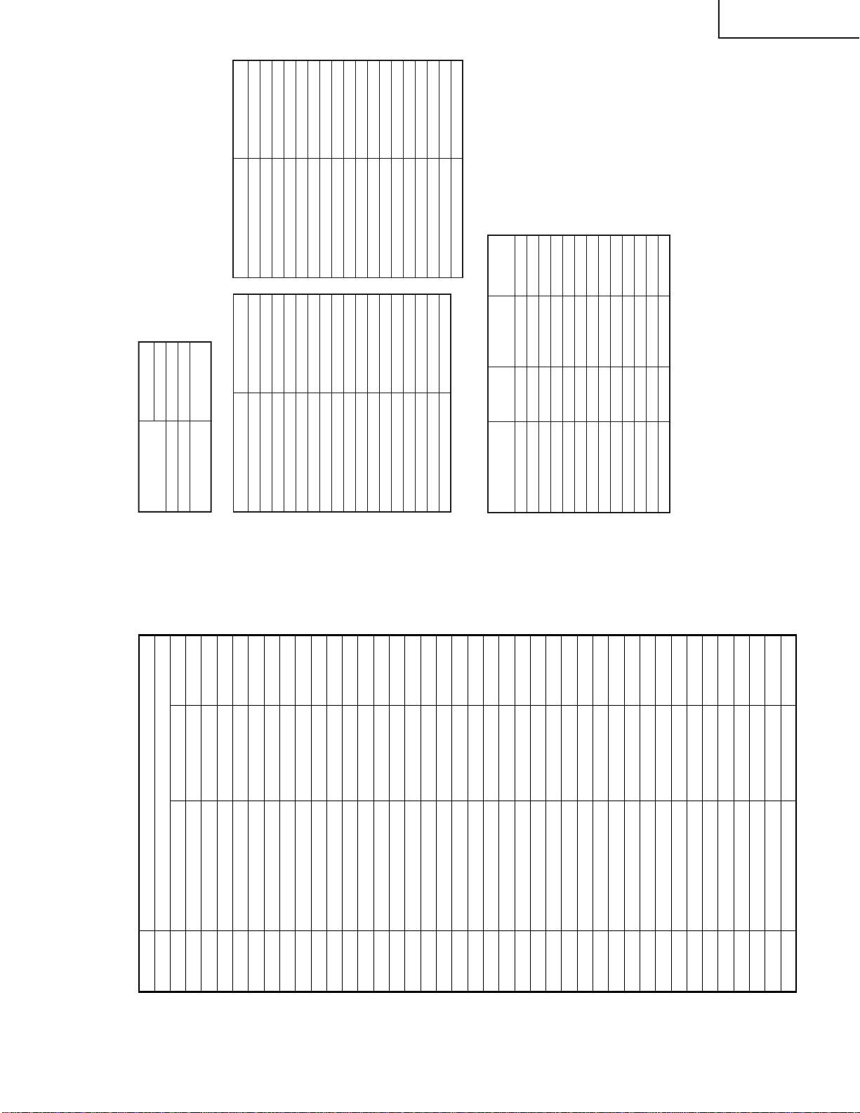
2. SERVICE MODE 2
NO. EEPROM ITEM
DATA LENGTH
OSD IC DATA SETTING
INITIAL EEPROM
DATA
1 WPS 0 ~ 1 WPS 1 CHIP WPS 1
2 SUB CONTRAST 0 ~ 127 S CONT 1 CHIP CONTRAST 127
3 NTSC PHASE (NT) 0 ~ 3 N-PNT 1 CHIP NTSC PHASE 0
4 NTSC PHASE (PAL/SEC.) 0 ~ 3 N-P PS 1 CHIP NTSC PHASE 0
5 NTSC PHASE (DVD) 0 ~ 3 N-PD 1 CHIP NTSC PHASE 3
6 SUB SHARPNESS (TV) 0 ~ 63 S SHARP T 1 CHIP SHARPNESS 10 12
7 SUB SHARPNESS (AV) 0 ~ 63 S SHARP A 1 CHIP SHARPNESS 10 20
8 SUB SHARPNESS (DVD) 0 ~ 63 S SHARP D 1 CHIP SHARPNESS 10 20
9 RGB MUTE 0 ~ 1 RGB MUTE 1 CHIP RGB MUTE OFF
10 RGB CONTRAST 0 ~ 63 RGB CONT 1 CHIP RGB CONTRAST 32
11 Y-DL (NTSC-M) 0 ~ 3 YNM 1 CHIP Y-DL 1
12 Y-DL (PAL-B/G) 0 ~ 3 YPB 1 CHIP Y-DL 1
13 Y-DL (PAL-I) 0 ~ 3 YPI 1 CHIP Y-DL 3
14 Y-DL (PAL-D/K) 0 ~ 3 YPD 1 CHIP Y-DL 3
15 Y-DL (SECAM-B/G) 0 ~ 3 YSB 1 CHIP Y-DL 0
16 Y-DL (SECAM-D/K) 0 ~ 3 YSD 1 CHIP Y-DL 3
17 Y-DL (B/W) 0 ~ 3 YBW 1 CHIP Y-DL 0
18 Y-DL (NTSC-AV) 0 ~ 3 YNA 1 CHIP Y-DL 0
19 Y-DL (PAL-AV) 0 ~ 3 YPA 1 CHIP Y-DL 0
20 Y-DL (SECAM-AV) 0 ~ 3 YSA 1 CHIP Y-DL 0
21 Y-DL (B/W-AV) 0 ~ 3 YBA 1 CHIP Y-DL 0
22 SUB COLOUR 0 ~ 31 SUB COL 1 CHIP SUB-COLOUR 16
23 VSM GAIN AVM1 0 ~ 7 V-GAIN 1 1 CHIP VSM GAIN 3
24 VSM GAIN AVM2 0 ~ 7 V-GAIN 2 1 CHIP VSM GAIN 5
25 VSM GAIN AVM3 0 ~ 7 V-GAIN 3 1 CHIP VSM GAIN 7
26 BASE BAND TINT 0 ~ 31 B-B TINT 1 CHIP BASE BAND TINT
27 SECAM GP-PHASE 0 ~ 3 S G-PHASE 1 CHIP S SP-PHASE 1
28 SECAM ID-SENS 0 ~ 1 S ID-SENS 1 CHIP S ID-SENS 0
29 SECAM ID-MODE 0 ~ 1 S ID-MODE 1 CHIP S ID-MODE 0
30 PIF FREQ 0 ~ 7 P FREQ 1 CHIP PIF FREQ 3
31 P/N-ID 0 ~ 1 PN ID 1 CHIP P/N-ID 0
32 YS/YM MODE 0 ~ 1 YSM MODE 1 CHIP YSM MODE 1
33 RGB ABCL 0 ~ 1 RGB ABCL 1 CHIP RGB ABCL 1
34 DC RESTORATION 0 ~ 3 DC REST 1 CHIP
DC RESTORATION
3
35 BLACK STRETCH 0 ~ 3 B ST 1 CHIP BLACK STRETCH 1
36 ABL START POINT 0 ~ 3 ABL ST 1 CHIP
ABL START POINT
3
37 ABL GAIN 0 ~ 3 ABL GA 1 CHIP ABL GAIN 2
38 AKB MODE 0 ~ 63 AKB MODE 1 CHIP AKB MODE 0
39 COLOUR 0 ~ 1 COL G 1 CHIP COLOUR 1
40 V AGC 0 ~ 1 V AGC 1 CHIP VAGC 0
41 V RAMP REF 0 ~ 1 V RAMP 1 CHIP V RAMP 1
42 VSM PHASE 0 ~ 1 VSM PHASE 1 CHIP VSM PHASE 0
43 BASS LEVEL ON 0 ~ 3 BA LV SUR/SPA BASS LEVEL 0
44 BASS OFF AVM1 SP1 0 ~ 4 #1 BA OFF 1 SP1 SUR/SPA BASS SW, LEVEL 4
45 BASS OFF AVM2 SP1 0 ~ 4 #1 BA OFF 2 SP1 SUR/SPA BASS SW, LEVEL 4
46 BASS OFF AVM3 SP1 0 ~ 4 #1 BA OFF 3 SP1 SUR/SPA BASS SW, LEVEL 4
47 BASS OFF AVM1 SP2 0 ~ 4 #1 BA OFF 1 SP2 SUR/SPA BASS SW, LEVEL 4
48 BASS OFF AVM2 SP2 0 ~ 4 #1 BA OFF 2 SP2 SUR/SPA BASS SW, LEVEL 4
49 BASS OFF AVM3 SP2 0 ~ 4 #1 BA OFF 3 SP2 SUR/SPA BASS SW, LEVEL 4
50 BASS OFF AVM1 SP3 0 ~ 4 #1 BA OFF 1 SP3 SUR/SPA BASS SW, LEVEL 4
51 BASS OFF AVM2 SP3 0 ~ 4 #1 BA OFF 2 SP3 SUR/SPA BASS SW, LEVEL 4
52 BASS OFF AVM3 SP3 0 ~ 4 #1 BA OFF 3 SP3 SUR/SPA BASS SW, LEVEL 4
53 BASS OFF AVM1 SP4 0 ~ 4 #1 BA OFF 1 SP4 SUR/SPA BASS SW, LEVEL 4
54 BASS OFF AVM2 SP4 0 ~ 4 #1 BA OFF 2 SP4 SUR/SPA BASS SW, LEVEL 4