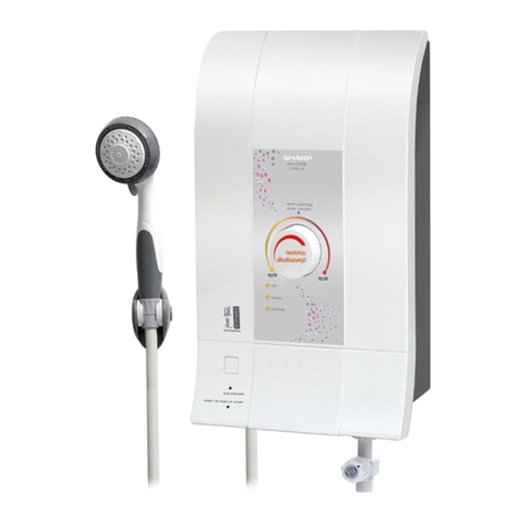
Sharp WH-A55 User manual

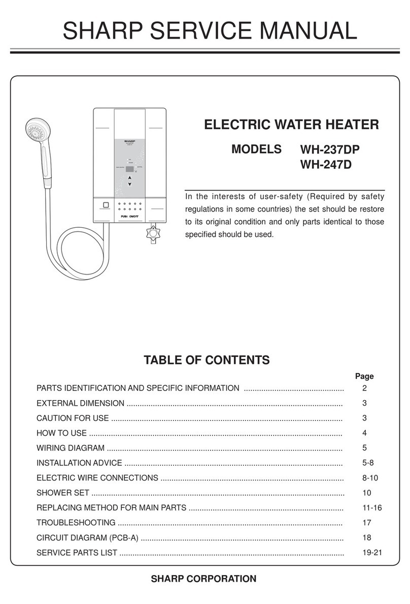
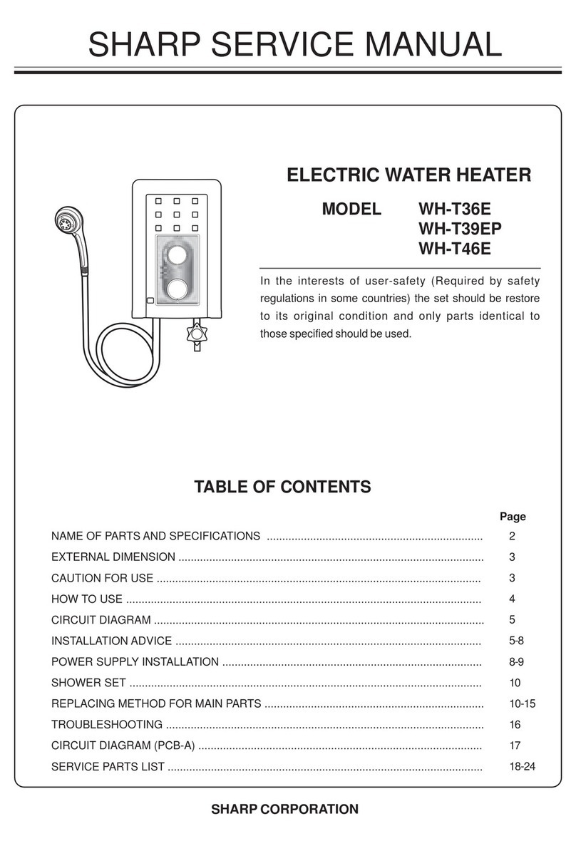
SHARP SERVICE MANUAL
ELECTRIC WATER HEATER
MODELS WH-A55
WH-A57
WH-A58P
WH-HOT HOT
SHARP CORPORATION
TABLE OF CONTENTS
PARTS IDENTIFICATION AND SPECIFIC INFORMATION ......................................................
EXTERNAL DIMENSION .........................................................................................................
CAUTIONS FOR USE ..............................................................................................................
HOW TO USE ...........................................................................................................................
WIRING DIAGRAM ...................................................................................................................
INSTALLATION ADVICE ..........................................................................................................
SHOWER SET ...........................................................................................................................
REPLACING METHOD FOR MAIN PARTS ..............................................................................
TROUBLESHOOTING ..............................................................................................................
CIRCUIT DIAGRAM (PCB CONTROL ASS’Y) .........................................................................
SERVICE PARTS LIST ...............................................................................................................
Page
2
3
3
4
5
5-9
9
10-14
15
16
17-21
In the interests of user-safety (Required by safety
regulations in some countries) the set should be restore
to its original condition and only parts identical to those
specied should be used.

Single point
Approximately 50oC (Maximum)
0.02 MPa (0.21 Bar)
0.34 MPa (3.39 Bar)
218 x 339 x 98
2
PARTS IDENTIFICATION
SPECIFIC INFORMATION
Model
Rated voltage (V)
Rated frequency (Hz)
Power consumption (W)
Water supply system
Water temperature control
Minimum pressure
Maximum pressure
Product dimension (W x H x D) (mm.)
IP number
Weight (kg)
WH-A55 WH-A57 WH-A58P WH-HOT HOT
Note : Temperature of inlet water is approximately 25oC and ow rate is 2.3 liters/min.
: 1 MPa (Megapascal) = 10.2 kg/cm2 (Kilograms/Square centimeter).
Main water valve
Shower hose
Breaker angle support
ELB checker button
Shower stand
Shower head
Main breaker
Temperature knob
Body
Power cord and ground wire
Heater lamp
Water volume knob
(WH-A57, WH-A58P only)
220
50
1.8
3,500 4,500
1.9 1.85
IPX4

3
EXTERNAL DIMENSION
Front
(Unit in mm.)
218
339
Fig. 1
CAUTIONS FOR USE
1. Always turn off the main breaker before making any repairs to your electric water heater.
2. Do not install water valve or faucet at hot water outlet. (Fig. 2)
3. Do not spray water on this electric water heater or put wet towels on it. (Fig. 3)
4. Do not cover the shower head with hands or towels or fold the shower hose. (Fig. 4)
5. If you see the light within your house is ashing from time to time while showering due to irregularity of
electricity, the water temperature may change and this is not unusual.
6. In case that using other faucet at the same as using electric water heater (common main water pipe), the
water pressure and ow may be reduced and it may cause higher water temperature. This is not unusual.
You should adjust water volume or reset water temperature in appropriate way.
7. In the event of thunder and lightning storm, turn off the main breaker to prevent the damage that may
occur on this appliance.
8. Close supervision is necessary in order to check on the water temperature when used by children,
elderly, patients and disabled person.
9. In case of tap water outage while using, turn the temperature knob to “OFF” and the water volume knob
to turn off the water (to avoid water automatically owing when you are not in the bathroom after tap
water ow resumes).
10. While we using a product if that is stop working immediately as we do not know the cause, please inform
the SHARP service center for proceed to repair.
Side
98
Fig. 4
Fig. 2
Water outlet
Water inlet
Water valve
Fig. 3

1. Using the temperature knob.
Turn the temperature knob to adjust water temperature as desired.
OFF : Turn the heater off and water will ow at the normal temperature.
HIGH : The water temperature is 50oC degree approximate.
2. Using the water volume knob. (WH-A57, WH-A58P only)
Turn the knob counterclockwise will increase the volume and decrease the temperature simultaneously.
Turn the knob clockwise will decrease the volume and increase the temperature simultaneously.
BEFORE USE
The installation work is to be done by the Authorized “SHARP” Dealer.
The electric home shower unit must earthed.
Special skill is required. Never try to repair the unit by yourself.
1. Open the main water valve from the home main water pipe.
2. Open the main breaker switch.
3. Push the breaker angle support up to activate the heater electrical system.
4. Turn the water volume knob as desired (see the water volume knob detail in water temperature adjustment).
5. Turn the temperature knob from “OFF” clockwise to adjust the desired temperature. The heater lamp (red)
will be illuminated and the warm water will ow from the shower head (see the detail in water temperature
adjustment).
6. After use, turn the temperature knob to “OFF” and turn the water volume knob to stop the ow.
7. Turn off the main breaker switch.
Note : In case of electricity or tap water outage while using, always turn the temperature knob to “OFF” and
the water volume knob clockwise to shut the heater before leaving the bathroom.
4
ADJUSTMENT WATER TEMPERATURE
HOW TO USE
Temperature knob
Heater lamp
ELB checker button

5
WIRING DIAGRAM
INSTALLATION ADVICE
1. Before installation.
1.1 Please check water pressure before operating this unit.
Minimum water pressure : 0.02 MPa (0.21 Bar).
Maximum water pressure : 0.34 MPa (3.39 Bar).
Please follow the picture below to check water pressure. Water shall overow at the end of the tube
within 2.3 meters above the faucet.
2. Installation the unit.
2.1 Preparing installation area.
The unit must be mounted to the wall in a vertical position only. (See in the picture)
Leave this unit away from the wall for both sides more than 200 millimeters.
The minimum height of 1.5 meters to the lower edge of the unit must be observed.
About 2.3 meters
1.5 meters
Fig. 5
Fig. 6 Fig. 7

6
2.4 Assemble the cover with the heater.
Make sure that the temperature knob at “OFF” position.
Push unit cover on to body unit until they are locked.
Tighten screws to attach the cover with the heater and place the temperature knob to the same place.
2.2 Removing the unit cover.
Turn the temperature knob to “OFF” position and remove the screw underneath the unit.
Open the cover by lifting from the bottom.
2.3 Mounting the unit to the wall.
Drill two 6 millimeters holes in the wall with approximately 25 millimeters in depth.
Install wall anchors into the holes.
Screw the top wall anchors, leave screw length around 8-10 millimeters and hang the unit on the screw
and hang the unit on the screw then marked the position in order to drill another 2 holes at the bottom,
drill the holes and install the rest of wall anchors then fasten all of 4 screws.
Fig. 10
Fig. 11
Fig. 9
25 mm.
6 mm.
Fig. 8
Screw
Push on at the top
Temperature knob
Push off the body
Screw

7
Fig. 13
2.5 The shower assembly.
The joint and shower hose counterclockwise with the shower head.
2.6 Installation the shower stand.
Ensure that the shower stand located in the level that the top part of the shower head is not higher
than the top part of the unit when hanging the shower head. (See in the picture)
The angle of shower head holder can adjust into 2 levels.
Fig. 12
Notication in connecting the shower hose.
Shower head
Joint
Shower hose
Connect to the unit.
Connect to the shower head.
3. Piping installation.
3.1 Connection point between the unit and the water volume knob and twist the shower hose by hands until
tight. Do not use any tools during assembly because it may cause the damage to plastic components.
3.2 Tighten the connection into the thread located at the bottom of the water volume knob, Force gauge do
not exceed 40 kgf.cm.
3.3 Connect water inlet pipe and water outlet pipe as shown in the picture.
Fig. 14
Water inlet
Filter
O-ring
Main water valve
Water volume knob
Use pipe at least 15 cm. in length
Shower head
O-ring lter
Shower hose

8
4.2 Electric wire connection to the unit can be done by 2 methods. (as illustrated). Drill a small hole at the rubber
to insert the wire on side or at the rear of the unit.
Peel the wire and connect to the ELB checker by connecting the high voltage cable to the terminal “L”
and connect neutrons wire into the terminal “N”. Use screwdriver to tighten the wires. (Force gauge
approximately 12 kgf.cm). If the wires are connected into the wrong terminal, the unit will not work
properly. It may result in damage to the circuit or may cause danger to the user.
4. Electric wire connections.
4.1 Before connection the wires, please make sure the main breaker is off to cut off power.
Use dual insulated wire with at least 4 square millimeters cross-section.
Connect electric wire to the unit from the main breaker board through the main breaker which is located
the bathroom. Wire connection must be permanent.
Main breaker
Bathroom
Earth ground
Ground wire Ground wire
Connect the wire at rear of the unit.
Fig. 16
Fig. 17
Connect the wire on side of the unit.
(Force gauge 12 kgf.cm)
Fig. 15
Ground wire
50 mm.20 mm.
12 mm. 30 mm.

9
SHOWER SET
Shower heads allow users to adjust into 3 types by simply twisting the shower head cover as show the picture.
4.3 The ground wire must be connected to grounding point on the unit.
Ground rod installation, select the area where moisture stored in the soil and away from ood area with no
sand or limestone.
The diameter of ground rod is not less than 16 millimeters and the length is not less than
240 centimeters.
Embed the ground rod at least 30 centimeters in depth from ground surface.
Grounding process.
4.4 Ground resistance must be less than 5 ohm.
4.5 After grounding process is completed, if ground resistance is higher than 5 ohm, additional ground
rod must be embedded. Leave the additional one away from the previous ground rod at least equal to
the length of ground rod. Connect them together in parallel.
Tools for embedded
At least 30 cm.
Ground surface
Ground rod
Fig. 18
JET TYPE
SPRAY TYPE
COMFORT TYPE
Match the sign with
your designed type.
LEFT RIGHT
Fig. 19

10
1. Remove the screw underneath the unit.
2. Open the cover by lifting from the bottom.
3. Now the body is free.
REMOVE OF BODY
REPLACING METHOD FOR MAIN PARTS
1. Turn out the joint body between the body with the shower hose manually. Never use other tools to
avoid breaking plastic parts.
REMOVE OF SHOWER HOSE
Fig. 20
Body
Shower hose
Body
Screw
Back cover
Fig. 21

11
REMOVE OF TRIAC
1. Remove the body in accordance with “REMOVE OF BODY”.
2. Disconnect 3 lead wires from the triac.
3. Remove 2 screws holding the triac to the heater tank ass’y.
4. Now the triac is free.
1. Remove the body in accordance with “REMOVE OF BODY”.
2. Disconnect reed SW. lead wires from the PCB control ass’y.
3. Remove 2 screws holding the reed SW. from the body valve.
4. Now the reed SW. is free.
Note : Tighten the mounting screws of the reed switch at the specied torque ; 3-4 kgf.cm.
REMOVE OF REED SWITCH
Fig. 23
Reed SW. lead wire
Fig. 22
Breaker lead wire
Heater tank
Screw
Triac
White lead wire
Triac lead wire
Brown lead wire
Body valve
Screw
Reed SW.

Fig. 24
12
1. Remove the body in accordance with “REMOVE OF BODY”.
2. Remove the reed SW. in accordance with “REMOVE OF REED SWITCH”.
3. Detach 2 clamping springs holding the body valve ass’y and the water outlet to the heater tank ass’y.
4. Remove 2 screws holding the body valve ass’y.
5. Remove 2 screws holding the water outlet.
6. Now the body valve ass’y and the water outlet are free.
REMOVE OF BODY VALVE ASS’Y AND WATER OUTLET
1. Remove the triac in accordance with “REMOVE OF TRIAC”.
2. Remove the body valve ass’y and the water outlet in accordance with “REMOVE OF BODY VALVE ASS’Y
and WATER OUTLET”.
3. Remove the screw to L-Wire Earth from heater tank ass’y.
4. Remove the screw holding cable tie from the heater tank support.
5. Remove 2 screws holding triac lead wire (brown) and thermostat lead wire (black) to the heater tank ass’y.
6. Remove 2 screws holding the thermostat to the heater tank ass’y.
7. Now the heater tank ass’y is free.
REMOVE OF HEATER TANK ASS’Y
Back cover
Thermostat lead
wire black
Screw
Screw
L-wire earth
Brown lead wire
Triac lead wire brown
Black lead wire
Breaker lead
wire black
Screw
Screw
Cable tie
Heater tank support
Heater tank ass’y Thermostat
Back cover
Heater tank
Water outlet
Screw
Clamping spring
Body valve ass’y
Screw
Fig. 25

13
1. Remove the body in accordance with “REMOVE OF BODY”.
2. Remove the nut holding the volume SW. to the tting plate.
3. Remove 2 screws holding the tting plate to the back cover.
4. Cut off the volume SW. lead wire at PCB control ass’y.
5. Now the volume SW. ass’y is free.
REMOVE OF VOLUME SW. ASS’Y
1. Remove the body in accordance with “REMOVE OF BODY”.
2. Disconnect reed SW. lead wire from PCB control ass’y.
3. Remove the screw holding the PCB control ass’y.
4. Cut off the volume SW. lead wire at the PCB control ass’y.
5. Disconnect the white lead wire from the triac and the
breaker.
6. Disconnect lead wire red from the triac.
7. Remove 2 screws holding lead wire brown
and lead wire black from heater tank.
8. Now the PCB control ass’y is fee.
REMOVE OF PCB CONTROL ASS’Y
Volume SW.
Fitting plate
Screw
Nut
Back cover
Fig. 26
Fig. 27
Back cover
Insulation sheet
White lead wire
PCB control ass’y
Brown lead wire
Black lead wire
Screw
Volume SW. lead wire

14
1. Remove the body in accordance with “REMOVE OF BODY”.
2. Remove split pin holding the breaker angle support to the breaker.
3. Remove 2 screws holding 2 breaker lead wires to the breaker.
4. Remove 2 screws holding the breaker to the back cover.
5. Now the breaker is free.
REMOVE OF BREAKER
Note : For disassembly
Cut off the lead wire from PCB control ass’y.
Volume SW.
Blue lead wire
Back cover
Screw
Split pin
Breaker angle support
Breaker
Breaker lead wire
White lead wire
Orange lead wire
Fig. 29
Fig. 28
Orange lead wire

15
1. Remove the body in accordance with “REMOVE OF BODY”.
2. Remove the screw holding the neon lamp ass’y to the back cover.
3. Cut neon lamp lead wire to PCB control ass’y.
4. Now the neon lamp ass’y is free.
REMOVE OF NEON LAMP ASS’Y
TROUBLESHOOTING
Water is not hot. Heater tank ass’y shock.
Low pressure water.
Thermostat trip. (Cut off)
Volume SW. is defected.
Reed SW. is defected.
PCB control ass’y is defected.
Replace heater tank ass’y.
Check water pressure from main
water valve.
Reset thermostat.
Check or replace the volume SW.
Replace reed SW.
Replace PCB control ass’y.
Water temperature can not
be set.
PCB control ass’y is defected. Replace PCB control ass’y.
O-ring is clogged.
Shower ass’y is clogged.
Main water valve open too low.
Main water valve is closed.
Water volume is closed.
Problem Possible cause Corrective action
Volume SW. is defected. Check or replace volume SW.
Water ow out from shower
ass’y is too low.
Check and clean O-ring.
Check and clean shower course.
Open the main water valve to increase.
Open the main water valve.
Open the water volume.
Water is not ow out from
shower ass’y.
Fig. 30
Screw
Black lead wire
Neon lamp ass’y

16
CIRCUIT DIAGRAM (PCB CONTROL ASS’Y)
T1
T2
G
TR1
TG25C60(3500W)
VR1
350K
S1
VOLUME SW
85'C
S2
FLOW_SW
POWER & CONTROL SIDE (PCB-1)
white
white
orange
blue
red
1
2
3
CN3_1
A
C
White
NEON LAMP
1
2
3
4
CN1_1
1
2
3
CN2_1
1
2
CN4_1
R3
15K 1/2W small
R2
3.3K
R4
47
C2
39nF 400V
DIAC1
DB3
C1
39 nF 400V
R1
100k
1
2
3
CN3
D1
1N4007
R6
47K
R7 100k 1/2w(s)
R5
1K
ZD1
BZX55C12
Q1
KSP44
1
2
3
4
CN1
1
2
3
CN2
1
2
CN4
R9 100k 1/2W(s)
R8 100k 1/2W(s)
C3
33uF/50v
D2
B6M
TG35C60(4500W)
V in
220V
ELB
black
THERMOSTAT 1 MAIN HEATER
black brown
black
L
N

SERVICE PARTS LIST
Model WH-A55
17
REF. NO
PARTS CODE
DESCRIPTION Q’TY PRICE
(FEC)
PRINTING & PACKAGING MATERIAL
1-1 71T107 INSTRUCTION BOOK 1
1-2 71T100 SET PACKING CASE 1
1-3 71T101 CARTON BOX 1
1-4 71T102 NAME PLATE 1
1-5 71B1051 LOWER PAD 1
1-6 71B1061 UPPER PAD 1
MECHANICAL PARTS
2-1 71T200ASY BODY ASS’Y 1
2-2 7N7122 TEMP. CONTROL KNOB 1
2-3 7N706 SPLIT PIN 1
2-4 7N6182 BREAKER ANGLE SUPPORT 1
2-5 7K102 WATER OUTLET 1
2-6 7D9241 PLUG 2
2-7 71B201 BACK COVER 1
2-8 7D601 AC LINE CLAMP 1
2-9 7N608 RUBBER CAP 1
2-10 7K727 FITTING PLATE 1
2-11 7A220 CLAMPING SPRING 2
2-12 71T216ASY BODY VALVE ASS’Y 1
2-13 71T215 INSULATION SHEET 1
2-14 71B401SET HEATER TANK SET 1
2-15 7K1361 HEATER TANK SUPPORT 1
2-16 7K137 CABLE TIES 1
2-17 71A2041ASY SHOWER ASS’Y 1
2-18 7A901ASY SHOWER HOSE ASS’Y 1
2-19 7A910 SHOWER STAND 1
2-20 7A912 O-RING FIXER 1
ELECTRIC PARTS
3-1 7A605 BREAKER 220V, 30A 1
3-2 71T411 BREAKER LEAD WIRE BLACK 1
3-3 7K442ASY PCB LAMP ASS’Y 1
3-4 7B404AASY VOLUME SWITCH SET 1
3-5 7N405 REED SWITCH ASS’Y 1
3-6 71T412 BREAKER LEAD WIRE WHITE 1
3-7 71T415 PCB CONTROL ASS’Y 1
3-8 71T407 TRIAC LEAD WIRE BROWN 1
3-9 71T416 THERMOSTAT LEAD WIRE BLACK 1
3-10 7N1261 THERMOSTAT 85oC 1
3-11 7A127 TRIAC 600V, 25A 1
3-12 71B413 L-WIRE-EARTH 1

Model WH-A57
18
REF. NO
PARTS CODE
DESCRIPTION Q’TY PRICE
(FEC)
PRINTING & PACKAGING MATERIAL
1-1 71T107 INSTRUCTION BOOK 1
1-2 71U100 SET PACKING CASE 1
1-3 71U101 CARTON BOX 1
1-4 71U102 NAME PLATE 1
1-5 71B1051 LOWER PAD 1
1-6 71B1061 UPPER PAD 1
MECHANICAL PARTS
2-1 71U200ASY BODY ASS’Y 1
2-2 7N7122 TEMP. CONTROL KNOB 1
2-3 7N706 SPLIT PIN 1
2-4 7N6182 BREAKER ANGLE SUPPORT 1
2-5 7K102 WATER OUTLET 1
2-6 7D9241 PLUG 2
2-7 71B201 BACK COVER 1
2-8 7D601 AC LINE CLAMP 1
2-9 7N608 RUBBER CAP 1
2-10 7K727 FITTING PLATE 1
2-11 7A220 CLAMPING SPRING 2
2-12 71T216ASY BODY VALVE ASS’Y 1
2-13 71T215 INSULATION SHEET 1
2-14 71B401SET HEATER TANK SET 1
2-15 7K1361 HEATER TANK SUPPORT 1
2-16 7K137 CABLE TIES 1
2-17 71A2041ASY SHOWER ASS’Y 1
2-18 7A901ASY SHOWER HOSE ASS’Y 1
2-19 7A910 SHOWER STAND 1
2-20 7D924ASY WATER VOLUME ASS’Y 1
2-21 7A912 O-RING FIXER 1
ELECTRIC PARTS
3-1 7A605 BREAKER 220V, 30A 1
3-2 71T411 BREAKER LEAD WIRE BLACK 1
3-3 7K442ASY PCB LAMP ASS’Y 1
3-4 7B404AASY VOLUME SWITCH SET 1
3-5 7N405 REED SWITCH ASS’Y 1
3-6 71T412 BREAKER LEAD WIRE WHITE 1
3-7 71T415 PCB CONTROL ASS’Y 1
3-8 71T407 TRIAC LEAD WIRE BROWN 1
3-9 71T416 THERMOSTAT LEAD WIRE BLACK 1
3-10 7N1261 THERMOSTAT 85oC 1
3-11 7A127 TRIAC 600V, 25A 1
3-12 71B413 L-WIRE-EARTH 1

Model WH-A58P
19
REF. NO
PARTS CODE
DESCRIPTION Q’TY PRICE
(FEC)
PRINTING & PACKAGING MATERIAL
1-1 71T107 INSTRUCTION BOOK 1
1-2 71U120 SET PACKING CASE 1
1-3 71U121 CARTON BOX 1
1-4 71U122 NAME PLATE 1
1-5 71B1051 LOWER PAD 1
1-6 71B1061 UPPER PAD 1
MECHANICAL PARTS
2-1 71U230ASY BODY ASS’Y 1
2-2 7N7123 TEMP. CONTROL KNOB 1
2-3 7N706 SPLIT PIN 1
2-4 7N6182 BREAKER ANGLE SUPPORT 1
2-5 7K102 WATER OUTLET 1
2-6 7D9241 PLUG 2
2-7 71B201 BACK COVER 1
2-8 7D601 AC LINE CLAMP 1
2-9 7N608 RUBBER CAP 1
2-10 7K727 FITTING PLATE 1
2-11 7A220 CLAMPING SPRING 2
2-12 71T216ASY BODY VALVE ASS’Y 1
2-13 71T215 INSULATION SHEET 1
2-14 71B401SET HEATER TANK SET 1
2-15 7K1361 HEATER TANK SUPPORT 1
2-16 7K137 CABLE TIES 1
2-17 71C2041ASY SHOWER ASS’Y 1
2-18 7A9012ASY SHOWER HOSE ASS’Y 1
2-19 7A910 SHOWER STAND 1
2-20 7D924ASY WATER VOLUME ASS’Y 1
2-21 7A912 O-RING FIXER 1
ELECTRIC PARTS
3-1 7A605 BREAKER 220V, 30A 1
3-2 71T411 BREAKER LEAD WIRE BLACK 1
3-3 7K442ASY PCB LAMP ASS’Y 1
3-4 7B404AASY VOLUME SWITCH SET 1
3-5 7N405 REED SWITCH ASS’Y 1
3-6 71T412 BREAKER LEAD WIRE WHITE 1
3-7 71T415 PCB CONTROL ASS’Y 1
3-8 71T407 TRIAC LEAD WIRE BROWN 1
3-9 71T416 THERMOSTAT LEAD WIRE BLACK 1
3-10 7N1261 THERMOSTAT 85oC 1
3-11 7A127 TRIAC 600V, 25A 1
3-12 71B413 L-WIRE-EARTH 1

20
REF. NO
PARTS CODE
DESCRIPTION Q’TY PRICE
(FEC)
PRINTING & PACKAGING MATERIAL
1-1 71X107 INSTRUCTION BOOK 1
1-2 71X100 SET PACKING CASE 1
1-3 71X101 CARTON BOX 1
1-4 71X102 NAME PLATE 1
1-5 71B1051 LOWER PAD 1
1-6 71B1061 UPPER PAD 1
MECHANICAL PARTS
2-1 71X200ASY BODY ASS’Y 1
2-2 7N7122 TEMP. CONTROL KNOB 1
2-3 7N706 SPLIT PIN 1
2-4 7N6182 BREAKER ANGLE SUPPORT 1
2-5 7K102 WATER OUTLET 1
2-6 7D9241 PLUG 2
2-7 71B201 BACK COVER 1
2-8 7D601 AC LINE CLAMP 1
2-9 7N608 RUBBER CAP 1
2-10 7K727 FITTING PLATE 1
2-11 7A220 CLAMPING SPRING 2
2-12 71T216ASY BODY VALVE ASS’Y 1
2-13 71T215 INSULATION SHEET 1
2-14 71X301SET HEATER TANK SET 1
2-15 7K1361 HEATER TANK SUPPORT 1
2-16 7K137 CABLE TIES 1
2-17 71A2041ASY SHOWER ASS’Y 1
2-18 7A901ASY SHOWER HOSE ASS’Y 1
2-19 7A910 SHOWER STAND 1
2-20 7A912 O-RING FIXER 1
ELECTRIC PARTS
3-1 7A605 BREAKER 220V, 30A 1
3-2 71X411 BREAKER LEAD WIRE BLACK 1
3-3 7K442ASY PCB LAMP ASS’Y 1
3-4 7B404AASY VOLUME SWITCH SET 1
3-5 7N405 REED SWITCH ASS’Y 1
3-6 71X412 BREAKER LEAD WIRE WHITE 1
3-7 71T415 PCB CONTROL ASS’Y 1
3-8 71X407 TRIAC LEAD WIRE BROWN 1
3-9 7E6231 THERMOSTAT LEAD WIRE BLACK 1
3-10 7N1261 THERMOSTAT 85oC 1
3-11 7C127 TRIAC 600V, 35A 1
3-12 71X413 L-WIRE-EARTH 1
Model WH- HOT HOT
This manual suits for next models
3
Table of contents
Other Sharp Water Heater manuals
Popular Water Heater manuals by other brands

Lochinvar
Lochinvar EFW 85 Installation, Commissioning, User and Maintenance Instructions

Cordivari
Cordivari Puffer user manual

Aquadon
Aquadon COMPACT Instructions for use

Rheem
Rheem Stellar 850330 Owner's guide and installation instructions

Bradford White
Bradford White Combi2 "CDW2" Series Replacement parts list

LIVINOX
LIVINOX WH T Series Operation manual

Westinghouse
Westinghouse HT382E55 instruction manual

Cipax
Cipax CPX 23020 Installation and user

AquaStar
AquaStar 170 VP Installation and operating instructions

Webasto
Webasto Thermo 90 ST operating instructions

clage
clage Zip DSX 27940 user manual

Santon
Santon Aquarius A7/3 Installation and user instructions