Shelbourne Powerspread Pro 1800-2300 User manual

Issue 6 16/05/2018
1800 –3200 GALLON
OPERATORS MANUAL
ORIGINAL INSTRUCTIONS
MAN-06000
POWERSPREAD PRO


Issue 2
12.04.18
DEALER PRE-DELIVERY / INSTALLATION CHECK AND WARRANTY REGISTRATION –POWERSPREAD
DEALERS PRE-DELIVERY / INSTALLATION CHECK
IMPORTANT ⚠
All items listed below must be checked, and adjusted if necessary. The person conducting the inspection should tick each
item in the space provided, indicating whether or not adjustments were required. In the event of additional work being
needed, details should be given in the additional work / discrepancy box, located at the bottom of this sheet, or on a
separate sheet if required. When the inspection is complete, THIS FORM MUST BE COPIED & RETURNED TO: -
Shelbourne Reynolds within 30 days of delivery to customer, otherwise the invoice date to the dealer will be deemed to
be the start date for the warranty period.
SERIAL NUMBER: ......................................................... MACHINE NUMBER: ..........................................................
MODEL: .........................................................................
PLEASE TICK APPROPRIATE COLUMN FOR EACH ITEM UNDERTAKEN
Dealer Pre Customer Delivery / Installation / Commissioning
Checks OK
Adjusted
Check the PTO shaft length is compatible with the tractor.
Rotate the auger & check there is no unusual scratching or knocking sounds.
Ensure the chain-oiler system (Contractor only) is working correctly, & the chains are pre-greased.
Check chains are tensioned correctly.
Rotate the impeller, check it rotates freely, and is clear of the door and drip tray. Adjust impeller blades
(Dairy) or impeller adjuster studs (Contractor & Pro) as required.
Ensure the hoses are not taught when connected to the tractor.
Check operation of all hydraulic services.
Check hydraulic system for leaks.
Check brake ram operation & adjustment.
Check braking system for oil leaks.
Check tyre pressures.
Check wheel nuts for correct torque setting.
Check operation of handbrake.
Lubricate all grease points.
Check in general that nuts & bolts are tight.
Check paintwork & finish.
Ensure that all safety guards & decals are fitted.
Ensure that an operator‟s manual is supplied with the machine.
Additional Comments:
...........................................................................................................................................................................................
..........................................................................................................................................................................................
Dealer Representative‟s Name: ..............................................................................................
Date: .........................................
Customer Instruction
Actioned
Explain the correct setting & operation of the machine to the customer.
Ensure the machine is correctly attached to the customer‟s tractor.
Ensure the maintenance schedule is explained to the customer.
Ensure the lubrication & grease points are indicated to the customer.
Ensure all safety precautions & warning decals are explained to the customer.
Ensure the warranty policy is explained to the customer.
Ensure that the operators manual is handed to the customer.
Additional Comments:
...........................................................................................................................................................................................
...........................................................................................................................................................................................
Dealer Representative‟s Name: .............................................................................................
Date: .........................................
For specific details please refer to the operator’s manual. Page 1 of 2

Issue 2
12.04.18
DEALER PRE-DELIVERY / INSTALLATION CHECK AND WARRANTY REGISTRATION –POWERSPREAD
Dealer Name: ............................................................................
Address: .........................................................................................................................................................................
.........................................................................................................................................................................
Post / Zip code: .........................................................................
Dealer Salesman Name: ............................................................
Customer Name: ......................................................................
Business Name (if different from above): ............................................................................................................................
Address: .........................................................................................................................................................................
.........................................................................................................................................................................
Post / Zip code: ........................................................................
Email Address: ........................................................................
Tel No. Home / Office: ............................................................... Cell / Mobile:...................................................................
SERIAL NUMBER: ....................................................................MACHINE NUMBER: ......................................................
MODEL: ..................................................................................
Dealer Signature: ...................................................................
Print Name: .......................................................................... Date:.................................................................................
Privacy Notice
Here at Shelbourne Reynolds Engineering Ltd we take your privacy seriously and will only use your personal information to administer your account and
provide the products and services you have requested from us.
We would occasionally like to contact you with details of other products you may be interested in, special offers we provide and details/invitations to
shows, working demonstrations and open days, however this would be no more than once or twice per year. If you consent to us contacting you for this
purpose please tick a box or boxes to say how you would like us to contact you.
Post Email Telephone/SMS
If you prefer not to be contacted, then please tick this box
For further information please refer to our Privacy Policy at www.shelbourne.com
Customers Signature: .............................................................
Print Name:........................................................................... Date:.............................................................
The customer’s signature certifies that the machine was delivered in a satisfactory condition and that adequate instruction was received as to
its correct operation, safety requirements, and maintenance as stated in the operator’s manual, and that the customer has read, understood,
and agrees to the Terms and Conditions of Sale and Warranty (including the disclaimers and limitations) contained in Section 1.5 of the
operator’s manual.
Additional work / discrepancies:
...........................................................................................................................................................................................
...........................................................................................................................................................................................
...........................................................................................................................................................................................
...........................................................................................................................................................................................
...........................................................................................................................................................................................
This page must be faxed or emailed to Shelbourne Reynolds Engineering Ltd.
Fax No: +44 (0)1359 250464 Email: warranty@shelbourne.com
Page 2 of 2

Dear Customer,
Parts manuals are not supplied with this machine, but they can be ordered from your Shelbourne
Reynolds dealer. Alternatively they can be downloaded from the Shelbourne Reynolds website
www.shelbourne.com by clicking on the Parts and Service section of the website, and then
selecting manuals followed by Powerspread Manuals.
The Machine and Parts Manual number for your machine is:
Tick
Machine No.
Manual No.
Machine Description
609905 01
MAN-06100
Powerspread Pro 2400-3200
609905 02
MAN-06100
Powerspread Pro 1800-2300
Powerspread Pro Serial Number
ORDERING SPARE PARTS
To ensure you order the correct part from your SRE dealer please use the following procedure:
ALWAYS QUOTE THE MACHINE AND SERIAL NUMBERS WHEN ORDERING.
Refer to the Parts Manuals front page/s, listing the machine numbers. Select the correct machine
number which is printed in the top left corner of the page (starting with 6099_ _ 01). Your
machines number is listed above or can be found printed on the identification plate located on the
LH side of the front sheet of the tub.
Scan down the page, and select the relevant sub assembly your required part falls within. Sub-
assemblies start from 6090_ _ 01. Note the year or serial number of the machine may determine a
correct sub assembly if more than one is listed.
Continue through the manual and find the relevant sub assembly parts listing. Again the number
will be printed in the top left corner; the sub-assemblies are in numerical order.
Having found the correct parts list, you will find the corresponding drawing by either looking at the
facing page or progressing through the manual to the next drawing.
The drawings indicate the components by item numbers, which you will find, are repeated in the
left-hand side of your parts listing, and therefore referring to the correct part.
Please note that if certain parts cannot be found listed below the sub-assembly numbers, they are
likely to form part of a specific optional kit. These kits will be found in numerical order further
through the manual and start with KIT- _ _ _ _ _.
The tick list located on the following page of this manual will highlight the optional build kits that
were specified with your machine.
PSP

OPTIONAL BUILD KIT LISTING
Tick
Part No.
Description
PTO Shaft Options
KIT-03799a
Wide angle PTO shaft
Towing Eye / Drawbar Options
KIT-03742
Heavy duty UK tow eye
KIT-03764
Heavy duty UK drawbar
Wheel & Tyre Options
KIT-03643
650/65-R30.5 Trelleborg
KIT-03883
560/60-22.5 8 Tandem
KIT-03914
560/60-22.5 10 Tandem
KIT-03892
620/75 R26 Standard
KIT-03915
650/65 R30.5 Trelleborg
Axle Options
KIT-03806
Single hydraulic axle (2400-3200)
KIT-03807
Tandem rear steering hydraulic axle (2400-3200)
KIT-03808
Single hydraulic axle (1800-2300)
KIT-03913
Tandem rear steering hydraulic axle (2400-3200)
Extension / Slurry canopy Options
KIT-03784
Slurry canopy kit (1800-3200)
KIT-03891
Extension side kit (1800-2300)
KIT-03911
Extension side kit (2400-3200)
Anti-bridge kit Options
KIT-03823
Anti-bridging kit (2400-3200)
KIT-03823a
Anti-bridging kit (1800-2300)
KIT-03824
Automatic hydraulic kit (All models)
KIT-03825
Manual hydraulics kit (All models)
KIT-03762
Anti-bridge rear pivot kit (2400-3200)
KIT-03762a
Anti-bridge rear pivot kit (1800-2300)
Other Options
KIT-03745
Straw plate kit (2400-3200)
KIT-03749
Transfers kit
KIT-03770
Blanking plate kit (1800-2300)
KIT-03771
Blanking plate kit (2400-3200)
KIT-03771a
Blanking plate kit (2400-3200)

EC Declaration of conformity for machinery
(Machinery Directive 2006/42/EC, Annex II., sub. A)
Manufacturer: Shelbourne Reynolds Engineering Ltd.
Address: Shepherds Grove Industrial estate,
Stanton,
Bury St Edmunds,
Suffolk.
England.
IP31 2AR
Name and address of the person (established in the European Community/EEA)
authorised to compile the technical file (to the authorities on request):
Name: Mr Neil Smith
Address: As stated above.
Herewith we declare that: DESIGNATION MANURE SPREADER
MAKE: POWERSPREAD PRO
MACHINE No: 609905
SERIAL No: PSP
is in conformity with the relevant provisions of the Machinery Directive (2006/42/EC)
Neil Smith
Director
Place : Stanton, England. Date :

1

2
CONTENTS PAGE
Section 1 INTRODUCTION
1.1 FOREWORD.
1.2 IMPROVEMENTS AND CHANGES.
1.3 SERVICE PARTS.
1.4 MACHINE IDENTIFICATION.
1.5 STANDARD WARRANTY POLICY.
Section 2 SAFETY PROCEDURES
2.1 ACCIDENT PREVENTION.
2.2 SAFETY SIGNS.
2.3 ACCIDENT PREVENTION BEFORE STARTING THE MACHINE.
2.4 ACCIDENT PREVENTION WHEN COUPLING & UNCOUPLING TO THE
TRACTOR.
2.5 ACCIDENT PREVENTION WHEN USING THE HYDRAULIC SYSTEM.
2.6 ACCIDENT PREVENTION WHEN USING THE PTO SHAFT.
2.7 ACCIDENT PREVENTION WHEN OPERATING THE MACHINE.
2.8 ACCIDENT PREVENTION WHEN TAKING ON PUBLIC ROADS.
2.9 ACCIDENT PREVENTION WHEN LEAVING THE MACHINE.
2.10 ACCIDENT PREVENTION WHEN CHANGING A WHEEL.
2.11 ACCIDENT PREVENTION WHEN REMOVING A FOREIGN OBJECT
FROM THE MACHINE.
2.12 ACCIDENT PREVENTION WHEN SERVICING OR WORKING ON THE
MACHINE.
2.13 ACCIDENT PREVENTION WHEN CLEANING & STORING THE
MACHINE.
2.14 NOISE EMISSIONS.
2.15 PROPER USE.
2.16 NO LIABILITY FOR CONSEQUENTIAL DAMAGE.
Section 3 SPECIFICATION AND DESCRIPTION
3.1 DESCRIPTION.
3.2 INTENDED USE.
3.3 FEATURES & BENEFITS.
3.4 TECHNICAL SPECIFICATIONS.
Section 4 HANDLING &TRANSPORTATION
4.1 HANDLING
4.2 TRANSPORTATION

3
Section 5 PREPARATION FOR USE
5.1 ADJUSTING THE DRAWBAR HEIGHT.
5.2 RAISING THE DETACHABLE PARKING FOOT.
5.3 ADJUSTING THE PTO DRIVE SHAFT LENGTH.
5.4 COUPLING & UNCOUPLING
5.5 CONNECTING THE HYDRAULIC SUPPLY
5.6 CONNECTING THE POWER SUPPLY
5.7 USING THE HANDBRAKE
5.8 RAISING & LOWERING THE LADDER EXTENSION
5.9 CHECK BEFORE USE.
Section 6 FIELD OPERATION AND SPREADING
6.1 GENERAL WEIGHTS OF DIFFERENT MATERIALS.
6.2 LOADING THE MACHINE
6.3 DISCHARGE RATE
6.4 DOOR OPENING SETTINGS
6.5 SETTING THE SPREADING DEFLECTOR.
6.6 PROCEDURE FOR SPREADING
6.7 OPERATING THE ANTI-BRIDGE ARM
6.8 REMOVING FOREIGN OBJECTS FROM THE MACHINE.
6.9 SHEARBOLT PROTECTION
6.10 AUGER REVERSING FACILITY.
6.11 LOWERING THE IMPELLER.
6.12 SHEARBOLT PROTECTED AUGER PADDLES
6.13 OPERATING THE STEERING AXLE
Section 7 ADJUSTMENTS AND MAINTENANCE
7.1 IMPELLER BLADE ADJUSTMENT
7.2 DRIVE CHAIN TENSIONING
7.3 CHECK / TIGHTENING WHEEL NUTS.
7.4 ELECTRICAL WIRING DIAGRAMS
7.5 TYRE PRESSURES.
7.6 MAINTAINING THE HYDRAULIC SYSTEM
7.7 RECOMMENDED TORQUE FOR FASTENERS
7.8 CHECKING THE AXLE HUBCAPS.
7.9 CHECKING THE WHEEL BEARINGS.
7.10 CHECKING BRAKE CLEARANCE & WEAR.
7.11 MAINTENANCE OF THE STEERING AXLE
7.12 MAINTENANCE OF THE BOGIE SUSPENSION
7.13 CHANGING A WHEEL.
7.14 STORAGE & CLEANING.
Section 8 LUBRICATION

4
SECTION 1 INTRODUCTION
1.1 FOREWORD
This manual will aid the user when setting, operating and servicing their Shelbourne
Reynolds Powerspread Pro. Scheduled information is listed to ensure the operator
follows safe and efficient working procedures. It must be read & understood by all
persons who are required to carry out work either on or with the machine, and should be
used in conjunction with the operator‟s manual of the tractor or prime mover.
1.2 IMPROVEMENTS AND CHANGES
Shelbourne Reynolds Engineering are continually improving their products to meet the
farmers needs and therefore reserve the right to make improvements and changes
when practical to do so, without incurring any obligation to make changes and additions
to equipment which has been sold previously.
1.3 SERVICE PARTS
Use guaranteed and genuine Shelbourne Reynolds Engineering service parts on
Shelbourne Reynolds machinery to ensure maximum life and best performance. These
are available through your Shelbourne Reynolds Engineering dealer.
When ordering service parts always quote the model, serial number and machine
number.

5
1.4 MACHINE IDENTIFICATION
The serial and machine numbers of the Powerspread Pro spreaders are printed on a
plate located on the left hand side of the machine.

6
1.5 STANDARD WARRANTY POLICY
NEW MACHINE WARRANTY
All new machines supplied by Shelbourne Reynolds Engineering Ltd.
(“Shelbourne”), are warranted to the original purchaser (who is not the Shelbourne
dealer), under normal use and service, to be free from defects in material and
workmanship for a period of 12 months from the date of delivery to the original
purchaser (“Warranty Period”). This limited warranty gives you specific legal rights and
is in addition to any statutory rights to which you may be entitled. Your statutory rights
are not affected by this warranty.
To qualify for the full benefit of this warranty, the dealer must ensure that the
warranty registration details have been returned to Shelbourne within 30 days
from the date of delivery. Using the machine implies the knowledge and
acceptance of these instructions and the limitations contained here in this
Manual. Shelbourne reserves the right to suspend the operation of these warranty
conditions unless and until the purchaser has paid in full for the goods or parts in
question.
WARRANTY CLAIMS
If the original purchaser:
1) gives notice in writing to Shelbourne during the Warranty Period, and within a
reasonable time of discovery, that the machine supplied does not comply with the
warranty given above;
2) gives Shelbourne a reasonable opportunity of examining the machine or the
damaged or defective parts; and
3) if requested by Shelbourne, returns damaged or defective parts (via the original
authorised Shelbourne dealer) within 30 days of notification of a defect,
then Shelbourne shall, at is option, repair or replace the defective machine or parts, or
refund the price of the defective machine in full.
If Shelbourne authorises the original purchaser to arrange a repair of the machine, all
claims for repair costs must be submitted to Shelbourne by an authorised Shelbourne
dealer within 15 days of the date of the repair on a Shelbourne Warranty Claim Form.
The submission of a claim is not a guarantee of payment. Any decision reached by
Shelbourne is final.
This Warranty Policy does not give the original purchaser any additional rights other
than those specified above. In particular, Shelbourne shall not be liable for any loss of
profit, loss of or damage to goodwill, loss of contract business or business opportunity,
or indirect or consequential loss, arising from any failure by a machine to comply with
the terms of this warranty.

7
LIMITATIONS AND EXCLUSIONS
Shelbourne will not be liable for the machine‟s failure to comply with this warranty in any
of the following circumstances:
1) any repairs or modifications are carried out without Shelbourne‟s prior consent to
the work being done;
2) where damage or depreciation caused by normal wear and tear;
3) where any non-genuine Shelbourne parts have been fitted or used within the
machine,
4) wilful or accidental damage, damage caused by foreign objects (e.g. stones,
metals and any materials other than those suitable for the machines intended
use).
5) where damage or depreciation is caused by neglect or failure to carry out proper
maintenance as recommended in the Shelbourne Operators Manual.
6) where damage or depreciation caused by abnormal or in-proper use in
accordance with Shelbourne recommendations and/or as per the Operating
Instructions.
7) where the original purchaser or any third party continues to use the machine after
notifying a defect to Shelbourne, or after becoming aware of such a defect.
This warranty shall not apply in respect of:
1) chains, bearings or any other items which are considered to be a normal wearing
or consumable item; and
2) items not manufactured by Shelbourne such as trade accessories e.g. tyres,
belts, hydraulic motors, hydraulic valves, PTO shafts etc. are warranted by their
respective manufacturer.
TRANSFER OF WARRANTY
Shelbourne may at its sole discretion allow this warranty to be transferred to a
subsequent owner of the machinery for the balance of the warranty period, subject to all
of the warranty conditions being met and only with Shelbourne giving prior written
consent.
WARRANTY ON PARTS
Shelbourne warrants that any part or components supplied by Shelbourne in
accordance with this limited warranty are free from defects in material or workmanship
from the date of sale to the original purchaser for 6 months. Shelbourne will at its option,
either repair or replace the defective part free of charge. Original Purchaser shall be

8
responsible for labour and all freight charges to and from the place where the warranty
work is performed.
Shelbourne Reynolds Engineering Ltd. cannot be held responsible for any
failures or safety implications arising from the use of non-genuine parts. Use of
non-genuine parts may seriously affect the machine’s performance and safety.

9
SECTION 2: SAFETY PROCEDURES
2.1 ACCIDENT PREVENTION
The following safety instructions are applicable for all sections of this manual.
Accident prevention programmes can only avert accidents with the co-operation of the
persons responsible for the operation of the equipment.
For the safety of yourself and others, operate equipment with care and do not take
unnecessary risks.
Please read all safety instructions contained in this operating manual with the utmost
care and observe all safety signs attached to the Powermix.
Follow these instructions to help prevent accidents. These instructions must also be
made available to all other users.
The tractor‟s manufacturer‟s operator‟s manual and listed safety precautions should also
be adhered to when using the Powermix.
All relevant accident prevention regulations governing the operation of agricultural
machinery, as well as other generally acknowledged health and safety regulations and
road traffic regulations must be strictly observed.
The „Safe stop‟ procedure is mentioned throughout this manual. It is extremely
dangerous to carry out any work on a machine while it is under power. The most
important safety measure to follow is the Safe Stop procedure; use it before carrying out
any maintenance or adjustments, including dealing with a blockage or other problem:
The procedure is as follows:
Put the tractors handbrake on.
Make sure the tractors controls are in neutral (equipment made safe).
Stop the engine (or turn off the power).
Remove the key (or lock-off the power supply).
CAUTION
This symbol will appear throughout this manual whenever your safety, the safety
of others or the machinery, is involved.
10
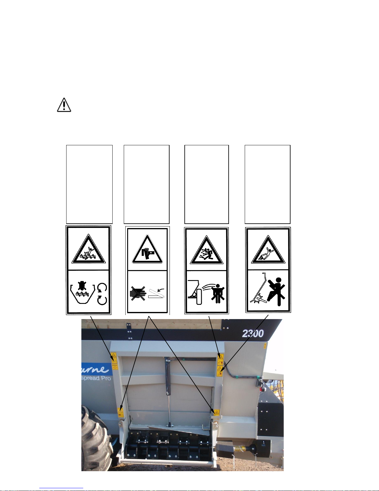
2.2 SAFETY SIGNS
The following safety signs appear on the machine, they provide important instructions
for safe work. –Take them into consideration for your safety and the safety of others.
Ensure that you identify each symbol and understand its warning.
Attached to the PTO guards are additional safety signs, refer to the driveshaft operators
manual for their meaning.
These safety signs must be kept in a legible condition and must be replaced if
missing or damaged. This is especially the case when whole sections are
replaced when making repairs. Replacement safety signs are available as spare
parts through your dealer or importer.
SAFETY SIGNS
800215 01
There is a crushing
hazard, between the
frame of the
impeller and the
door frame of the
tub when
hydraulically raising
the impeller
assembly.
590479 01
Beware of rotating
auger. Do not reach
or lean into tub. Do
not attempt to clear
blockage when the
tractor engine is
running. Serious
injury may result
from falling into the
tub with auger
rotating.
(Also located on LH
side & rear of
machine)
590476 01
Do not use safety
rail on the impeller
as a step. Serious
injury may result
from slipping or
falling into the
impeller.
590477 01
Ensure there are
no persons
standing in the
vicinity of the
machine when the
tractor engine is
running. Serious
injury may result
from rotating parts
and flying objects.
800215 01
There is a crushing
hazard between the
frame of the
impeller and the
door frame of the
tub when
hydraulically raising
the impeller
assembly.
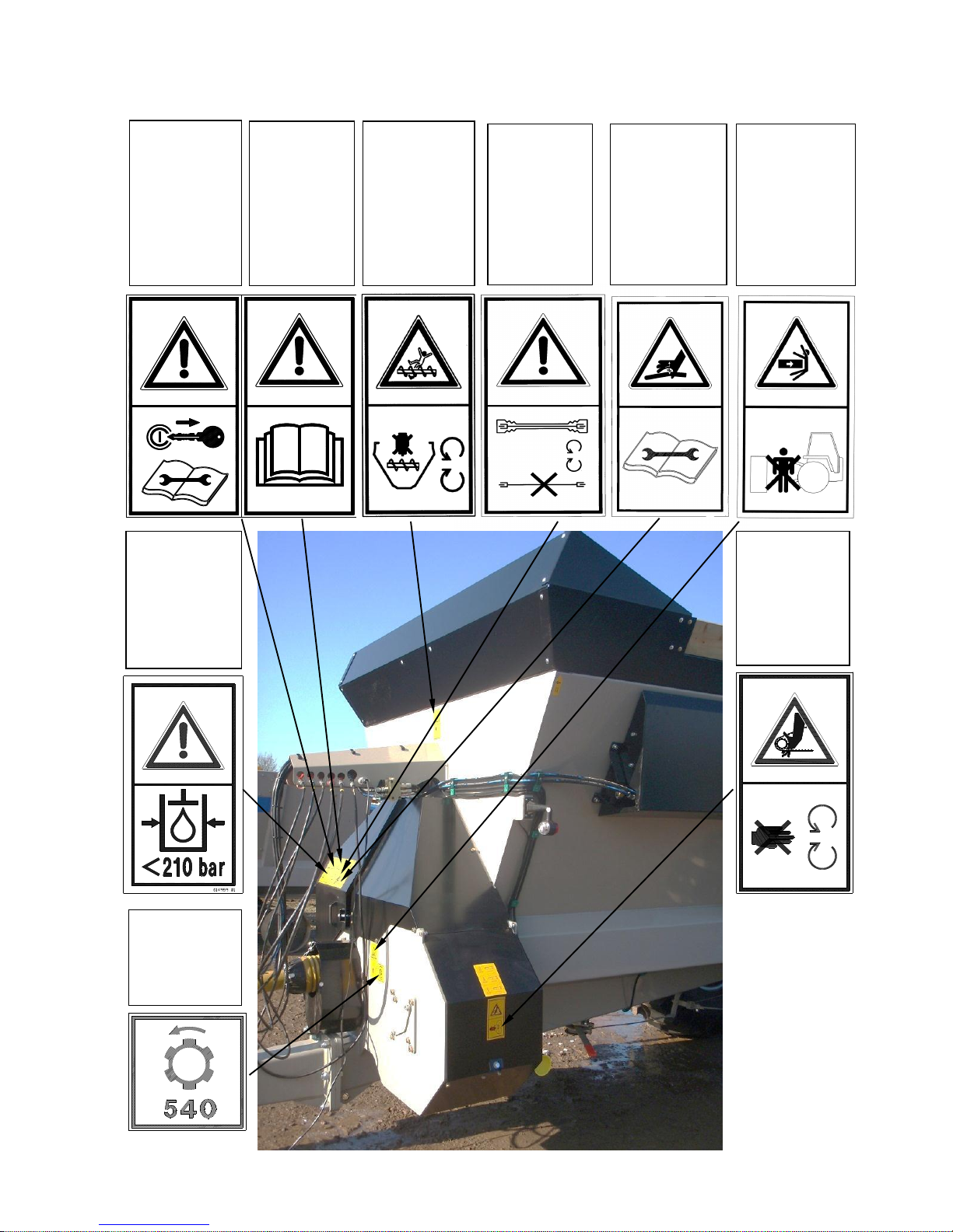
11
TNF-0011
Carefully read the
operating manual
before handling
the machine.
TNF-0011
Stop the engine
and remove the
key from the
tractor‟s ignition
before carrying out
any work on the
machine.
590475 01
The rotational
speed of the PTO
Drive shaft must
not be greater than
the speed stated.
614959 01
Ensure hydraulic
components are not
exposed to more
than 210bar of
pressure. There is a
risk of explosive
damage to hoses
and other
components.
800221 01
Hydraulic oil is
dangerous when
under pressure and
can be injected into
the body. Always
ensure the hoses
are in good order
before operating.
260060 01
Risk of crushing
torso. Do not stand
between
Powerspread and
tractor when hitching
to tractor.
590479 01
Beware of rotating
auger. Do not
reach or lean into
tub. Do not attempt
to clear blockage
when the tractor
engine is running.
Serious injury may
result from falling
into the tub with
auger rotating.
193392 01
Do not open or
remove safety
guard while engine
is running. There is
a risk of hand
entanglement.
193391 01
Ensure PTO shaft
guards are fitted
and chains
attached.

12
2.3 ACCIDENT PREVENTION BEFORE STARTING THE MACHINE.
Read the manual thoroughly.
If moving the Powerspread by overhead lifting, use the designated lifting points. (See
section 4.1). Ensure that the slings / chains are rated accordingly, and that the angles of
the slings / chains are set in accordance to lifting regulations.
Ensure bystanders are at a safe distance when the Powerspread is being suspended
above the ground while lifting and unloading.
Pay particular attention to the width of the machine while unloading the machine from
the delivery trailer. A portion of the tyre may overhang the bed of the trailer, so care
must be taken to keep the machine central, whilst moving.
Ensure bystanders are at a safe distance while moving the Powerspread from the
delivery trailer using a tractor.
Ensure the hydraulic brakes are attached to the tractor before attempting to move the
Powerspread.
Ensure a suitably sized tractor is used to move the Powerspread.
Ensure the tractor is fitted with Mirrors to guarantee the lateral visibility on both sides of
the machine.
Ensure the machine is parked on a firm & level site and the handbrake is applied.
Do not carry out any PDI work without appropriate protective clothing and long hair tied
back. (Gloves, safety boots, close fitting clothing etc.)
Review the PDI checklist, printed at the start of this manual. Check the items listed. Pay
particular attention to checking wheel nuts & tyre pressures, along with checking the
hydraulics and braking systems.
Before adjusting the position of the tow eye ensure the machine is parked on a firm &
level site, with the handbrake applied. Ensure the machine is uncoupled from the tractor
and is sitting securely on the parking foot. The tow eye weighs 35kg; therefor suitable
lifting apparatus is advisable to take the weight while the fixing bolts are removed.
If the length of the PTO shaft needs adjusting always follow relevant workshop & power
tool health and safety procedures / guidelines.
Follow appropriate manual handling procedures, when lifting PTO shaft.
Check there are no foreign objects inside the machine.
Always perform an internal inspection inside, around and under the machine before
attempting to start, transport or load the machine.
The Powerspread may be used only if all safety devices, e.g. detachable guards, are
fitted and in proper working order.
Familiarise yourself with the controls and functions of the machine and practice them in
a safe location before attempting to start work.

13
2.4 ACCIDENT PREVENTION WHEN COUPLING AND UNCOUPLING TO THE
TRACTOR.
The work of coupling and uncoupling the Powerspread involves a high risk of injury
Follow the procedure described in section 5.4 for further information.
Ensure the pickup hitch of the tractor is rated to withstand the maximum load seen at
the drawbar, and that it matches the drawbar eye of the Powerspread.
Ensure the max permissible rear axle load of the tractor will not be exceeded by the
weight of the Powerspread.
Ensure the machine is parked on a firm level site for attaching and detaching, ensure
the handbrake of the Powerpsread is applied.
Check that all observers are clear of the Powerspread and tractor. Warn bystanders by
sounding the horn of the tractor several times.
Slowly drive the tractor towards the Powerspread –always ensure that there are no
other persons in the vicinity or between the machine and the tractor.
Connect the Powerspread to the tractor hitch using only the method recommended in
the tractor‟s operator manual.
Ensure there is sufficient clearance between the PTO shaft and the drawbar when
turning on undulating ground.
Ensure the machine is parked on a firm & level site, and the „safe stop‟ procedure is
followed before raising / lowering the parking foot. This is to ensure that the unit does
not unexpectedly move while the operator or person is in close proximity to the machine
Be aware of the pinch point between the parking foot and the drawbar while raising the
parking foot.
Never leave the driver seat whilst the tractor or machine is running.
Ensure the machine is parked on a firm & level site and the „safe stop‟ procedure is
followed before checking the operation of the rear road lights and before connecting /
disconnecting the power supply. This is to ensure that the unit does not unexpectedly
move while the operator or person is in close proximity to the machine.
2.5 ACCIDENT PREVENTION WHEN USING THE HYDRAULIC SYSTEM
Ensure the machine is parked on a firm & level site and the „safe stop‟ procedure is
followed before connecting / disconnecting the hydraulic couplings. This is to ensure
that the unit does not unexpectedly move while the operator or person is in close
proximity to the machine.
Do not connect to tractor‟s hydraulic system if it can deliver more than 210 bar.
Due to the possibility of oil contamination on your hands / contact with hot or
pressurised oil, it is recommended to use PPE (Personnel Protective Equipment), when
handling hydraulic hoses & connectors.
Do not connect the hydraulic hoses to the tractor‟s hydraulic system until you have
made sure that the system is at zero pressure on both the tractor and the Powerspread.
Do not check the hydraulic system for leaks unless the system is at zero pressure.
This manual suits for next models
1
Table of contents
Other Shelbourne Farm Equipment manuals


Popular Farm Equipment manuals by other brands


MacDon
MacDon NEW HOLLAND D2 Series Unloading and assembly instructions

GREAT PLAINS
GREAT PLAINS TURBO-TILL II Series Predelivery Manual

Precision Manufacturing Inc.
Precision Manufacturing Inc. Add-A-Grapple Operator's manual

Knight
Knight 1800V Series Operating and maintenance manual

Monosem
Monosem TFC 2 user manual

DeLaval
DeLaval SCB3 Instruction book