Baltic BALTIMATIC HAY TEDDER User manual

BALTIMATIC
®
– 2 ROTOR HAYTEDDER
INSTRUCTION & PARTS

OWNERS MANUAL/INSTRUCTION
AND
SPARE PARTS CATALOGUE
BALTIMATIC
®
HAY TEDDER
1.
INTRODUCTION...........................................2
2.
APPLICATION OF HAY TEDDE
R..............................2
3.
SAFETY AND WARNINGS
3.1
general safe y rules.................................2
3.2
labels...............................................4
4.
INFORMATION REGARDING OPERATION OF TEDDER
4.1
General informa ion............................
......5
4.2
Cons ruc ion and opera ion of edder.................5
4.3
Technical parame ers.................................6
4.4
Equipmen ............................................7
4.5
Prepara ion of rac or for work wi h edder..........7
4.6
Prepara ion of edder for wo
rking....................7
4.7
Moun ing hay edder o rac or.......................8
4.8
Adjus men and regula ion of edder..................9
4.9
Opera ion of edder..................................9
4.10
Transpor a ion......................................10
5.
TECHNICA
L SECTION
5.1
Main aining hay edder in good condi ion............10
5.2
Pos season main enance.............................10
5.3
Greasing ins ruc ions...............................11
5.4
Moun ing V
-
bel .....................................11
6.
STORAGE OF HAY TEDDER..
...............................12
7.
PULL TYPE ATTACHMENT..................................13

Page 2.
1. INTRODUCTION
Delivered together with
BALTIMATIC
®tedder, is owner’s manual and spare part catalogue.
This booklet gives the basic information about construction, operation and regulation of tedder.
Owner’s manual is an integrated part of the machine and should be given to operator.
Carefully use of instruction will ensure long term, non problematic use of
BALTIMATIC
®tedder.
In owners manual is used warning symbols to emphasize the importance of information.
This symbol indicate important information regarding safety matters.
If you see this symbol be aware of danger and read carefully the relevant
information and if necessary pass this information on to operator.
Disregarding precautions marked with this symbol can cause danger for
the operator and other persons. Always follow these precautions.
BALTIMATIC
®Tedder has serial plate situated in front of machine. On that plate is written basic
information identifying the machine.
Used n owners manual:
‘‘Left’’ means left s de n dr v ng d rect on
'' R ght’’ means r ght s de n dr v ng d rect on
2. APPLICATION OF BALTIMATIC
®
HAY TEDDER
Machine is designed only for agricultural fieldwork.
To use
BALTIMATIC
®tedder for other applications is not allowed.
BALTIMATIC
®Tedder should be operated, serviced and repaired only by persons
knowledgeable about safety rules for work with and on such machines.
Mod f cat on and changes to the tedder made by operator s not allowed.
BALTIMATIC
®Hay Tedder is designed for tedding hay and straw.
Slightly dried fresh grass in order to accelerate drying process.
BALTIMATIC
®Hay tedder will spread cut hay / straw equally thereby increasing the drying
process of hay/straw.
3. SAFETY AND WARNINGS
3.1. Overall secur ty regulat ons
ATTENTION / CAUTION
In order to avoid danger before work with
BALTIMATIC
®tedder
read carefully owners manual and respect the rules specified there:

Page 3.
*Securing of
BALTIMATIC
®hay tedder lift pins to tractors lift arms should be done only
by using typical safety parts like linch pins.
*Support leg of frame is an integral part of machine. It is not allowed to remove support leg.
*Check always before work with
BALTIMATIC
®tedder position of support wheels. Check
always before parking of teder the position of support wheels and support leg.
*
BALTIMATIC
®Hay tedder should be lifted up smoothly, without rapid move.
*Transport of machine can start after the correct connection of machine with tractor and
lifting up to transporting level.
*
BALTIMATIC
®Hay Tedder transported on hitch system of tractor on public roads must
be equipped with warning lights and triangle plates – relevant to local regulations.
*Every time before work of machine, check the conditions of bolted connections of spring
fingers to the arm and arms to disc of belt pulley.
*During work of
BALTIMATIC
®Tedder it should not be over weighted by additional
weight.
*It is not allowed work w/o shield for PTO shaft and rotor barriers
*Ensure that no one person or animals are near machine during work.
* Maximum allowed PTO rotation is 540 rpm
*Always
pr or
making left/right turns and
pr or
driving backwards
d sconnect
PTO power and
l ft up
tedder.
*It is not allowed driving backwards when machine is in working position
*Maximum allowed slope during work with tedder is 12 degree
*Tractor working with
BALTIMATIC
®Tedder must be equipped with standard front
weights
*Removing of materials and objects from the machine must only be done
when tractor engine is turned off and when machine is lowered to the ground.
*Special attentions when
BALTIMATIC
®tedder is mounted to tractor should be observed
during turning, during transport and when driving backwards.

.
Label eaning Location on machine
ATTENTION Warning against
ROTATING ELE ENTS rotating elements On left side of main frame
book.
Prior work with machine.
Please read instruction Rear part of main frame.
book.
Turn off tractor engine and
remove key PRIOR On right side of main
making frame.
repair or maintenance
work on the haytedder
Throwing elements. On rear frame next to
Keep safe distance from left side rotor
machine
Throwing elements. On rear frame next to
Keep safe distance from right side rotor
machine
Awareness of
support in
- working position On frame above support
- parking position
Left On left belt pulley
direction of rotation
Right On right belt pulley
direction of rotation
Left On left and right support
Right wheels
Information about PTO On shield for input shaft
shaft. Direction and speed for PTO shaft.
of rotation
R
L
Page 4.
*Storing of
BALTIMATIC
®Hay Tedder should take place on level and stable surface
sheltered.
PTO shaft after d sconnect on from tractor should stay on mach ne.
*Dismounting of
BALTIMATIC
®Hay Tedder from tractor can be done only after tractor
engine is stopped and key is taken out.
FAILURE IN FOLLOWING ABOVE RULES CAN CREATE INJURY OF PEOPLE,
DAMAGING OF TEDDER AND OTHERS. THE ENDUSER IS RESPONSIBLE FOR ANY
INJURIES IF RULES ARE NOT RESPECTED.
3.2 Safety s gns and labels
In table 1 is specified markings/labels situated on machine and their meaning.
Labels should be kept in condition that information all time is readable and not is lost.
None readable labels should be replaced by new ones.
New labels can be supplied no charge by request to distributor/producer.

.
.
Page 5.
4 INFORMATION REGARDING OPERATION OF BALTIMATIC
®
TEDDER
4.1. General nformat on
BALTIMATIC
®Hay Tedder with two rotors is a 3 point hitched machine adjusted for work at
slopes no more than 12 degree and working with tractor class 0.6 and higher. Tractor should be
equipped with standard front weights. For driving of
BALTIMATIC
®Tedder should be used
standard PTO shaft with 1 3/8’ spline in both ends. 130 NM transferring power 8KW.
4.2. Construct on and work of BALTIMATIC
®
Hay Tedder
It is a 3 point hitched machine, getting power from PTO shaft.
The layout of 3 point hitched points is acc. To norm ISO 730 1 & AC1: 1996.
BALTIMATIC
®Hay tedder is built from frame (1) to which are fixed working
assemblies/components. Working components are rotating elements (2) to which are fixed arms (3)
with doubled spring fingers (4). The power for rotating elements is coming via PTO shaft, pulleys
and V belts. Belt pulley with spring fingers rotate in opposite direction. Spring fingers touch the cut
grass / straw turning it. Support wheels (5) are following the ground to ensure even ground
clearance for spring fingers. To the frame of machine are bolted safety barriers (8) preventing
access to rotating working elements. To barriers are welded clamps (9) for fixing lights warning
plates (10) and triangle plate (11) (ACC. TO NOMR PN 93/r 36154
BALTIMATIC
®
HAY TEDDER WITH TWO ROTATING ELEMENTS
1. 1 HITCHED FRAME, 2 ROTATING ELEMENT, 3 ARM, 4 SPRING FINGER
5 SUPPORT WHEEL, 6 SUPPORT, 7 PTO SHIELDS, 8 SAFETY BARIERE
2.
8.
3.
4.
5.
7.
1.
……………
……………………………………………………………………………………..

Page 6.
4.3Techn cal character st c
TECHNICAL DATA FOR 2 -ROTORHAYTEDDER
DI ENSIONS US US
Length mm inch 1460 57½"
Width mm inch 2610 102,75"
working width mm inch 2700 106 1/3"
Height m Inch 1200 47 ¼”
WEIGHT kgs lbs 120 264
POWER REQUIR ENT kW kW 8-10 08- 10
TRACTOR REQUIRE ENT
Class in. 0.6
Power kW kW 23-33 23-33
ROTOR SPECIFICATIONS
Axle spacing mm inch 1350 53 1/6"
Diam rotors mm inch 1260 49 1/2"
GROUND CLEARANCE TRANSPORT mm inch min 300 in 12"
NU BER OF GREASING POINTS pcs. pcs. 4 4
ROTOR REVOLUTIONS rpm rpm 340 340
.
DRAWING 2.
SCHEMA OF DRIVE OF BALTIMATIC
®
TEDDER
A/ OVERALL VIEW FROM
FRONT
B/VIEW FROM THE TOP
1 – PTO SHAFT
2 – INPUT SHAFT TO
POWER PULLEY
3 – POWER PULLEY
4 – V-BELT
5 – LEFT PULLEY
6 – RIGHT PULLEY
7 – TIGHTENER PULLEY

Page 7.
US US
AXI U TRANSPORT SPEED km/h miles/h 9.2 6
WORKING SPEED km/h miles/h 6 - 12 4 - 8
SUPPORT WHEEL SYSTE
Number of wheels pcs. pcs. 2 2
spacing of wheels mm inch 1400 55 1/6"
Dimensions – diam mm inch 380 15“
Dimensions – width mm inch 160 6 1/3”
POWER TAKE OF SHAFT – PTO
Power size Nm Nm 210 210
Nominal transmission of power kW kW 12 12
Lenght mm inch 460 18 1/6"
Yoke ends splined splined 6 6
Revolution rpm rpm 540 540
4.4 Equ pment
With
BALTIMATIC
®Hay Tedder should be supplied owners manual with instructions and
sparepart catalogue.
4.5 Preparat on of tractor to work w th BALTIMATIC
®
hay tedder
Preparation of tractor to work with
BALTIMATIC
®Hay Tedder should be made in
accordance to general instruction in owners manual for the tractor.
Lift arm pins on the tractor should be adjusted to same height as the lift arm pins on the
tedder. That will make it easier to mount
BALTIMATIC
®tedder to tractor.
4.6Preparat on of mach ne for work
Check
BALTIMATIC
® tedder that it is in correct technical condition.
Check bolt connections of springs to arms
Check bolt connections of arms to belt pulley
Check springs for wear and broken springs
In case of worn or damaged springs these must be replaced
Check condition of V belt, if damaged or worn out it should be
Replaced with a new one.
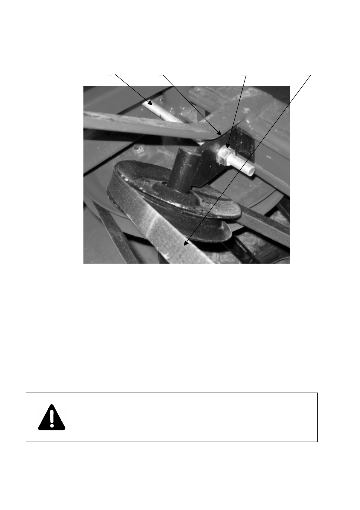
Check the tension of V Belt. Belt must not be loose.
If regulation of tension is necesserary it can be done by nut (3) on
drawing 3. The slack of the V belt between belt pulley and tightnere
should be approx 6’ when a force of 110 lbs is applied to the V belt.
Checking if support wheels are turning slightly, without stopping
Mount PTO shaft on machine.
Remember every time before wor , to chec technical
condition of spring fingers, bolt connections of springs to
arms and bolt connections of arms to belt pulley.
.

Page 8.
Draw ng 3. Regulat on of t ghten ng of belt:
1/t ghten ng bolt, 2/t ghtener, 3/regulat on nut, 4/V-belt
1. 2. 3. 4.
.
4.7Mount ng BALTIMATIC
®
Hay Tedder to tractor
Mounting of
BALTIMATIC
®Hay Tedder to tractor should be done in following steps:
Disassembled draw bar from lower lift arms. Drive tractor close to frame of Hay Tedder
Stop tractor, use hand brake, turn off tractor engine and take out tractor key.
Mount top link to top of 3 point hitch on tedder and secure by using linch pins. Lift up lift
arm supports of frame on tedder – mount these to lift arms on tractor and secure by linch
pins. Tighten side chains of lower lift arms on the tractor.
Mount PTO shaft to
BALTIMATIC
®Hay tedder and to tractor. ( Tractor side on shaft is
outside pipe, Tedder side on shaft is inside pipe).
Secure chains of shield of PTO shaft to shield of machine shaft and tractor.
ATTENTION it is prohibited to mount hay tedder to tractor
at the same time tractor us running. Turn off tractor and
remove ey prior connecting
BALTIMATIC
®
hay tedder to
tractor.
.

.
Page 9
4.8 ADJUSTMENT OF BALTIMATIC
®
TEDDER
Before operation and working with
BALTIMATIC
®tedder it is necessary to make proper
adjustments of the tedder. Correct adjustments of spring fingers and adjustments of working
angel of the rotors.The control of correct adjustment of spring fingers should be done at the
same time when damaged spring fingers are replaced or tightened. In order to adjust finger
correctly it is necessary to use 90 degree angel bar (pos. 1 on draw. 4) In order to make
regulation please make loose on fixing bolt (4 on drawing 4) Put angel bar on rotor arm acc.
to drawing 4. Distance from end of spring finger to the range of angle bar should be from
1½” – 4” (40 up to 100mm). Fingers should be adjusted equally on all arms of both rotors.
Draw ng 4.
Correct adjustment of spr ng f ngers:
1 – angel bar
2 – rotor arm
3 – spr ng washer
4 – nut bolt
5 – spr ng f nger
In order to achieve the proper working angel of rotors from the ground, it is necessary to
adjust toplink on tractor whereby the front spring fingers on the rotors will be situated
1 / 4” – 1 / 3” (4 – 10) mm over the ground.
4.9 – operat on of BALTIMATIC
®
hay tedder
Newly cut grass is after been cut laying on the ground on the field – sometimes in a
windrow. In the drying process the grass is tedded 3 4 times during a day. Tedding should be
done during weather condition where the humidity is low. Frequent tedding enables the grass
to dry quicker.
BALTIMATIC
®Hay Tedder should enter the windrow of grass only when
full RPM of the working rotors is achieved (rotation speed of tractor shaft 540 rpm).
During work it is recommended to find level of RPM on engine which will give speed in range of 6
12 km/h and which will give RPM of engine which refers to nominal rotation of PTO shaft. Speed
should be selected dependly on land condition and the quantity of grass/straw in the windrow. All
material, which makes the machine to clough, should be removed when Hay Tedder is in lower
position (on ground) and engine of tractor is OFF

.
Page 10
Before start, be sure that no one is near
or around the machine & tractor.
During wor do not allow people to be
close to machine.
All service and repair wor should be
done only when
BALTIMATIC
®
Tedder is in
lower position on the ground and and the
engine of tractor is OFF.
ATTENTION:
It s not allowed to dr ve backward w th tractor dur ng work,
when mach ne s n work ng pos t on.
BALTIMATIC
®
Tedder
should be l fted smoothly w thout rap d moves.
4.10 Transport
Hitched Hay tedder with two rotors when transported on public roads should be equipped with
warning lights and triangle warning plates – relevant to local regulations.
During transport,
BALTIMATIC
®Hay Tedder should be lifted up, to position ensuring
required ground clearance.
When making turns on the road keep attention to on the length of the vehicle (tractor and
hay tedder). It is not allowed to have any persons riding on the hay tedder during transport.
5. TECHNICAL SECTION
5.1 Ma nta n ng BALTIMATIC
®
hay tedder n good cond t on
In order to keep hay tedder in good condition every time after work is finished, the
BALTIMATIC
® Hay tedder should be cleaned from the rest of plants.
All bolts / nuts should be checked for not being missing or loose.
All moving parts should be checked.
Parts being damaged or being worn out should be renovated or replaced with new parts.
5.2 Post - seasonal serv ce.
When season is finished,
BALTIMATIC
®Hay tedder should be carefully cleaned. Worn or
damaged working elements should be replaced and all loose bolts/nuts should be tightened.
Tightener for V belt should loosen.
BALTIMATIC
®Tedder should be greased acc. To
greasing instruction. Places where paint is removed/ damaged should be cleaned and covered
by new paint.

Page 11
5.3 Greas ng nstruct on
Please keep the relevant greasing periods mentioned in table 3.
Prior greasing all greasing point – greasezerks should be cleaned.
5.4 Mount ng V-belt
Place the V belt down on the ground
Belt should be placed as shown on drawing 5. Having shape of number 8
Drive backward with the tedder machine toward the belt on the ground
as shown on drawing 5.
Mount V belt according to drawing 2. (page 6).
While mounting V belt move/turn the belt pulleys
in opposite direction than the pulleys are turning during ordinary work.
Put attention to that V belt after mounting has the correct position
tighten belt by using tightener. The slack of the V belt between belt pulley and
tightnere should be approx 6’ (15 mm) when a force of 110 lbs (50 N) is applied to the
V belt.
Draw ng 5. Preparat on of belt for mount ng on mach ne
.
.
TABLE 3. GREASING PLACES
LOCATION OF GREASE ZERKS FREQUENCY TYPE OF GREASE
Hubs of wheel holder for driving wheels Each 20th. Hour of work LT- 43
Bushings/bearings on wheels Each 20th. Hour of work LT- 43
End of PTO shaft After daily work LT- 43

Page 12
6. Stora
ge of
BALTIMATIC
®
Hay Tedder
Hay tedder should be stored under roof on level, solid ground.
The PTO input shaft on the tedder and bolt on belt tightener should be covered with solid
grease.
In case machine is stored long
time outside, conservation/preservation of these elements
should be repeated during the storage period in case the protective grease
coating is wearing off.
BALTIMATIC
®
Hay Tedder should be stored in place where there is no danger for any
persons.

Page 13
7. PULLTYPEATTACHMENT FOR BALTIMATIC ® HAYTEDDER
Pulltype attachment enables user to convert 3 point hitch haytedder to a pull type version tedder.
IMPORTANT: Wheel adjustment.
The wheels on haytedder in 3 point hitch version is unlocked and should be able to swivel freely.
The wheels on haytedder in pull type version MUST be fixed and locked.
On wheel holder bolt for locking the wheels must be tightened.

P
age 14
FRAME WITH TIGHTENER
.
Pos. No.
Part
Description
Part
number
pcs.
1
Frame
8 8245-525-001-002
1
2
Support
8245-525-001-00
5
2
3
Pin for
support
8245-525-001-004
2
4
Hair pin
BN-81/1902-04
2
5
Tightener for V-
belt
8245-525-001-007
1
6
Bolt for
tightner
8245-525-001-00
6
1
7
Nut 12
PN-86/ -82144
2
8
Washer 13
PN-76/ -
82005
2
9
Belt
pulley
8245-525-001-
001
1
10
Circlip z 20
PN-81/ -
85111
1
11
Bearing
62052RS
PN-85/ -
86100
1
12
V-belt
C5000
PN-86/ -
85200/86
1

P
age 15
ROTORS
.
Pos. No.
Part
Description
Part
number
pcs.
1
Axle for
rotor
8245-525-002-001
2
2
Belt pulley for
rotor
8245-525-002-
002
2
3
Rotorar
m
8245-525-002-
003
10
4
Spring
8245-525-002-
004
10
5
Bolt
12x45
PN-85/ -
82105
10
6
Washer
13
PN-78/ -
82005
30
7
Nut
12
PN-86/ -
82144
30
8
Compression
washer
8245-525-002-
005
10
9
Bolt 12x
30
PN-85/ -
82105
20
10
Wheel holder
left
8245-525-003-
001
1
11
Grease zerk
10
PN-76/ -
86002
2
12
Bolt 16 x
35
PN-85/ -
82105
4
13
Washer
8245-525-002-
006
4
14
Spring washer
16.5
PN-77/ -
82008
4
15
Plate
8245-525-002-
007
2
16
Ball Bearing
60072RS
PN-79/ -
86100
4

PAGE 16
1111615
SUPPORT WHEEL
Pos.
No.
Part
Description
Part
number
pcs.
1
Left wheel
holder
8245-525-003-002
1
2
Right wheel
holder
8245-525-003-003
1
3
Rubber
Wheel
8245-525-003-004
2
4
Axle for
wheel
8245-525-003-005
2
5
Greasing zerk
10
PN-76/ -86002
4
6
Bolt
10x25
PN-85/ -82105
2

Page 17
CONNECTOR
Pos. No.
Part Description
Part number
pcs.
1
Bushing
8245-525-004-001
1
2
Input shaft
8245-525-004-002
1
3
Belt pulley
8245-525-004-003
1
4
Ball Bearing 60072RS
PN-79/ -86100
2
5
Bolt 10 x 30
PN-85/ -82105
6
6
Nut 10
PN-86/ -82144
6
7
Spring washer 10.2
PN-77/ -82008
6
8
Nut 20
PN-86/ -82144
1
9
Spring washer 20.5
PN-77/ -82008
1
10
Prism key B7x8x26
PN-70/ -85005
1
11
PTO cover
21902
1

P
age 18
SCREENFOR RIGHT
ROTOR
Pos. No.
Part Description
Part number
pcs.
1
Screen for Right rotor
8245-525-006-001
1
2
Washer 10.2
PN-78/ -82005
7
3
Nut 10
PN-86/ -82144
5
4
Bolt 10 x 20
PN-85/ -82105
2

Page 19
SCREENFOR LEFT ROTOR
Pos. No.
Part Description
Part number
pcs.
1
Screen for Left rotor
8245-525-005-001
1
2
Washer 10.2
PN-78/ -82005
6
3
Nut 10
PN-86/ -82144
4
4
Bolt 10 x 20
PN-85/ -82105
2
Table of contents