Shenzhen Prunus Medical Boaray 2000C User manual

I
Product Information
Product Name:Ventilator
Product Model: Boaray 2000C, Boaray 2000D
Version Information
The version number ofthis user manual may be updated due to the software
upgrades; Shenzhen Prunus Medical Co., Ltd. reserves the right to change it without
giving prior notice.
The version information:
Version No.: M93-P-00224-8.0
Release date: October 2019

II
CE Mark
Well Kang Limited (www.CE-marking.eu)
The Black Church, St. Mary's Place, Dublin 7, D07 P4AX, Ireland
This product bears a CE mark, as it conforms to European Council Directive for Medical
Devices (93/42/EEC), and meets the essential requirements of AnnexⅠof the directive.
This product meets the requirements of EN 60601-1-2 standard “Medical electrical
equipment - Part 1-2: General requirements for basic safety and essential performance -
Collateral Standard: Electromagnetic disturbances - Requirements and tests”.
Declaration
The intellectual property of the product and its document belongs to Shenzhen Prunus
Medical Co., Ltd. (hereinafter referred to as PRUNUS). PRUNUS reserves the final right of
interpretation for this document. Any unauthorized copying, storage, reproduction or
translation of this document in any form is strictly prohibited without the prior written
permission from PRUNUS.
Users can, if needed, ask for other technical information separately from PRUNUS in order
to understand, operate and maintenance the equipment, but should ensure the information
not obtained by the third party.

III
User’s Responsibility
Please check the product and accessories firstly when you receive the product, make sure
it conforms to the contract. If any damage to the package or the product is found before or
after opening the packing case, please contact the local office or the franchiser
immediately.
Users must perform the installation, operation, maintenance and carry out regular
inspection according to the instruction described in the manual. Replace the components
immediately if any damage, loss, distortion or contamination is found. Stop use when
malfunction occurs. Please contact the after service department of PRUNUS for repairing
and replacing. Any change of the product is verboten without agreement from PRUNUS.
The user must take responsibility for any malfunction which results from non-compliance
with the servicing requirements detailed in this manual or the service or repairs are not
performed by the personnel of PRUNUS.
Free Maintenance
The user reserves the right to be served for free repairs and replacement within 12 months
from the order delivered date only in the event that the product is purchased from PRUNUS
or the authorized distributor, it must be a new product when purchased and it is operated
according to the “User’s Responsibility”. Otherwise, PRUNUS has no responsibility for any
damages to the product.
Trademarks
, and are trademarks or registered
trademarks of PRUNUS.

IV
Preface
Description
This manual describes the intended use, function, installation, operation and maintenance
of the product. Personnel must make themselves familiar with the contents of this manual
and the machine’s function before using the apparatus. When you begin to use the
ventilator, we consider that you have read the manual carefully.
In order to use the equipment accurately, effectively and avoid the accident, please read
the manual carefully and comply with it strictly, especially pay attention to the “Warning”,
“Caution” and “Note”.
The optional features may not be completely included in the manual, should you have any
questions, please contact PRUNUS.
Please put the manual near the product so that you can easily fetch it at any time.
Illustration
The illustrations in the manual are only for reference, some settings and data may not be
consistent with the real display of the product; please refer to the real product.
Conventions
Bold Italic: The quoted section.
【
Character
】
: The character string on the software interface or in the control panel.

V
Contents
Product Information ................................................................................................................I
After Service ...........................................................................................................................I
Version Information ................................................................................................................I
CE Mark.................................................................................................................................II
Declaration ............................................................................................................................II
User’s Responsibility ............................................................................................................III
Free Maintenance.................................................................................................................III
Trademarks...........................................................................................................................III
Preface ................................................................................................................................ IV
1 Safety Information ..............................................................................................................1
1.1 WARNINGS..................................................................................................................... 2
1.2 CAUTIONS ...................................................................................................................... 6
2 Equipment Description .......................................................................................................9
2.1 INTRODUCTION ............................................................................................................... 9
2.1.1 Intended use ......................................................................................................... 9
2.1.2 Applications ........................................................................................................ 10
2.1.3 Contraindications ................................................................................................ 10
2.1.4 System composition ........................................................................................... 10
2.1.5 Features.............................................................................................................. 11
2.2 SYSTEM OVERVIEW ...................................................................................................... 11
2.2.1 External pipeline connection diagram ................................................................ 12
2.2.2 Front view ........................................................................................................... 13
2.2.3 Rear view............................................................................................................ 14
2.2.4 Bottom view ........................................................................................................ 15
2.3 POWER SUPPLY ............................................................................................................ 15
2.4 BATTERY ...................................................................................................................... 16
2.5 GAS SUPPLY................................................................................................................. 18
2.6 SYSTEM SWITCH........................................................................................................... 18
2.7 MEMBRANE BUTTONS.................................................................................................... 19
2.8 SCREEN DISPLAY.......................................................................................................... 22
2.9 VENTILATION MODES..................................................................................................... 23
2.9.1 A/C (V) mode ...................................................................................................... 23
2.9.2 A/C (P) mode ...................................................................................................... 24
2.9.3 SIMV mode ......................................................................................................... 24
2.9.4 SPONT mode ..................................................................................................... 25
2.9.5 PRVC mode........................................................................................................ 26
2.9.6 CPAP mode ........................................................................................................ 26
2.9.7 DualPAP mode ................................................................................................... 27

VI
2.9.8 Backup ventilation mode .................................................................................... 28
2.10 ALARM SYSTEM............................................................................................................ 28
2.10.1 General description ............................................................................................ 28
2.10.1.1 Alarm categories......................................................................................................28
2.10.1.2 Alarm priorities.........................................................................................................29
2.10.1.3 Alarm signals...........................................................................................................29
2.10.1.4 Alarm information and priority..................................................................................30
2.10.2 Alarm silence ...................................................................................................... 31
2.10.3 Alarm limit setting ............................................................................................... 32
2.10.4 Alarm volume setting .......................................................................................... 32
3 Disassembling and assembling........................................................................................33
3.1 BATTERY MODULE......................................................................................................... 33
3.2 OXYGEN SENSOR ......................................................................................................... 33
3.3 PATIENT SYSTEM........................................................................................................... 36
3.4 EXHALATION VALVE ....................................................................................................... 37
3.5 GAS SUPPLY................................................................................................................. 39
3.6 HUMIDIFIER .................................................................................................................. 39
4Pre-use check ..............................................................................................................42
4.1 SYSTEM CHECK ............................................................................................................ 42
4.2 FUNCTION CHECK ......................................................................................................... 43
4.3 ALARM TEST................................................................................................................. 45
4.3.1 Pre-test preparations .......................................................................................... 45
4.3.2 Airway pressure high alarm ................................................................................ 45
4.3.3 Tidal volume low alarm ....................................................................................... 45
4.3.4 O2concentration low alarm ................................................................................ 46
4.3.5 Circuit disconnected alarm ................................................................................. 46
4.3.6 Battery in use alarm............................................................................................ 46
4.3.7 Tube obstruction alarm ....................................................................................... 46
4.3.8 Tube partial occlusion alarm............................................................................... 47
4.3.9 Oxygen supply pressure low alarm .................................................................... 47
4.3.10 Continuous airway pressure high alarm ............................................................. 47
4.3.11 Apnea alarm ....................................................................................................... 47
5 Operations and Settings...................................................................................................48
5.1 KEYS ........................................................................................................................... 48
5.2 BOOT SELF-TEST .......................................................................................................... 49
5.3 STANDBY SCREEN ........................................................................................................ 49
5.4 PATIENT SETTING ......................................................................................................... 50
5.5 STANDBY ..................................................................................................................... 51
5.6 MAIN SCREEN............................................................................................................... 52
5.7 MODE SETTING............................................................................................................. 55
5.8 SYSTEM SETTINGS........................................................................................................ 58
5.8.1 General settings ................................................................................................. 58
5.8.2 Alarm setting....................................................................................................... 59

VII
5.8.3 System log .......................................................................................................... 60
5.8.4 Biomed................................................................................................................ 61
5.8.5 Version information............................................................................................. 61
5.9 POWER OFF THE VENTILATOR........................................................................................ 62
6. User Maintenance ...........................................................................................................63
6.1 CLEANING AND DISINFECTION ....................................................................................... 64
6.2 MAINTENANCE SCHEDULE ............................................................................................. 68
6.3 VENTILATOR SURFACE .................................................................................................. 69
6.4 EXHALATION VALVE ...................................................................................................... 69
6.5 BREATHING TUBES........................................................................................................ 70
6.6 BATTERY...................................................................................................................... 70
6.7 OXYGEN SENSOR ......................................................................................................... 71
6.8 TURBINE AIR INLET DUST FILTER.................................................................................... 72
Appendix A Working Principle.............................................................................................73
A.1 PNEUMATIC CIRCUIT PRINCIPLE ......................................................................................... 73
A.2 PNEUMATIC CIRCUIT DIAGRAM ......................................................................................... 74
Appendix B Product Specifications .....................................................................................75
B.1 SYSTEM ....................................................................................................................... 75
B.2 TECHNICAL PARAMETERS.............................................................................................. 76
B.3 SETTING PARAMETERS.................................................................................................. 77
B.4 MONITORING PARAMETERS ........................................................................................... 78
B.5 ALARM SETTING PARAMETERS ....................................................................................... 79
Appendix C Alarms..............................................................................................................80
C.1 HIGH PRIORITY ALARMS................................................................................................. 80
C.2 MEDIUM PRIORITY ALARMS............................................................................................ 82
C.3 LOW PRIORITY ALARMS ................................................................................................. 83
Appendix D EMC .................................................................................................................84
Appendix E Glossary and Symbols.....................................................................................92
E.1 GLOSSARY ................................................................................................................... 92
E.2 SYMBOLS ..................................................................................................................... 94
E.3 PACKAGE SYMBOLS ...................................................................................................... 96
Appendix F Default settings ................................................................................................97

1
1 Safety Information
The safety information described in this chapter explains unsafe conditions that may occur
if not performed correctly according to the manual. Please review all the warning, caution
and Note prior to operating the ventilator.
This chapter contains important safety information of the ventilator, and some other safety
information throughout each chapter of the manual. Please read and understand all the
safety information before use to avoid security risks.
If you have a question regarding the installation, set up, operation, or maintenance of the
ventilator, contact the after-service department of PRUNUS.
Warning:
Identify conditions or practices that could result in serious adverse reactions or
potential safety hazards.
Caution:
Identify conditions or practices that could result in damage to the ventilator or other
equipment.
Note:
Identify supplemental information to help you better understand how the ventilator
works.

2
1.1 Warnings
Warnings:
Boaray2000 series ventilator is a restricted medical device intended for use by
qualified, trained personnel. Operations of the equipment should be strictly
according to the user manual.
Only those conform to the latest IEC 60601-1 standard accessories and auxiliary
equipment can be connected to the ventilator. If peripheral equipment such as
computer, monitor or humidifier has been connected to the ventilator, the whole
system should meet the IEC 60601-1 standard.
All analog or digital products connected to this system must be certified passing the
specified IEC standards (such as IEC 60601-1 for medical electrical equipment and
IEC 60950 for safety of information technology equipment). All configurations shall
comply with the valid version of IEC 60601-1. The personnel who are responsible for
connecting the optional equipment to the I/O signal port shall be responsible for
medical system configuration and system compliance with IEC 60601-1-1.
Users have the responsibility to carry out the necessary measure to ensure that the
curing environment is in line with the limited regulation of the IEC 60601-1-2
standard. Operating the equipment beyond the regular limit may cause damages or
security risks to the system. The Preventive measures may include (but not limited
to) the following aspects:
1) More attention should be paid to the relative humidity and conductivity of
clothes to minimize the possibility of the static gathering.
2) Avoid using the wireless radiate devices (such as the mobile phone) or high
frequency devices near the ventilator.
Due to the possible fire or explosion hazard, all the ignition sources must be away
from the ventilator and the oxygen tube. Do not use the oxygen tube which is worn
or effused or contaminated by the flammable liquid (such as grease or oil). In the
environment of high oxygen concentration, textiles, oils and other combustible

3
Warnings:
material are easy to cause fire. When you detect a burning odor, cut off the oxygen
supply device, the power supply and the spare resource immediately.
To avoid personnel injury and the risk of electric shock, as well as damage to the
ventilator, do not operate the ventilator with its covers or panels removed. Refer all
servicing to the service technician certified by PRUNUS.
Care should be taken to ensure that the patient does not disconnect from the
breathing circuit. Such disconnections could be hazardous to the patient.
Do not operate the ventilator without setting the alarms. All alarms must be set to
ensure safe operation.
Do not operate the ventilator unless qualified personnel are in attendance to
promptly respond to alarms, inoperative conditions, or sudden malfunctions.
Patients on life-support equipment should be visually monitored at all times.
Qualified personnel should be prepared to provide an alternate form of ventilation, if
needed.
Alarm sound level should be higher than the ambient sound, so that the monitoring
personnel can hear the alarms.
Before the battery runs out, please use the AC power supply.
Check all audible and visual alarms daily to make sure they are operating properly. If
an alarm fails to active, contact the service technician certified by PRUNUS.
Make sure a backup ventilation plan is always available.
Low air density at high altitudes affects tidal volume delivery and exhaled tidal
volume measurements.
Do not try to service or repair an improperly functioning ventilator yourself. Contact
the service technician of PRUNUS for all repairs and service.
Do not use parts, accessories, or options that have not been authorized for use with
the ventilator. Using unauthorized parts, accessories or options may be harmful to
the patient or damage the ventilator.
Check the exhalation valve diaphragm daily to ensure that it is not worn or

4
Warnings:
damaged. A worn or damaged exhalation valve diaphragm may result in improper
patient ventilation. Replace the diaphragm as necessary.
If mechanical or electrical problems are found during use, you must stop using the
ventilator and contact the qualified service technician for maintenance. Using
improperly functioning ventilator may be harmful to the patient.
The ventilator is not designed for the MR environment that is suitable for the
Medication reaction (MR) checking. Otherwise the system may lose some functions
and it may cause permanent damage to the ventilator system.
This equipment can only be used in the specified environment, and it cannot be
used near the flammable or explosive resources and cannot be used in the mobile
phone, radioactive rays or the MRI equipment environment.
When external devices are attached to the ventilator, it may cause increase of the
leakage current.
Always perform a regular clean and pre-use check after opening the package.
The power cord should be connected to a properly grounded AC electrical outlet to
avoid electric shock.
Not to draw tracheal cannula forcefully, and do not distort and fold the tracheal
cannula in application to avoid unexpected danger.
When attaching accessories, components or assemblies to the breathing system,
the pressure gradient that the breathing system relative to the patient connection
port may increase.
Please double-check the power cord before connected to the electrical outlet, make
sure it has no damage, scratch or other factors which will lead to the inside
conductor exposed issues.
When there is any doubt about the integrality of the outside grounded protection or
the grounded protection cord, the equipment must be replaced with: internal power
supply (battery).
Keep the ventilator upright during use.

5
Warnings:
The ventilator shall not be covered or positioned in such a way that the operation or
performance of the ventilator is adversely affected.
Once any abnormal event occurs, such as the unfamiliar pop-up windows on the
screen, unfamiliar sounds, alarms from the patient device, or high priority
technology alarm occurs, discontinue use of the ventilator and check it at once,
replace the corresponding components as occasion requires.
Set the alarm limit to a proper value in order to ensure patient safety.
Positive pressure ventilation may be accompanied by the following side effects:
barotrauma, hypoventilation, hyperventilation or circulatory injury.
The maintenance is allowed only in the condition that the equipment is not
connected to the patient.
All personnel should be aware that Disassembling or clearing certain parts of the
ventilator may cause infection risk.
The equipment will produce some castoff, the one-off parts or the damageable parts
which will lead to serious pollute or cross infection if discarded randomly, and should
be managed and disposed according to the relative regulations.
When the equipment or the accessories are about to exceed the limit time, they
should be disposed according to the local regulations or the hospital systems.

6
1.2 Cautions
Cautions:
The ventilator must be serviced and checked at regular intervals by professionals
who have received specialized training. Please refer to the chapter 6 for the
maintenance time interval information. All service performed on the ventilator
should be recorded in a service log in accordance with the regulations.
PRUNUS has no responsibility for the safe operation of the ventilator system if
maintenance or repairs are not performed by personnel who are employed or
authorized by PRUNUS.
Users must take the related responsibility for any malfunction which results from the
package or product disassembled by the user.
PRUNUS has no responsibility for the safe operation of the ventilator if it is used in
other field described in the user manual.
The data measured from the signal output port of the ventilator as well as the data
managed by the auxiliary equipment cannot be regarded as the basic of treatment
or diagnosis decisions. Such decisions can only be made by the experienced
medical personnel based on the previous or accepted manner. PRUNUS has no
responsibility for the accuracy of the signal handling if auxiliary equipment not
provided by PRUNUS is used with the ventilator system.
If there are differences between the information displayed on the user interface of
the ventilator and the corresponding information displayed on the auxiliary
equipment, the information on the user interface is considered as the main reason.
It is the user’s responsibility for the integrity and security of the system while using
the accessories or auxiliary equipment not provided by PRUNUS. As for the safety
of the electrical system, only those accorded with the latest IEC 60601-1 standard
accessories and auxiliary equipment could be connected to the signal input and
output interface of the ventilator system.
Only those accessories, spare parts or auxiliary equipment recommended by

7
Cautions:
PRUNUS can be used to be connected to the ventilator system. Otherwise it may
cause damage or security to the system.
Please refer to the assembling instruction described in the user manual to assemble
the system or optional accessories.
The gases used in the system must conform to the following standards for
concentrations of water vapor and oil:
Air: H2O<7g/m3, Oil<0.5mg/m3
Oxygen: H2O<20mg/m3
Pressure value is given in cmH2O:
1kPa = 10cmH2O
100kPa = 1bar ≈1atm ≈1kgf/cm2≈14.5psi
As general rule, always be careful not to touch the pins of the external electric
connector.
The measuring value condition shown in this user manual is ambient temperature
and pressure, dry gas (ATPD) condition.
Sharp tools should be away from the screen.
Accumulation of excess liquid in the expiration sensor is not allowed (such as in
clean and disinfection period, otherwise it may affect the function of the ventilator.
Do not over clean the ventilator. Repeated use of a cleaning agent can cause
residue build-up on critical components. Excessive residue build up can affect
ventilator performance.
When cleaning the ventilator, do not use harsh abrasives. Do not immerse the
ventilator in liquid sterilizing agents or liquids of any kind. Do not spray cleaning
solution directly onto the front panel. Do not allow cleaning solution to pool on the
front panel.
Do not insert cleaning instruments (such as a cloth, brush, or pipe cleaner) into the
flow sensor.
Do not use high pressure gas nozzle to dry the flow sensor, high pressure gas may

8
Cautions:
damage the flow sensor.
When lifting or moving the ventilator system or some parts of the system, please
comply with the instruction of the machine and do some preparation of the safety.
Do not use soft tube with the characteristic of antistatic electricity or the electricity
conducting.
The ventilator contains no latex element.
Make sure there is at least one battery as backup power supply.
Once the system is connected to the patient, make sure there should always be
someone professional to monitor the system operation.
Do not store the ventilator in hot areas for prolonged periods of time. High
temperatures can shorten battery life.
Do not disassemble the expiratory module during operating the ventilator.
Always use a Heat and Moisture Exchanger (HME) or other equivalent equipment
to prevent the dehydration of the lung system.
When disposing of the old oxygen sensor, observe the relevant regulations for
biohazard and do not burn it.
All the disposable components should be disposed according to the hospital
regulations and in an environmental safe way.
Note:
When the system is not used, it is recommended the device is connected to the
main power supply in order to keep the battery power.
If the system is connected to the main power supply, even if the system switch is in
the closed state, the main power supply of the system is not interrupted.

9
2 Equipment Description
2.1 Introduction
2.1.1 Intended use
The ventilator system is an easy to use, turbine-driven, computer controlled ventilator. It
has a color LCD with real time graphics display and digital monitoring capabilities,
membrane buttons and a knob for changing settings. According to the user’s setting, the
ventilator provides air with the preset oxygen concentration to patients with continuous flow
or continuous pressure to control the patients or support ventilation. Doctors can control
the patients timely by real-time monitoring the multi-respiratory parameters of the ventilator
to ensure patients safety and good treatment.
The ventilator is intended for treating and monitoring adult and pediatric patients with
respiratory failure or respiratory insufficiency. The ventilator should be used only in
hospitals or in health care facilities, or during transport of a patient.
The Boaray 2000 series ventilator has two models: Boaray 2000D and Boaray 2000C, the
differences of their configurations are shown as below:
Configurations /Models Boaray 2000C Boaray 2000D
DualPAP / Optional
PEEP 0~30 cmH2O 0~40 cmH2O
VT 50~2000 mL 20~2000 mL

10
2.1.2 Applications
1. Acute respiratory failure caused by various causes, including respiratory distress
syndrome(ARDS).
2. Acute exacerbation of chronic respiratory failure.
3. Severe acute pulmonary edema and persistent asthma.
4. Pediatric cardiac surgery in patients with postoperative ventilation support.
5. The patients with respiratory insufficiency were examined by bronchoscopy, cervical
and tracheal surgery, usually with high frequency ventilation support.
2.1.3 Contraindications
Contraindications that should be noted when operating the ventilator:
1. Gas gathering of the pneumothorax and mediastinum diaphragm.
2. A large pleural effusion.
3. Bulla.
4. Hypoxemia.
5. Acute myocardial infarction associated with heart dysfunction.
2.1.4 System composition
This ventilator consists of the main unit and power supply.
Warning:
The ventilator can only be operated by professional medical personnel with
experiences in respiratory disease treatment. Personnel not be trained or authorized
cannot operate the ventilator.

11
2.1.5 Features
The ventilator provides following extensive features:
1. Use the touch screen to select the ventilation modes and parameters easily and
conveniently.
2. A broad range of operating modes.
3. Electronic PEEP.
4. Accurate ventilation parameters monitoring and display.
5. Clearly audible and visual alarms.
6. Real-time display of waveforms.
7. Flow-Volume, Volume-Pressure and Flow-Pressure loops display.
8. Day and night mode.
2.2 System Overview
Note:
The illustration in this section is only for reference, due to different configuration, the
illustration may not be entirely consistent to the product.
12
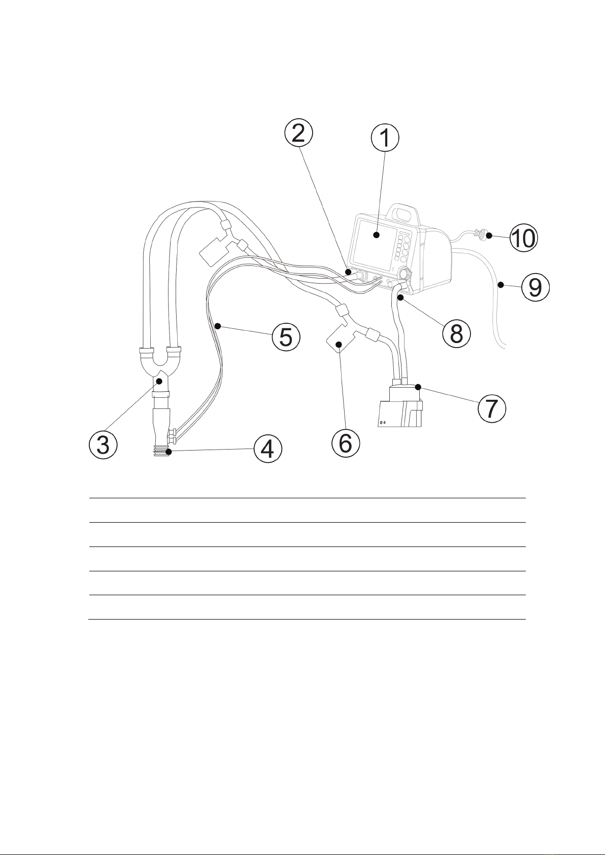
2.2.1 External pipeline connection diagram
Figure 2-1 External pipeline connection view
1. Ventilator main unit 2. Expiratory breathing tube
3. Y piece 4. Flow sensor probe
5. Flow sampling probe 6. Water trap
7. Humidifier 8. Inspiratory breathing tube
9. O2supply pipeline 10 Power cable

13
2.2.2 Front view
Figure 2-2 Front view
1. Waste gas outlet 2. Expiratory port 3. Expiratory valve rotation indication
4. Expiratory valve unlock button 5. Expiratory label 6. Nebulizer port
7. Flow sensor sampling ports
(Up: low pressure, white;
Down: high pressure, blue)
8. Speaker 9. Leak test plug
10. Inspiratory label 11. Inspiratory port 12. Knob
13. Touch screen 14. Alarm indicator 15. Button area
16. Battery indicator 17. AC power indicator
This manual suits for next models
1
Table of contents
Popular Fan manuals by other brands

TURNTIDE
TURNTIDE VES-Artex PPF AIR PPFS55 user guide

BASETech
BASETech 2330829 operating instructions

Home Decorators Collection
Home Decorators Collection 44-WWD Use and care guide

Harbor Breeze
Harbor Breeze MONTCLAIR E-CM54RBZ5CRCI installation guide

izzy
izzy IZ-9022 instruction manual

O'Fresh
O'Fresh 072 instruction manual


