wolter JFU User manual

Wolter GmbH Maschinen- und Apparatebau KG • Am Wasen 11 • D-76316 Malsch • Tel. (+49)07204/92010 • Fax. (+49)07204/920111
Wolter Asia Ltd • Unit 12, 2F • Kin Fat Industrial Centre 13 Kin Fat Street • Tuen Mun • N.T. Hong Kong • Tel. (+852)24560198 • Fax. (+852)24560290
Operation and Maintenance Manual
for
Jet Fans
JFU/JFUO/JFRO

2Operation and Maintenance Manual JF Jet Fans V 2008/10
1 General safety notes ..................................................................................................................................................3
1.1 The operator's duty of care ......................................................................................................................................3
1.2 Explanation of the safety symbols used .....................................................................................................................3
1.3 Basic safety measures ............................................................................................................................................3
1.4 Particular kinds of hazards .......................................................................................................................................4
2 Product description ....................................................................................................................................................4
2.1 Stipulated usage ....................................................................................................................................................4
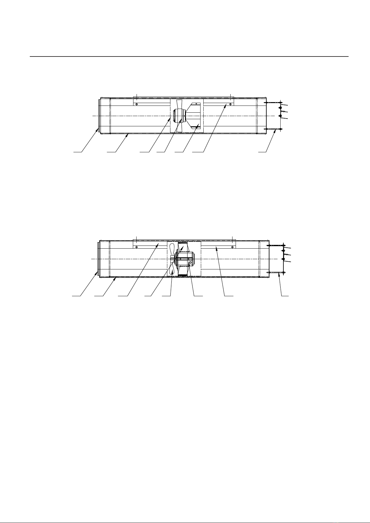
2.2 Construction ..........................................................................................................................................................5
2.2.1 JFU250/...-AE series ........................................................................................................................................5
2.2.2 JFUO/JFRO series ..........................................................................................................................................................5
2.3 Functional description..............................................................................................................................................................5
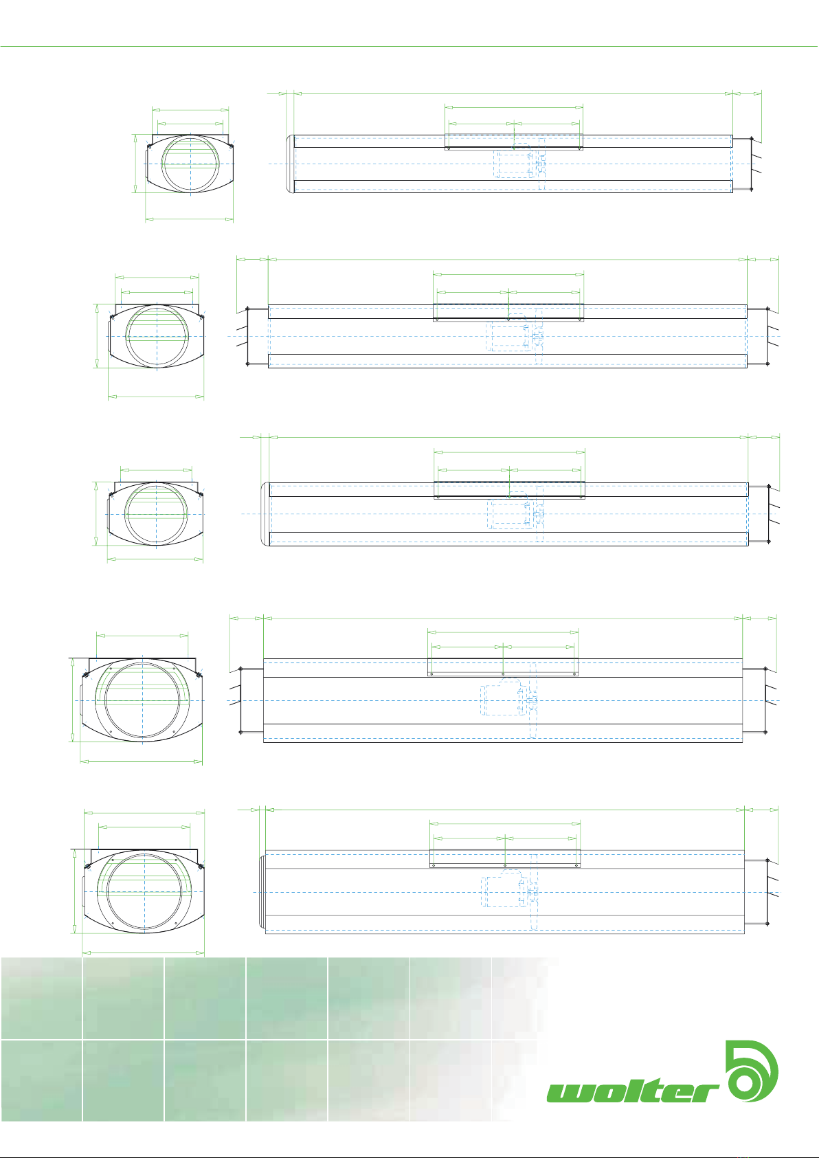
2.4 Dimensions .............................................................................................................................................................6
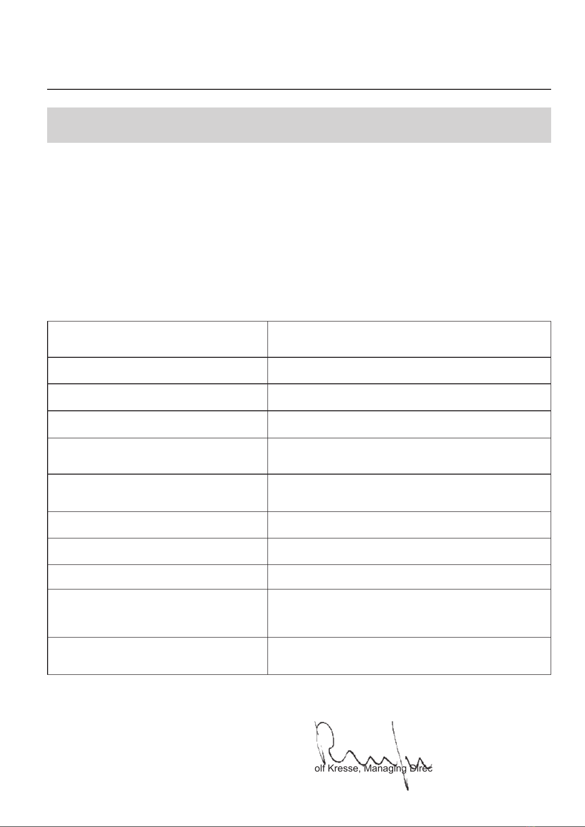
3 EC Declaration of Conformity .....................................................................................................................................7
4 Transportation and Storage .......................................................................................................................................8
4.1 Transportation ........................................................................................................................................................8
4.2 Storage .................................................................................................................................................................8
5 Assembly ...................................................................................................................................................................8
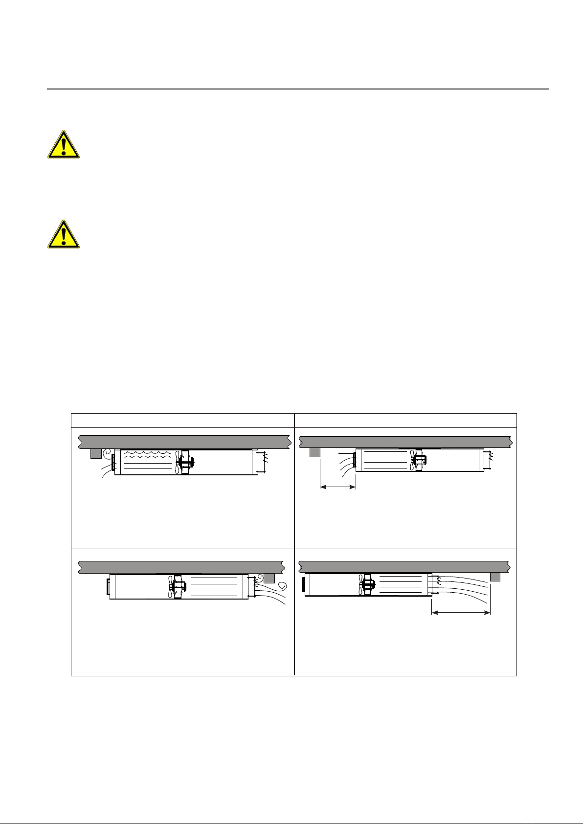
5.1 Inlet and outlet ow conditions ..................................................................................................................................9
6 Initial Start-up ..........................................................................................................................................................10
6.1 Checks prior to initial start-up .................................................................................................................................10
6.2 Starting up the fan for the rst time ..........................................................................................................................10
6.3 Checks after initial start-up .....................................................................................................................................10
7 Help with Malfunctions .............................................................................................................................................11
7.1 Tabular overview of possible malfunctions and aids in eliminating those malfunctions ...................................................11
8 Maintenance ............................................................................................................................................................12
8.1 Servicing .............................................................................................................................................................12
8.2 Overhaul .............................................................................................................................................................13
8.2.1 Removal and installation the motor-fan-assembly ..............................................................................................13
8.2.2 Dismantling the rotor ......................................................................................................................................14
8.2.3 Assembling the rotor ......................................................................................................................................14
8.2.4 Impeller blade pitch angle ...............................................................................................................................15
8.2.5 Motor bearing service intervals ........................................................................................................................15
8.2.6 Instructions on correct bearing replacement ......................................................................................................15
Contents
Table of Contents

3
V 2008/10 Operation and Maintenance Manual JF Jet Fans
1 General safety notes
1.1 The operator's duty of care
The jet fans of the JF series have been constructed and built whilst taking into account an analysis of the hazards
involved, and after careful selection of the harmonised standards to be observed, as well as other further technical
specications. They thus correspond to the current level of technology and guarantee a high degree of safety. In
operational practice, however, this level of safety can only then be attained if all required measures are taken. It is
incumbent upon the operator's duty of care to plan these measures and to monitor their execution.
In particular, the operator must ensure that
- the fan is only used as stipulated (cf. chapter, "Product Description")
- the fan is only operated in a faultless and functional condition and that safety ttings, especially, are regularly
examined with respect to their functionality
- the operating instructions are always maintained in a readable condition and are available at the fan's location
of deployment in their entirety
- only sufciently qualied and authorised personnel operate, maintain and repair the machine
- these members of personnel are familiar with the operating instructions and especially the safety notes
contained therein
- no safety and warning signs tted to the fan are removed, and that they are kept in a readable condition.
- the fan's surrounding is kept clean to avoid items from being sucked into the fan and/or blocking the air ow
1.2 Explanation of the safety symbols used
The following symbols are used in these operating instructions. These symbols are, above all, intended to draw the
reader's attention to the text contained in the adjacent safety note.
Warning
Mortal danger
Note
This symbol indicates that dangers exist which are hazardous to life and health.
Electrical hazard. Serious - and also fatal - injury can result if these notes are
disregarded.
Indicates user tips and other useful advice.
1.3 Basic safety measures
Wolter jet fans are, at the moment of delivery, manufactured to the current level of technology. Extensive materials,
function and quality checks assure them of a high level of usefulness and long service life. Nevertheless, these
machines can be dangerous if they are improperly used by untrained personnel or are used in a non-stipulated
manner.
Read these operating instructions carefully before putting the jet fans into operation!
General safety notes

4Operation and Maintenance Manual JF Jet Fans V 2008/10
Only operate the fan in its enclosed state with properly tted guide vanes and protective screens.
1.4 Particular kinds of hazards
The jet fans of the JF series are axial fans. In this respect, particular hazards are caused by the rotor and through
the ow of air, which can, at times, be considerable. For this reason the following points are to be observed:
-Never reach into the rotor when it is rotating. Do not try to use your hand as a brake for the rotor during
maintenance work.
- Loose clothing or light parts can be sucked in by the draught of air. That is why you should always wear
tight-tting clothing during maintenance work and whilst near the fan inlet.
-Larger items can obstruct or totally ruin the rotor and other parts of the fan. For this reason, the guide vanes (on
all JF jet fans) and protective screens (on JFUO jet fans) on the fan inlet and outlet must be tted at all times
during operation.
The motor-fan-assembly must not be put into operation while it is removed from the sound attenuator housing.
- Assembly, electrical connection and maintenance may only be carried out by trained craftsmen!
- Only operate the fan in the manner stipulated and within the specied output limits (see rating plate) and
with approved conveyed media!
2 Product description
2.1 Stipulated usage
Our jet fans have been specially developed for use in modern car park ventilation systems. The rotors are statically
and dynamically balanced at the factory, and manufacture is subject to the strictest intermediate and end checks
and is certied in accordance with DIN/EN/ISO 9001.
Conditions of use
The air should correspond to tender specications, as the corresponding components are determined for this. If
these are not listed in more detail, then the following applies:
The jet fans of the JF series are suitable for the conveyance of
-clean air
-air containing car exhaust emissions
-air which has little dust and grease content
-gases and vapours which are non-explosive and only slightly aggressive in nature
-media up to a maximum air density of 1.3 kg/m3
-ow volumes at temperatures ranging from - 30ºC to +40ºC (except 300ºC/1 h temperature rated fans during
emergency smoke exhaust operation)
-media up to a max. humidity of 95%
Conditions of tting
The fans are not designated for any types of usage other than those cited here, and any such use shall be
considered as improper usage!
In particular, we especially draw your attention to the following points. Non-compliance can either result in
considerable material damage or personal injury, or that the demanded fan output values are not attained.
General safety notes
The fan may not be operated without the necessary safety ttings. For this reason, the guide vanes (on all JF jet
fans) and protective screens (on JFUO/JFUjet fans) on the fan inlet and outlet must be tted at all times during
operation in order to prevent access to rotating parts.
In order to avoid any damage to the fan and specially to the rotor blades, you must prevent the possibility of
loose parts being sucked in by the fan or of other items being able to nd their way into the fan.
The tting notes regarding inlet and outlet ow conditions are to be observed (see 5.1.1).

5
V 2008/10 Operation and Maintenance Manual JF Jet Fans
2.2 Construction
1 2 3 4 5 67
The jet fan consists of the following main parts:
(1) Inlet protective screen
(2) Sound attenuating housing
(3) Motor-fan-assembly unit (removeable type)
(4) Rotor motor with welded impeller
(5) Motor support
(6) Ceiling mounting brackets
(7) Guide vane
2.3 Functional description
The jet fan is designed for installation on the ceiling of over- and underground car parks with free-suction and free-
blowing operating condition. It draws air from the surrounding on the suction side through the rotating impeller
and conveys this air in axial direction to the outlet side. This high-velocity airstream induces a secondary airow
downstream of the fan outlet and is used to mix and convey the air and the contained car exhaust emissions in the
car park. In normal applications, the jet fan is not a stand-alone product, but part of a complete jet fan ventilation
system including other jet fans, sensors, control equipment, and main exhaust and/or supply fans.
If the jet fan has been supplied as a temperature rated execution (Model designation JF .. - ... - ... - .. - .. -300°), it
may also be used to convey smoke for emergency smoke extract applications and will withstand temperatures of up
to 300°C for a duration of up to 1 hour.
The motor is positioned in the air ow and is cooled by the ow.
Control and regulation of the jet fan is carried out by an external control unit. This does not form part of the jet fan
itself. The corresponding operating instructions are to be consulted with regard to the control unit's operation.
Product description
2.2.1 JFU /...-AE series
1 2 3 4 5 678
The jet fan consists of the following main parts:
(1) Inlet protective screen (JFUO) or guide vane (JFRO, see (8))
(2) Sound attenuating housing
(3) Bar for removal of motor-fan-assembly (L type only)
(4) Motor-fan-assembly designed as slide-in tube
(5) Fan impeller
(6) Electric motor
(7) Ceiling mounting brackets
(8) Guide vane
2.2.2 JFUO/JFRO series

JFUO 250• •–Jet Fan Uni-Directional Oval Size 250
JFRO 250Jet Fan Fully Reversible Oval Size 250
JFUO 315-355-370 –Jet Fan Uni-Directional Oval Size 315-355-370
JFRO 315-355-370• •–Jet Fan Fully Reversible Oval Size 315-355-370
Dimensions
JFU180-200- 250-Jet Fan Uni-Directional Oval Size from180-200-250
1230
(L) / 1230(S)
(L) / 1230(S)
(L) / 1230(S)
(L) / 1230(S)
300 300
380
340
530
JFUO 250 -Jet Fan Uni-Directional Oval Size 250
530
400
450
352
400
352
290
340
275
1220
1220
2250
12202250
12202250
12202250
JFUO 250-300 - Jet Fan Uni-Directional Oval Size 250-300
JFUO 315-355-370 - Jet Fan Uni-Directional Oval Size 315-355-370
JFRO 370 - Jet Fan Fully Reversible Oval Size 370
JFRO 300 - Jet Fan Fully Reversible Oval Size 300
JFU 180-200-250AE - Jet Fan Uni-Directional Oval Size 180-200-250
2.4 Dimensions

7
V 2008/10 Operation and Maintenance Manual JF Jet Fans
EC Declaration of Conformity
3 EC Declaration of Conformity
In accordance with Appendix II A of the EC Machinery Directive (89/392/EWG)
DIN EN 60335-2-2 Safety of electrical equipment for household use and similar
purposes; Part 2: Special requirements for dust and water
suction machinery.
DIN EN 60335-2-80 Safety of electrical equipment for household use and similar
purposes; Part 2: Special requirements for fans.
DIN VDE 0700-220 Safety of electrical equipment for household use and similar
purposes; Fans and associated control units for use on ships
DIN EN 1037 Machine safety; Avoiding the unexpected start up of the
machinery.
DIN EN 1088 Machine safety; Locking systems in combination with
detachable protective ttings; Guiding principles for layout and
selection.
DIN EN 25136 Acoustics; Determining the irradiated noise output of fans in
ducting. Ducting behaviour (ISO 5136:1990 and Technical
Corrigendum 1:1993)
DIN EN 292-1 Machine safety; Basic terms, general guiding principles of lay-
out; Part 1: Basic terminology, methodology.
DIN EN 294 Machine safety; Safety distances for the prevention of upper
limbs coming into the vicinity of danger areas.
DIN EN 811 Machine safety; Safety distances for the prevention of lower
limbs coming into the vicinity of danger areas.
DIN EN ISO 11200 Acoustics; Noise irradiation of machines and appliances;
Guidelines on the application of basic standards for establishing
noise emission levels at the workplace and at other xed
locations (ISO 11200:1995)
DIN EN ISO 5801:1997 Performance tested to ISO5801:1997 (Airside performance)
and equal to BS848-10:1999 Fans for general purposes -
Performance testing of Jet Fans
Any changes in construction which have an effect on the technical data specified in the operating
instructions and on the machinery's stipulated usage, l.e, those changes which essentially change the
machine, shall invalidate t is declaratio of conformity!
Malsch, 04.10.2007
Hans Rudolf Kresse, Managing Director
The manufacturer: Wolter GmbH
Maschinen- und Apparatebau KG
Am Wasen 11
D-76316 Malsch
Hereby declares that the machine described
in the following:
Meets the health and safety requirements of
the following EC Directives:
In accordance with Machinery Directive (98/37/EG),
Appendix II A
in accordance with the Low Voltage Directive
(73/23/EWG)
Car park Jet Fan
Harmonised standards applied:

8Operation and Maintenance Manual JF Jet Fans V 2008/10
4 Transportation and Storage
Transportation and Storage
4.1 Transportation
Wolter fans are packed at the factory to suit the respectively agreed mode of transportation.
Transport the fan in its original packaging.
- Only use suitable means of transport, such as pallet trucks or fork-lift trucks.
- If the fan is to be transported by hand, ensure that supporting and carrying loads are kept within reasonable
limits for the personnel involved.
The following special hazards must be taken into account when transporting the equipment:
- The transportation packaging does not prevent damage to the equipment through improper transportation.
- The fans must not be dropped or thrown.
- Sharp, protruding edges can lead to injury through cuts.
-Suspended loads can fall, which then constitutes a fatal hazard - stand well clear of suspended
loads!
- Parts which have been stacked too high can collapse.
- If load-carrying devices other than those specied here are used, then this can lead to serious damage to the
machine.
- A risk of re exists due to the easily ammable nature of the packaging materials
- Do not use naked ames and do not smoke!
- Read the chapter, "General Safety Notes".
- Store the fan in a dry, weather-protected location in its original packaging or protect it from the effects of dirt
and the weather until nal assembly. Cover open pallets with tarpaulin sheets and protect the fans from the
effects of dirt and contaminants (e.g. swart, stones, wire etc.)
- Avoid extremes of cold and heat.
- Avoid lengthy storage periods (a maximum of one year is recommended) and check that the motor bearing
assembly is in good functional order prior to tting.
4.2 Storage
5 Assembly
Assembly and electrical work is only to be carried out by trained and instructed
craftsmen and in accordance with the respectively applicable regulations!
The following points are to be observed when assembling the fan:
Use only the fan's ceiling mounting brackets (see 2.2) to install the fan to the ceiling.
Use adequate mounting hardware suitable for the fan's weight.
The ceiling must be suitable to bear the weight of the fan.
The jet fan must be mounted in horizontal position.

9
V 2008/10 Operation and Maintenance Manual JF Jet Fans
When lifting the fan into its position on the ceiling during installation, secure it from falling down until it is
securely installed
Attention: Make the electrical connection in accordance with the technical connection conditions
and the relevant regulations!
Make the electrical connection as per the enclosed terminal plan in the terminal box housing
Feed in and seal the cable into the connection cabinet properly
If the motor is equipped with thermal contacts, they must be properly connected. Failure to do so will void the
warranty.
Before checking the direction of rotation:
Remove foreign bodies from the fan area.
Guide vane and inlet protective screen (see 2.2) must be tted.
Turn the rotor through a few revolutions by hand in order to test its ease of movement.
Check the direction of travel in accordance with the arrow on the housing by switching on and off very quickly.
If necessary, alter the direction of travel for 3-phase AC motors by swapping 2 phases.
In the case of single-phase motors, reverse the direction of travel by swapping Z1 with Z2 (attention: the
direction of current ow in the auxiliary winding also changes).
5.1 Inlet and outlet ow conditions
> 0.5m
On reversible fans (JFRO), both sides of the fan can act as outlet side, depending on the direction of operation.
Therefore, a minimum distance of 3 times the fan diameter to any obstacles must be observed on both sides of the
fan.
The guide vane is adjustable to change the horizontal orientation of the airow.
Assembly
Incorrect Correct
Incorrect: The jet fan's duty will be reduced if an obstacle
(e.g. ceiling beam, pipe, sign etc.) is situated too close to
the inlet. A stall condition might occur that can damage the
fan and creates additional noise.
Recommended: The distance to obstacles on the inlet
side has to be chosen according to the size of the
obstacle, but must be at least 0.5m.
Incorrect: The jet fan's duty will be reduced if an obstacle
(e.g. ceiling beam, pipe, sign etc.) is situated too close to
the outlet. A stall condition might occur that can damage
the fan and creates additional noise.
Recommended: The distance to obstacles on the outlet
side has to be chosen according to the size of the
obstacle, but must be at least 3D.
> 3D

10 Operation and Maintenance Manual JF Jet Fans V 2008/10
6 Initial Start-up
Initial Start-up
The following points are to be observed in order to avoid damage to the machinery or life-threatening injury during
initial start -up:
Only qualied personnel may carry out the machine's initial start-up and this must take place in compliance with
the safety notes.
Prior to initial start -up, check that all tools and foreign bodies have been removed from the machine.
Activate all safety devices and Emergency Stop switches prior to initial start -up.
Check the motor's direction of travel prior to initial start-up.
Read the chapter, "General Safety Notes ".
6.1 Checks prior to initial start-up
Proceed with the fan's initial start-up in the following sequence:
Check that the mechanical assembly has been carried out properly
Remove foreign bodies located in the suction and outow areas and in the fan space
Check that the electrical installation has been completed in accordance with regulations
Does the mains voltage match the motor voltage specied on the rating plate?
Is the switchgear used suitable for the motor both with respect to the switching functions to be carried out
and also to the switching conditions and switched output of the motor?
Is the motor protection system set correctly with regard to the motor's nominal current? The setting must
be carried out in accordance with the corresponding details contained on the motor output plate.
Has the motor been connected correctly in accordance with the wiring diagram?
The connection schematic supplied by the motor suppliers applies for the connection of the motor.
Accident prevention
Inlet protective screen and guide vane (JFU/JFUO) or two guide vanes (JFRO) must be tted on the inlet
and outlet of the fan to meet safety regulations.
6.2 Starting up the fan for the rst time
Only put the fan into operation after it has been assembled in accordance with the regulations!
Put the fan into operation.
Monitor its correct function (quiet running, vibration, imbalance, power consumption, controllability)
Always keep suction openings clear! Check protective screens or protective anti-intrusion ttings for dirt,
and clean if necessary!
6.3 Checks after initial start-up
Check the mechanical connections of the fan to the ceiling after initial start -up.

11
V 2008/10 Operation and Maintenance Manual JF Jet Fans
7 Help with Malfunctions
The following points must be observed in order to avoid damage to the machinery or life-threatening injury when
eliminating machine malfunctions:
- Only eliminate any malfunction if you have the specied qualications necessary for the task.
- First of all ensure that the machine cannot be switched on inadvertently, by locking the equipment's off switch
or control cabinet by means of a padlock.
- Secure the hazardous area with respect to moving machine parts.
- Read the chapter "General Safety Notes".
Help with Malfunctions
7.1 Tabular overview of possible malfunctions and aids in eliminating those
malfunctions
Symptom Cause Elimination
Motor or motor control
system switches off.
Motor too hot, thermo
contact activates.
Allow the motor to cool off. Depending upon the control
equipment in use, the fan will either start itself up or will
have to be re-started again.
Check whether:
-The conveyed medium is too hot
-All phases are evenly loaded and connected
-Operating point does not match the lay-out
-Rotor blocked
Air output incorrect Incorrect direction of travel
of the fan (JFU/JFUO)
Fan assembled incorrectly
Rotor blocked
Rotor defective
Change the direction of travel (see electrical assembly)
Either the rotor is incorrectly mounted on the motor
shaft or the whole motor-fan-assembly has been
incorrectly tted into the installation.
Switch off the fan.
Correct the incorrect assembly (rotor or motor-fan-
assembly).
Switch off the fan.
Remove the blockage. Ensure that the accident
prevention regulations are observed in the process.
Switch off the fan.
Dismantle the rotor and t a new one.
Fan is labouring
under load, air flow is
periodically interrupted
Fan is operating at an
unfavourable duty point
Make sure there are no obstacles too close to the
jetfan's inlet and outlet (see 5.1). Possibly, the impeller
interrupted blade pitch angle must be reduced(JFUO/
JFRO series only), but this alteration must be
authorized in writing by the manufacturer.
Please contact the Wolter for assistance. If this laboured
operation of the fan continues over a prolonged period,
the rotor and motor will take damage!

12 Operation and Maintenance Manual JF Jet Fans V 2008/10
8 Maintenance
Maintenance
The following safety notes must be observed when maintaining the machine - life-threatening injuries to personnel,
damage to the machine and other material damage, as well as environmental damage, will be avoided in this way.
- Cleaning, lubrication and maintenance work may only be carried out by authorised operating personnel
operating instructions are to be observed.
- Repair work may only be carried out by authorised craftsmen - accident prevention regulations are to be
observed.
- Secure the operational area over a large area prior to the commencement of maintenance work.
- The specied sequence of the working stages is to be observed exactly.
- All work on the machine's electrical equipment may only be carried out by trained electricians.
- Self-locking screws and nuts are always to be renewed.
- All specied screw torque settings are to be observed precisely.
- Read the chapter "General Safety Notes".
If the jet fan is equipped with a combined terminal box /
repair switch, it is still necessary to disconnect the mains
supply to the terminal box when performing electrical
maintenance or repairs that require opening the terminal
box!
Setting the repair switch to the "OFF" position cuts off
the power supply from the terminal box to the motor,
but the connection terminals inside the terminal box are
still energized! When unscrewing the terminal box cover,
there is a danger of contact between the cover and the
connection terminals, therefore the mains supply MUST be
disconnected to avoid the danger of electrical shock!
8.1 Servicing
The rotor and housing are subject to natural wear and tear through the action of dust, acidic and corrosive vapours,
as well as the gases which are mixed into the conveyed ow. The type and concentration of the dust, as well as the
gases and vapours, can lead to deposits, abrasion and corrossion at the rotor and housing.
The materials can be attacked by this natural wear and tear to the extent that they can no longer stand up to the
strains imposed on them. Unevenly distributed deposits on the rotor lead to an imbalanced state and thus to noisy
running, which in turn can result in damage to the impeller and motor bearing. Deposits in the housing lead to a
narrowing of the available cross-sectional area or to a roughening of the housing panels and can thus have an
unfavourable effect on the fan's output duty. Should the checks, the regularity of which depend on the conveyed
media and other operating conditions which differ in each individual case, reveal only slight wear and tear, then the
individual parts must be cleaned in good time, or replaced if necessary.

13
V 2008/10 Operation and Maintenance Manual JF Jet Fans
Prior to all servicing work:
- Bring the fan to a halt in the prescribed manner and completely isolate the fan from the mains supply!
- Wait until the rotor has come to a halt!
- Ensure that the machine cannot be switched on again!
- Clean the fan components (fan housing, inlet cone, sound attenuator tube, rotor). Do not use high-pressure
water devices for cleaning.
Only use cleaning agents generally available through the trade and in compliance with the prescribed safety
measures. Do not use scratching or scraping tools (protective surface coating will be damaged).
- If required, remove the motor-fan assembly from the sound attenuator housing
- Do not overload the motor!
- Do not bend the impeller blades
Recommended periodic inspection intervals Jet - -
- Jet fans used for CO-ventilation only: 12 months
- Jet fans used for CO-ventilation and emergency smoke ventilation: 6 months
- Jet fans used for emergency smoke ventilation only: 3 months
Periodic Inspection checks
- Check for excessive bearing play
- Check for lubricant leaking from the bearings
- Visual inspection of motor, impeller, sound attenuator housing and electric connection for damages, dirt and
dust deposits, foreign matter
- Check for unusual noises or vibration during operation
- Check tightness and security of fan suspension
8.2 Overhaul
Prior to all overhaul work:
- Bring the fan to a halt in the prescribed manner and completely isolate the fan from the mains supply!
- Wait for the rotor to come to a halt!
- Ensure that the machine cannot be switched on again!
Only use spare parts which have been tested and approved by Wolter!
8.2.1 Removal and installation the motor-fan-assembly
Removal:
- Disconnect mains supply to terminal box and set repair switch to "Off" position, if equipped.
- Open terminal box cover and disconnect motor leads on connection terminals.
- Push motor connection cable through grommets, so that it can be taken out together with the motor-fan-
assembly later.
Maintenance

14 Operation and Maintenance Manual JF Jet Fans V 2008/10
JFU- Remove four screws on the mounting foot attaching motor-fan assembly to inner sound attenuator tube
(accessible through access door in sound attenuator housing)
- Carefully pull motor-fan-assembly from inner sound attenuator tube, taking care not to damage the motor
connection cable. Secure the motor-fan-assembly from falling down when pulling it out of the casing.
Installation:
- Reverse above procedure. Make sure the motor-fan-assembly is inserted into the sound attenuator tube with
the correct orientation. After complete reassembly of the jet fan, check that the direction of airow is correct.
8.2.2 Dismantling the rotor
- Jet Fans with blade welded on rotor motor (JFU..-…-AE-..-..-...): Remove the complete unit with 4
supporting screws
Jet Fans with 150 mm hub (Model designations JF .. - ... -150- .. - .. - ... ):
Slacken off securing screw (Allen key), completely undo one grub screw and slacken off the tension cone using
the forcing drilling.
Jet Fans with 110mm hub (Model designations JF .. - ... -110- .. - .. - ... ):
Loosen central locking screw xing the impeller hub to the motor shaft. Remove washer.
- Note orientation of impeller on motor shaft for reassembly. Pull off the rotor from the motor shaft (possibly
using a puller tool).
8.2.3 Assembling the rotor
Jet Fans with blade welded on rotor motor (JF..-…-AE-..-..-...): Assembly
the complete unit with 4 supporting screws.
Push the rotor onto the motor shaft, minding the correct orientation of
the rotor on the motor shaft.
Jet Fans with 150 mm hub (Model designations JF .. - ... -150- .. - .. - ... ):
Tighten both grub screws evenly, whilst observing the torque settings given
in the adjacent table.
Jet Fans with 110 mm hub (Model designations JF .. - ... -110- .. - .. - ... ):
Put washer in place and tighten central locking screw xing impeller hub to
motor shaft.
After complete reassembly of the jet fan, check that the direction of
airow is correct.
Maintenance
Torque setting for taper hubs (jet
fans with 150mm hub)
Bushes Torque
Type Drilling Tightness
[mm] [Nm]
1008 12, 19, 24 6
1/4'' sw 3
1108 19, 24, 28
1210
1215
16, 19
24, 32 20
3/8'' sw 5
1310 14, 25, 35
1610
1615
19, 24
38, 42
- JFUO/JFU: Remove inlet protective screen.
- JFU, JFUO and JFRO of only L type will come with pullout bars
secure on mounting plate to remove casing. As per gure 1.
- Remove two screws securing the pullout bars to the side of the fan
mounting.
- JFU, JFUO and JFRO for L type, use the pullout bars for removing
the motor-fan-assembly usually from the inlet side or one end that is
usually of bigger diameter.
Remove the inlet protection screen or guide vane accordingly
JFUO and JFRO - Remove two screws attaching motor-fan assembly
to inner sound attenuator tube (accessible through access door in
sound attenuator housing) Figure 1

15
V 2008/10 Operation and Maintenance Manual JF Jet Fans
8.2.4 Impeller blade pitch angle
Jet Fans with blade welded on rotor motor (JF..-...-AE-..-..-...): this pitch angle cannot be adjustable type.
For JFUO and JFRO type, the blade pitch angle has been factory-adjusted to the optimum setting with a special
tool. Do not attempt to change this factory setting, as this is unnecessary. Doing so can result in damage to the
motor and impeller, will inuence the performance of the jet fan, and will void the warranty.
In rare cases where the jet fan is operating at an unfavourable duty point (see 7.1), please contact Wolter for
assistance.
Motor Service intervals in operating hours for
size 3000 min' 1500 min' 1000 and 750 min'
71 20000 20000 20000
80 18000 20000 20000
90 16000 20000 20000
100 14000 20000 20000
112 14000 20000 20000
Service intervals for motor bearings
8.2.5 Motor bearing service intervals
The roller bearings of the standard AC motors are
equipped with a permanently sealed lubrication system
consisting of a high-quality, temperature-resistant, roller
bearing grease. The amount of lubricant supplied to
the bearing by the motor manufacturer is sufcient for
10,000 to 20,000 operating hours. All rotor motorize
impeller (JFU…AE) is sufficient for 20,000hours
operating hours. Unfavourable operating conditions,
such as lengthy operating periods, changes in bearing
loads etc., requirethat the motor bearings are monitored
carefully. The service intervals or lubrication deadlines and amounts depend on the motor's operating conditions, the
rotary speed and size of bearing.
As only the construction size and rotary speed of the motors are usually known, the service intervals specied in
the adjacent table should be applied. They refer to a coolant temperature of 40°C in the case of horizontal tting
(construction form 83). You should consultthe manufacturer in the event that motor repairs are required within the
warranty period.
8.2.6 Instructions on correct bearing replacement
Only allow work on the electric motor to be carried out by a craftsman or by a suitable motor winding workshop.
Maintenance

16 Operation and Maintenance Manual JF Jet Fans V 2008/10
Maintenance
This manual suits for next models
2
Table of contents
Other wolter Fan manuals
Popular Fan manuals by other brands

Hearth & Home
Hearth & Home 2767/FK26 installation instructions

Kichler Lighting
Kichler Lighting Canfield Patio 310192 instruction manual

Vents
Vents VENTS TT Series user manual

ORTAL
ORTAL Power Vent System manual

Vasco
Vasco D60 User and installation manual

ELTA FANS
ELTA FANS ZOO FAN SDF Installation & maintenance

Vilpe
Vilpe ECo 200P/500 FLOW Installation, Operating and Maintenance Instruction

Unold
Unold BREEZY CLIP Instructions for use

Atlas
Atlas PERFORMANCE RIDGE installation instructions

Eglo
Eglo Whitehaven 203229A owner's manual

Becken
Becken BTF3331 instruction manual

Panasonic
Panasonic WhisperLite FV-05VQ5 installation instructions