Shenzhen Yuejiang Technology Co., Ltd Dobot M1 User manual

Shenzhen Yuejiang Technology Co., Ltd
Dobot M1 User Guide
User Guide
Issue: V1.0.4
Date: 2018-01-31

Dobot M1 User Guide
Issue V1.0.4 (2018-01-31) User Guide Copyright © Yuejiang Technology Co., Ltd
i
Copyright © ShenZhen Yuejiang Technology Co., Ltd 2018. All rights reserved.
No part of this document may be reproduced or transmitted in any form or by any means
without prior written consent of Yuejiang Technology Co., Ltd
Disclaimer
To the maximum extent permitted by applicable law, the products described (including its
hardware, software and firmware, etc.) in this document are provided AS IS, which may have flaws,
errors or faults. Yuejiang makes no warranties of any kind, express or implied, including but not
limited to, merchantability, satisfaction of quality, fitness for a particular purpose and non-
infringement of third party rights. In no event will Yuejiang be liable for any special, incidental,
consequential or indirect damages resulting from the use of our products and documents.
Before using our product, please thoroughlyread and understand the contents of this document
and related technical documents that are published online, to ensure that the robotic arm is used on
the premise of fully understanding the robotic arm and related knowledge. Please use this document
with technical guidance from professionals. Even if follow this document or any other related
instructions, Damages or losses will be happen in the using process, Dobot shall not be considered
as a guarantee regarding to all security information contained in this document.
The user has the responsibility to make sure following the relevant practical laws and
regulations of the country, in order that there is no significant danger in the use of the robotic arm.
Shenzhen Yuejiang Technology Co., Ltd
Address: 4F, A8, Tanglang IndustrialArea, Taoyuan Street, Nanshan District, Shenzhen, PRC
Website: www.dobot.cc

Dobot M1 User Guide Preface
Issue V1.0.4 (2018-01-31) User Guide Copyright © Yuejiang Technology Co., Ltd
ii
Preface
Purpose
This Document describes the functions, technical specifications, installation guide and system
commissioning of Dobot M1, making it easy for users to fully understand and use it.
IntendedAudience
This document is intended for:
Customer Engineer
Sales Engineer
Installation and Commissioning Engineer
Technical Support Engineer
Change History
Date
Change Description
2018/01/31
The first release
Add:
2.3.3 Arm Orientation
3.3.1 Installing Laser Engraving Kit
3.3.2 Installing 3D Printing Kit
3.5 (Optional) Installing soldering kit
5.2 Connecting Power Supply
5.5.6 Debugging Disabling Function
5.5.7 Debugging Homing Function
6.5 Operating Laser Engraving
6.6 Operating 3D Printing
7 Maintenance
Modify:
Update the contents about GUI according to the newest M1Studio
2.3.1 Workspace
2.4 Technical Specifications
5.4.1 Connecting Serial Port
6.1.2 Alarms Description
6.2 Operating Teaching and Playback
6.8 Operating Web Management
Symbol Conventions
The symbols that may be founded in this document are defined as follows.

Dobot M1 User Guide Preface
Issue V1.0.4 (2018-01-31) User Guide Copyright © Yuejiang Technology Co., Ltd
iii
Symbol
Description
DANGER
Indicates a hazard with a high level of risk which, if not
avoided, could result in death or serious injury
WARNING
Indicates a hazard with a medium level or low level of
risk which, if not avoided, could result in minor or
moderate injury, robotic arm damage
NOTICE
Indicates a potentially hazardous situation which, if not
avoided, can result in robotic arm damage, data loss, or
unanticipated result
NOTE
Provides additional information to emphasize or
supplement important points in the main text

Dobot M1 User Guide Contents
Issue V1.0.4 (2018-01-31) User Guide Copyright © Yuejiang Technology Co., Ltd
iv
Contents
Security Precautions................................................................................................1
1.1 General Security................................................................................................................1
Service Security................................................................................................................2
Introduction..............................................................................................................4
Overview...........................................................................................................................4
Appearance and Constitute ...............................................................................................4
Working Principle.............................................................................................................5
Workspace ...........................................................................................................5
Coordinate System...............................................................................................5
Arm Orientation...................................................................................................7
Motion Function..................................................................................................8
Technical Specifications .................................................................................................12
Technical parameters.........................................................................................12
Sizes...................................................................................................................13
Hardware Installation ...........................................................................................15
Environment Requirements ............................................................................................15
Installing the Base of Dobot M1.....................................................................................15
(Optional) Installing End Effector ..................................................................................16
Installing Laser Engraving Kit ..........................................................................16
Installing 3D Printing Kit ..................................................................................17
(Optional) Installing Air Pump .......................................................................................19
(Optional) Installing soldering kit...................................................................................21
Electrical Specifications.........................................................................................29
Interface Board ...............................................................................................................29
LED Indicators................................................................................................................29
Interface Description.......................................................................................................30
External Power Interface...................................................................................30
Body I/O Interface.............................................................................................31
External Expansion Interface.............................................................................33
Communication Interface..................................................................................36
Installation and Commissioning...........................................................................37
Installing Software..........................................................................................................37
Environment Requirements...............................................................................37
Obtaining M1Studio Software Package.............................................................37
Installing M1Studio...........................................................................................37
Verifying Installation.........................................................................................38
Troubleshooting.................................................................................................38
Connecting Power Supply...............................................................................................39
Connecting Emergency Stop Switch...............................................................................42
Connecting External Cables............................................................................................43
Connecting Serial Port.......................................................................................43
Connecting Network Cable ...............................................................................44

Dobot M1 User Guide Contents
Issue V1.0.4 (2018-01-31) User Guide Copyright © Yuejiang Technology Co., Ltd
v
System Commissioning ..................................................................................................45
Debugging Dobot M1........................................................................................45
Debugging the Power of Dobot M1 ..................................................................46
Setting IPAddress .............................................................................................47
Debugging Emergency Stop Function...............................................................50
Debugging Motion Function .............................................................................51
Debugging Disabling Function..........................................................................53
Debugging Homing Function............................................................................54
Operation................................................................................................................56
Instructions for M1Studio...............................................................................................56
Module Description...........................................................................................56
Alarms Description............................................................................................56
Saving Point in ARC Mode...............................................................................59
Saving point in JUMP Mode.............................................................................61
Operating Teaching and Playback...................................................................................61
Scripting..........................................................................................................................69
Opearting Blockly...........................................................................................................70
Operating Laser Engraving.............................................................................................72
Operating 3D Printing.....................................................................................................75
Operating I/O Assistant...................................................................................................82
Operating Web Management...........................................................................................83
Managing Offline File.......................................................................................83
UpgradingApplication ......................................................................................85
Example..........................................................................................................................87
Example of the Trajectory .................................................................................87
Example of the External Drive..........................................................................89
Example of Switching theArm Orientation at the Same Point .........................90
Maintenance ...........................................................................................................92
Routine Maintenance......................................................................................................92
Routine Inspection.............................................................................................92
Periodic Inspection............................................................................................93
Cleaning Maintenance.......................................................................................94
Maintenance of Mechanical Parts...................................................................................95
Greasing Screw Rod of Z-axis...........................................................................95
Greasing Guide Rail of Z-axis...........................................................................96
Maintenance of Electrical Parts ......................................................................................96
Replacing Encoder Battery................................................................................97
Calibration.......................................................................................................106

Dobot M1 User Guide 1Security Precautions
Issue V1.0.4 (2018-01-31) User Guide Copyright © Yuejiang Technology Co., Ltd
1
Security Precautions
This topic describes the security precautions that should be noticed when using this product.
Please read thisdocument carefully before using the robotic arm for the first time. This productneed
to be carried out in an environment meeting design specifications, you cannot remold the product
without authorization, otherwise it could lead to product failure, and even personal injury, electric
shock, fire, etc. People who use this product for system design and manufacture must be trained by
our company, relevant institution, or must have the same professional skills. The installation
personnel, operators, teaching personnel, programmers and system developers of the robotic arm
must read this document carefully and use the robotic arm strictly according to the regulations of
this document strictly.
1.1 General Security
DANGER
Robotic arm is an electrical equipment. Non-professional technicians cannot modify the
wire, otherwise it is vulnerable to injury the device or the person.
The following security rules should be followed when using the robotic arm for industrial
design and manufacture.
You should comply with local laws and regulations when operating the robotic arm. The
security precautions in this document are only supplemental to local laws and regulations.
The DANGER, WARNING, and NOTICE marks in this document are only
supplemental to the security precautions.
Please use the robotic arm in the specified environment scope. If not, exceeding the
specifications and load conditions will shorten the service life of the product even damage
the equipment.
Please ensure that the robotic arm is operated under security conditions and there is no
harmful object around the robotic arm.
The hazardous area of the robotic arm is its workspace plus 100mm. In order to prevent
people from entering the work area accidentally, it is necessary to build the safety barrier
to prohibit people from entering the hazardous area.
When the temperature is close to the freezing temperature, the other operations on the
robotic arm will not be allowed until the robotic arm moves at the rate of 10% or less for
more than ten minutes to make itself warm up.
Highly corrosive cleaning is not suited to cleaning the robotic arm. The anodized
components are not suitable for immersion cleaning.
Please execute daily inspection and regular maintenance, replace the defective parts in
time, in order to keep the equipment in working order.
Please comply with the relevant laws to deal with the product which is scrapped, and
protect the environment.

Dobot M1 User Guide 1Security Precautions
Issue V1.0.4 (2018-01-31) User Guide Copyright © Yuejiang Technology Co., Ltd
2
People cannot repair and disassemble the robotic arm without professional training. If
there is a problem with the robotic arm, please contact Dobot technical support engineer
in time.
Before operating and maintaining the robotic arm, the personnel responsible for the
installation, operation and maintenance must be trained to understand the various security
precautions and to master the correct methods of operation and maintenance.
Only trained and trained personnel may commission and set up the robotic arm.
Commissioning of the incomplete machine is prohibited until it has been installed in a
machine and the whole machine complies with the provisions of the Machinery Directive
(2006/42/EC).
The robotic arm may only be operated with the associated standard equipment. Any other
use of tools is deemed to be inaccurate use.
Only authorized personnel who are instructed in work safety must work on the machine.
Before the operation, please wear protective clothing, such as antistatic uniform,
protective gloves and protective shoes.
It is prohibited to modify or remove the nameplates, instructions, icons and marks on the
robotic arm and the related equipment.
Service Security
WARNING
It is necessary to shut off the power supply before installing the robotic arm, to prevent
any electric shock or malfunction.
The following security rules should be followed when using the robotic arm for installing,
teaching and programing.
Be careful during the robotic arm carrying or installing. Please follow the instructions on
the packing box to put down the robotic arm gently and place it correctly in direction of
arrow.
Before operating the robotic arm, please find and understand how to operate the
emergency stop function, ensure that the robotic arm can be stopped in an emergency.
You must connect the cables needed to the robotic arm first, and then power on the robotic
arm.
When operating the robotic arm over the PC, please do not enter the workspace of the
robotic arm, otherwise it will be vulnerable to injury the device or the person.
When the robotic arm is running, please do not touch the power and communication cables
at will. Before disconnecting the external equipment from the robotic arm, such as 3D
mouse, please make sure that the robotic arm is completely powered off.
When powering on robotic arm for the first time, please check Z-axis or J3 value from
M1Studio. If the value is below 10mm, an alarm about limitation is generated and
meanwhile the red indicator on the base of robotic arm is on, which is a normal

Dobot M1 User Guide 1Security Precautions
Issue V1.0.4 (2018-01-31) User Guide Copyright © Yuejiang Technology Co., Ltd
3
phenomenon. At that point, you need to click J3+ under Joint coordinate system to jog
robotic arm to the position where the J3 value is above 10mm, and then the alarm will be
cleared.
When powering on for the first time, please ensure that the emergency stop switch has
been opened (The emergency stop button is bumped). Otherwise, the robotic arm will not
work normally. If the emergency stop switch is not opened, please rotate the emergency
stop button clockwise. The emergency stop button will be bumped when rotating to 45°.

Dobot M1 User Guide 2Introduction
Issue V1.0.4 (2018-01-31) User Guide Copyright © Yuejiang Technology Co., Ltd
4
Introduction
Overview
Dobot Master 1st generation robotic arm (Dobot M1 for short) focuses on the light industrial
market with great potential, and supports teaching, playback, script control, blockly graphic
programming, laser engraving, 3D printing, vision identity and other functions, which is flexibly
used in intelligent sorting, circuit board soldering and other automatic production lines, so that it
can become the sword to solve practical problems for light industrial users, and can also become the
platform to carry the imagination of the maker. Dobot M1 has the following characteristics.
The integrated design of the driver and controller without external controller simplifies
the process of the initial installation and deployment.
The perfect calibration of servo motor, harmonic reducer and kinematic algorithm inside
Dobot M1 bring out the best of strength and speed.
The maximum load is 1.5kg, and the repeatability is 0.02mm.
Various I/O and communication interfaces are provided for secondary development.
Appearance and Constitute
Dobot M1 consists of base, Z axis, Rear Arm, Forearm and R axis. Figure 2.1 shows the
appearance.
Rear arm
Forearm R-Axis
Z-Axis
Base
Figure 2.1 The appearance of Dobot M1

Dobot M1 User Guide 2Introduction
Issue V1.0.4 (2018-01-31) User Guide Copyright © Yuejiang Technology Co., Ltd
5
Working Principle
This topic describes the workspace, principle, size, and technical specifications of Dobot M1.
Workspace
Figure 2.2 shows the workspace.
Figure 2.2 Workspace of Dobot M1
Coordinate System
Dobot M1 has two types of coordinate system, the joint one and the Cartesian one, as shown
in Figure 2.3 and Figure 2.4 respectively.
NOTE
The data shown in Figure 2.3 indicates the mechanical limitation.

Dobot M1 User Guide 2Introduction
Issue V1.0.4 (2018-01-31) User Guide Copyright © Yuejiang Technology Co., Ltd
6
Figure 2.3 Joint coordinate system
Figure 2.4 Cartesian coordinate system

Dobot M1 User Guide 2Introduction
Issue V1.0.4 (2018-01-31) User Guide Copyright © Yuejiang Technology Co., Ltd
7
Joint coordinate system: The coordinates are determined by the motion joints.
Dobot M1 contains four joints.
J1, J2, and J4 are the rotating joints, which are located and oriented in the horizontal
plane. And their axes are parallel to each other. The positive direction of these joints
is counter-clockwise.
J3 is the moving joint, which is used for the movement of the end effector in the
perpendicular plane. The positive direction of J3 is vertical upward.
Cartesian coordinate system: The coordinates are determined by the base.
The origin is the axes center of the motor of Rear Arm where Rear Arm is dropped
to the bottom of the Z-axis screw.
The direction of X-axis is perpendicular to the base forward.
The direction of Y-axis is perpendicular to the base leftward.
The direction of Z-axis is vertical upward, which is based on the right hand rule.
The R-axis is the attitude of the end center relative to the origin of the robotic arm,
of which the positive direction is counter-clockwise. The R-coordinate is the sum of
the coordinates of J1, J2 and J4.
Arm Orientation
With two types of arm orientation (lefty hand orientation and righty hand orientation),
Dobot M1 can move to nearly any position and orientation within a given work envelope. You
need to specify the arm orientation when Dobot M1 is moving. If you fail to do so, Dobot M1
may move following an unexpected path, resulting in interference with peripheral equipment.
The arm orientations are shown as Figure 2.5 and Figure 2.6.
Figure 2.5 Righty hand orientation

Dobot M1 User Guide 2Introduction
Issue V1.0.4 (2018-01-31) User Guide Copyright © Yuejiang Technology Co., Ltd
8
Figure 2.6 Lefty hand orientation
Motion Function
The motion modes of Dobot M1 include Jogging, Point to Point (PTP),ARC, and CIRCLE.
2.3.4.1 Jogging Mode
Jogging mode is the mode jogging Dobot M1 along the Cartesian coordinates or Joint
coordinates when teaching.
NOTE
This topic describes jogging mode by the GUI operation of M1Studio.
Cartesian coordinate system mode
Click X+, X- and Dobot M1 will move along X-axis in the negative or positive
direction.
Click Y+, Y- and Dobot M1 will move along Y-axis in the negative or positive
direction.
Click Z+, Z- and Dobot M1 will move along Z-axis in the negative or positive
direction.
Click R+, R- and Dobot M1 will rotate along R-axis in the negative or positive
direction.
Joint coordinate system mode
Click Joint1+, Joint1- and control Rear Arm to rotate in the negative or positive
direction.
Click Joint2+, Joint2- and control Forearm to rotate in the negative or positive
direction.
Click Joint3+, Joint3- and control Z-axis to move in the negative or positive
direction.
Click Joint4+, Joint4- and control R-axis to rotate in the negative or positive

Dobot M1 User Guide 2Introduction
Issue V1.0.4 (2018-01-31) User Guide Copyright © Yuejiang Technology Co., Ltd
9
direction.
2.3.4.2 Point to Point Mode (PTP)
PTP mode supports MOVJ, MOVL, and JUMP, which means point to point movement. The
trajectory of playback depends on the motion mode.
MOVJ: Joint movement. From pointAto point B, each joint will run from initial angle to
its target angle, regardless of the trajectory, as shown in Figure 2.7.
Figure 2.7 MOVL/MOVJ mode
MOVL: Rectilinear movement. The joints will perform a straight line trajectory from
point A to point B, as shown in Figure 2.7.
JUMP: From point A to point B, The joints will move in MOVJ mode, of which the
trajectory looks like a door, as shown in Figure 2.8.
Move up to the lifting Height (Height) in MOVJ mode.
Move up to the maximum lifting height (Limit).
Move horizontally to a point that is above B by height.
Move down to a point that is above B by height, which the height of the point
is that of point B plus Height.
Move down to Point B.
AB
①
②
③
④
⑤
▲
▶ ▶
▼
Height
Limit
Figure 2.8 JUMP mode

Dobot M1 User Guide 2Introduction
Issue V1.0.4 (2018-01-31) User Guide Copyright © Yuejiang Technology Co., Ltd
10
In JUMP mode, if the starting point or the end point is higher than or equal to Limit, or the
height that the end effector lifts upwards is higher than or equal to Limit, the trajectory is different
to that of Figure 2.8. Assuming that point A is the starting point, point B is the end point, Limit is
the maximum lifting height, and Height is the lifting height.
Point A and point B are both higher than Limit, but point A is higher than point B.
A
Limit
B
Point A and point B are both higher than Limit, but point B is higher than pointA.
ALimit
B
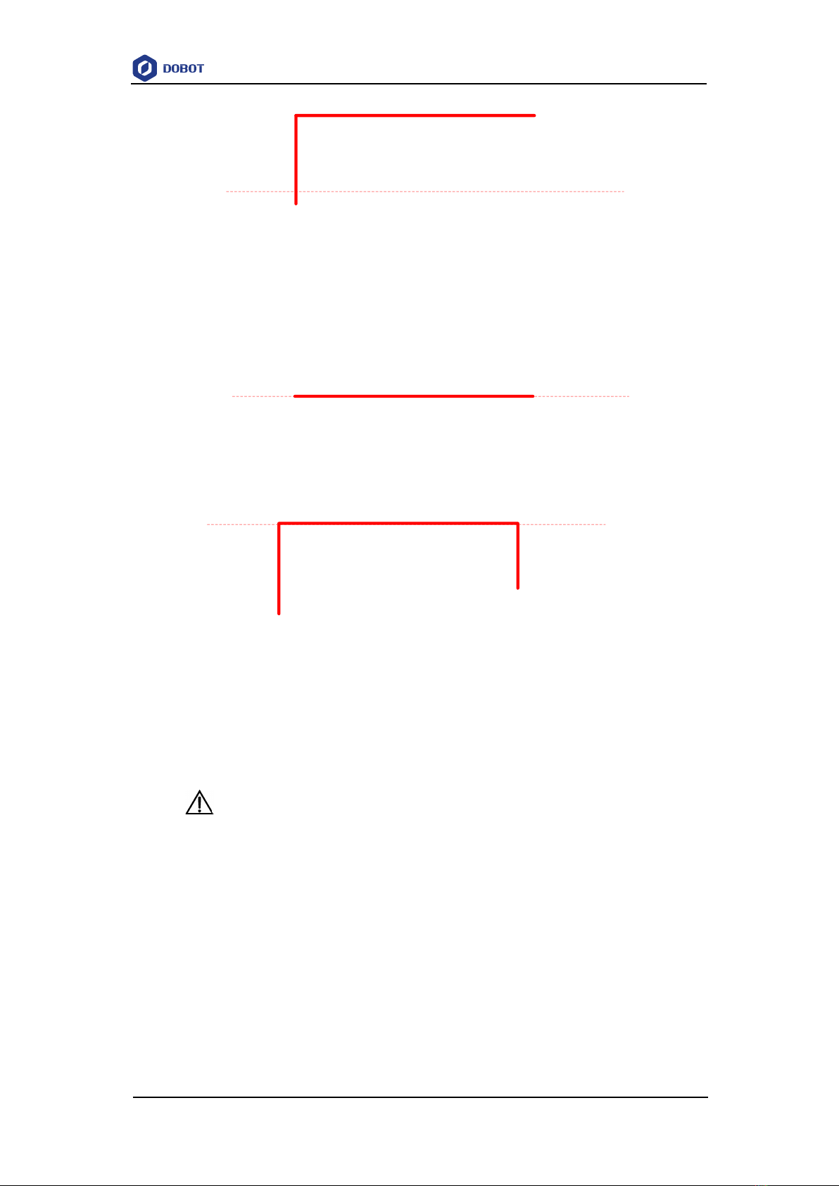
Point A is higher than Limit, but point B is lower than Limit.
A
Limit
B
The height of point A is the same as that of point B, but both are higher than Limit.
A
Limit
B
Point A is lower than Limit, but point B is higher than Limit.
Dobot M1 User Guide 2Introduction
Issue V1.0.4 (2018-01-31) User Guide Copyright © Yuejiang Technology Co., Ltd
11
A
Limit
The height of point A and point B are both the same as Limit.
ALimit
B
Point A and point B are both lower than Limit, but the height that the height of point A
plus Height and that of point B plus Height is higher than Limit.
A
Limit
B
2.3.4.3 ARC Mode (ARC)
The trajectory of ARC mode is an arc, which is determined by three points (the current point,
any point and the end point on the arc), as shown in Figure 2.9.
NOTICE
In ARC mode, it is necessary to confirm the three points with other motion modes, and
the three points cannot be in a line.

Dobot M1 User Guide 2Introduction
Issue V1.0.4 (2018-01-31) User Guide Copyright © Yuejiang Technology Co., Ltd
12
Figure 2.9 ARC mode
2.3.4.4 CIRCLE Mode (CIRCLE)
The CIRCLE mode is similar to ARC mode, of which the trajectory is a circle. In CIRCLE
mode, it is necessary to confirm the three points with other motion modes.
2.3.4.5 Application Scenarios
The application scenario depends on the trajectory in motion mode, as shown in Table 2.1.
Table 2.1 Application scenario
Motion mode
Application scenario
MOVL
If the trajectory of playback is required as a
straight line, you can choose MOVL
MOVJ
If the trajectory of playback is not required but
high speed is required, you can choose MOVJ
JUMP
If the movement of two points is required to lift
upwards by amount of height, such as sucking
up, grabbing, you can choose JUMP
ARC
If the trajectory of playback is required as an
arc, such as dispensing, you can choose ARC
CIRCLE
If the trajectory of playback is required as a
circle you can choose CIRCLE
Technical Specifications
Technical parameters
Name
Dobot M1
Reach
400mm
Payload
1.5kg
Maximum
Type
Mechanical limitation
Software limitation

Dobot M1 User Guide 2Introduction
Issue V1.0.4 (2018-01-31) User Guide Copyright © Yuejiang Technology Co., Ltd
13
magnitude
Rear arm
-90°- 90°
-85°- 85°
Forearm
-135°- 135°
-135°- 135°
Z-axis screw
0mm- 250mm
10mm- 235mm
End-effector
rotation
-360°- 360°
-360°- 60°
Maximum speed
Joint speed of
Forearm and
Rear Arm
180°/s
Resultant
speed of the
Forearm and
Rear Arm
2000mm/s
Speed of Z-
axis
1000mm/s
Repeatability
0.02mm
Power
100V-240V AC,50/60Hz
System
Linux
Communication
interface
Ethernet, RS-232C
I/O
22 digital outputs
24 digital inputs
2 DAC outputs, reserved
6 ADC inputs
Software
M1Studio
NOTE
Mechanical Limitation: Limit the position of Dobot M1 by mechanical parts.
Software Limitation: For protection, limit the position of Dobot M1 by software.
Sizes
Figure 2.10 show the size of Dobot M1.
NOTE
Z-axis Motion Range shown in Figure 2.10 indicates the mechanical limitation.

Dobot M1 User Guide 2Introduction
Issue V1.0.4 (2018-01-31) User Guide Copyright © Yuejiang Technology Co., Ltd
14
Figure 2.10 Size of Dobot M1
Table of contents


