2
CUES Inc., MPlus+ User Manual | CH905
www.cuesinc.com,| salesinfo@cuesinc.com
EQUIPMENT OVERVIEW
The standard MPlus System consists of the following equipment. Refer to the BOM and
Exploded View Drawings at the back of this manual for additional information.
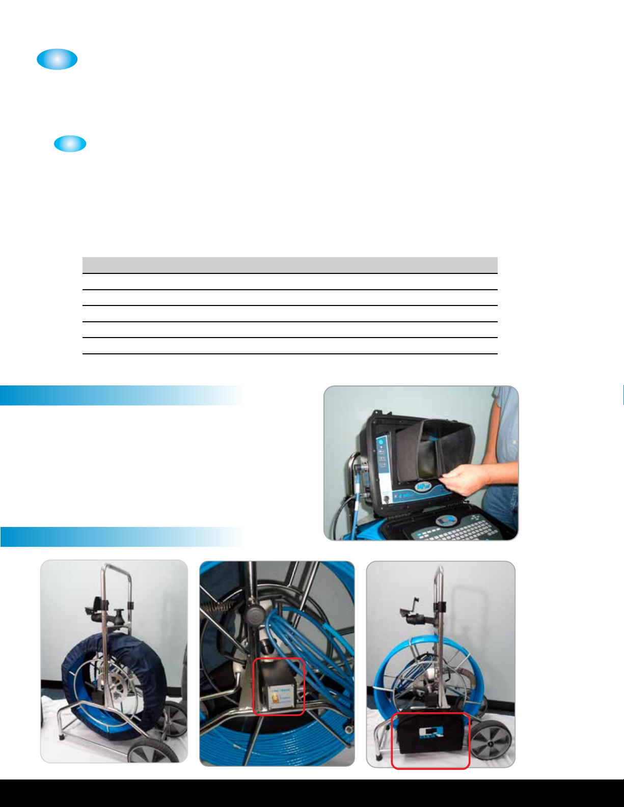
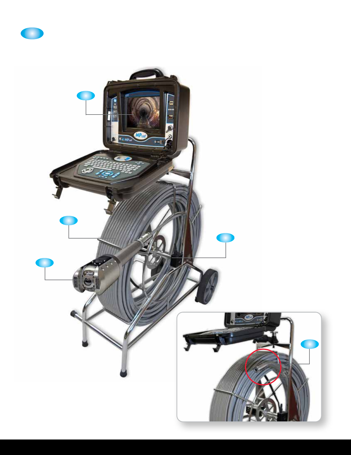
(CH) Control Unit with Text Writing, Observation Coding, Digital Recording and
Industrial Grade Monitor in an Injection Molded Enclosure:
The MPlus system is controlled by the PCU (power control unit). The PCU contains all of
the controls for the system including system power, camera, lightring, recording, video titling,
and observation coding. The following functions are included:
• .” industrial grade, optically bonded, sunlight viewable, monitor with anti-reective
properties and LED backlighting
• Operator Interface with controls for all camera functions
• Video Titling includes multiple predened and customizable screens
• Digital video recording features recording and playback of video and screenshot
picture images; Includes an internal USB ash drive with GB storage and an
external USB ash drive with GB storage for copying videos and photos
• Control Unit quick bracket mount for attaching to the coiler with hands free locking
• System Interface connector features Video, Audio, distance counter quadrature and
VDC outputs and a Video input
• Built-in Li-Ion Battery with advanced charging technology for hours of continuous use
• Universal AC power input - volt AC, / Hz, or volt DC power source
• Operation & Maintenance User Manual
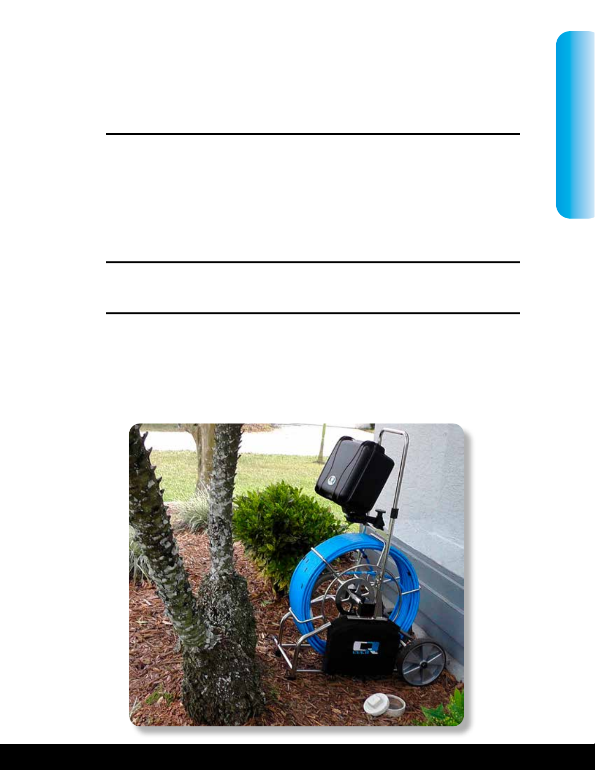
(CH) Stainless Steel Coiler:
The coiler assembly stores up to feet of .” berglass push rod and is equipped with
” wheels for easy portability.
• Heavy gauge and corrosion-resistant Stainless Steel construction
• Adjustable height handle for portability with cam locks and button stops; adjustable
from ” to ”
• Large ” durable wheels for portability and a balanced footprint for stability
• Quick-Connect allows Control Unit mounting with axes adjustability
• Adjustable coiler brake
• Integral distance sensor
(CH-PE) ’ of .” Diameter Fiberglass Rod and HDPE Jacket Push Cable:
The push cable transmits power to the self-leveling color camera and integral light ring, and
also carries the video signal back to the PCU for display on the monitor.
• Push Cable with durable HDPE jacket and advanced berglass rod
(SR SERIES) Self-Leveling Color Camera:
The mini-camera provides live video during sewer pipe inspections. It attaches to the push
cable by utilizing a exible leader spring with CX- connector.
• ½” diameter Stainless Steel camera head designed for ” to ” pipelines
• Hz integral sonde
• high intensity LED’s
STANDARD MPLUS+ SYSTEM