turned
work
pieces
of
various
diameters
present
dif-
ficulties
when
an
attempt
is
made
to
drill
through
or
into
their
centers
without
an
adequate
stabilizing
device.
The
drill
vise
or
a V
block
should
always
be
used
for
work
of
this
type.
If
the
drill
is
long
enough
to
go
through
the
piece.
but
its
'penetration
is
limited
by
the
travel
or
feed
limit
of
the
chuck.
the
piece
may
be
set
up
on
a
block
after
the
first
cut
of
maximum
feed
depth
has
been
made.
thus
allowing
the
drill
to
penetrate
to
its
max-
imum
length.
Holes
through
a'
piece.
the
thickness
of
which
is
greater
than
the
drill
length
may
often
be
completed
by
first
establishing
the
location
of
the
piece
in
rela-
tion
to
the
drill
center.
then
after
drilling
as
far
as
possible
from
one
side
the
piece
may
be
reversed
and
the
hole
completed
from
the
other
side.
All
metal
work
should
be
clamped
securely
to
the
work
table
before
drilling
is
attempted.
Should
the
drill
lodge
in
a
piece
not
clamped.
it
could
easily
tear
the
piece
from
the
operator's
grip
resulting
in
injury
to
the
operator
as
well
as
mutilation
of
the
drill
press
and
work
piece.
A
punch
mark
on
the
metal
surface
at
the
center
of
the
proposed
hole
will
tend
to
keep
the
drill
on
center
until
the
drill-spot
is
established.
Always
reduce
the
feed
pressure
when
the
drill
is
breaking
through
the
surface
of
a
work
piece.
This
reduces
the
tendency
of
the
drill
to
bite
deeply
at
this
point
and
thereby
minimizes
drill
breakage.
Avoid
set-ups
which
will
allow
the
work
to
spring.
This
will
help
minimize
drill
breakage.
Lubricants
should
be
used
on
all
metals
except
cast
iron
which
is
drilled
dry.
For
most
metals.
lard
oil is a
suitable
lubricant.
for
the
harder
metals
a
solution
of
sal
soda
in
water
may
be
used.
This
drill
press
is
designed
to
give
maximum
pro-
tection
from
moving
parts
at
all
times.
Since
a
guard
on
the
chuck
and
drill
would
also
hide
the
work.
it
must
be
impressed
upon
the
operator
that
as
with
all
rotating
power
tools.
no
loose
clothing
should
be
worn
when
working
with
the
drill
press.
The
face
should
be
kept
away
from
the
drill
so
that
the
hair
does
not
become
entangled
with
moving
parts
or
that
flying
chips
do
not
injure
the
operator.
Accessories
are
available
with
which
further
opera-
tions
may
be
performed
on
your
drill
press
such
as
dovetailing.
shaping.
routing.
carving.
sanding.
spot
finish
or
engine
turn.
cutting
of
plugs
or
dowels.
flut-
ing
and
reeding
and
buffing.
An
interesting
booklet
covering
details
on
these
various
operations
is
avail-
able.
il
II
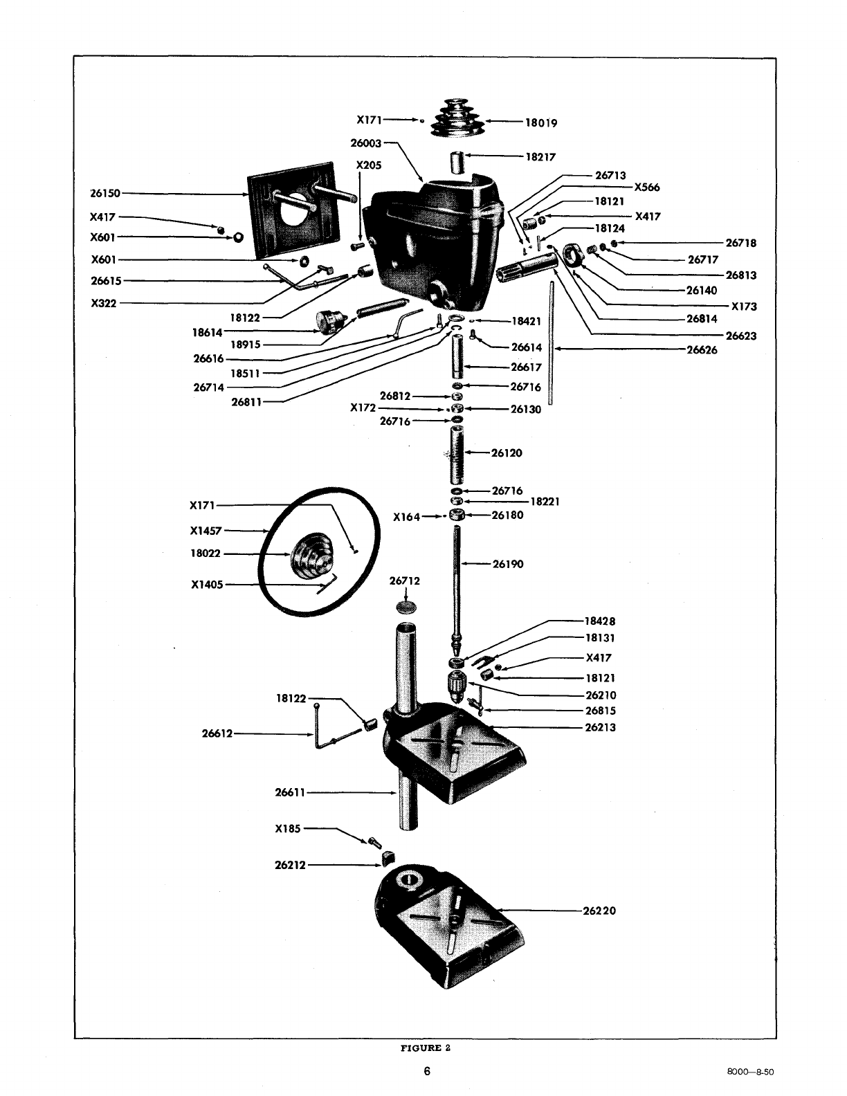
PARTS LIST
il
I
Part
No.
18019
18022
18121
18122
18124
1813 I
18217
18221
18421
18428
1851 I
18614
18915
26003
26120
26130
26140
26150
26180
26190
26210
26212
26213
NAME
OF
PART
Prepaid
Selling
Price
(Each)
Pulley
(Spindle)
........
_
...........
..
Pulley
(Motor)
............••...•.....
Headstock
and
Table
Lock
..••••••......
Headstock
and
Table
Lock
Sleeve
........•
Pin
..............................
..
Chuck
Release
Wedge
...............
,
..
Headstock
Bushing
••.•..•..•..........
Ball
Bearing
••.••.••..••..•..........
Washer
•.•..••.••.•••.•..•..••.••..•
Thrust
Collar
Nut
..•...........•......
Adj.
Knob
Lock
Screw
..••..••.•....•..•
Feed
Return
Adj.
Knob
...•........•....
Feed
Return
Spring
•.•..•...........•..
Head
Frame
Aaay
.••.••..•..•.......•.
Quill
Assy
.•.•.••••••••............••
Upper
Spindle
Collar
&
Set
Screw
.......•
Feed
Stop
Collar
&
Set
Screw
.••.........
Motor
Mount
•.....•..............•..
Spindle
Collar
and
Set
Screw
............
.
Spindle
............................•
Chuck
and
Key
.............•.........
Lock
Shoe
.•.•.•..•.......•.•..•...••
$1.80
1.70
.30
.30
· I5
.20
.40
.25
.15
.35
•I5
.65
.25
16.00
2.00
.30
.50
2.50
.35
3.75
10.00
.25
Table
. • . . . • . . . • . . . . . . . . . . . . . . • . . • .
.•
10.00
26220
Base
••••....
,........................
I 1.00
266 I I
Column...
• • • • • • . • • • • . . • . . • . . . . . . •
.•
3.00
26612
Table
Lock
Handle....................
.35
26614
26615
26616
Pinion
Retaining
Screw
•••••.••...•..••
Headstock
Lock
Handle
'"
..••••.•.••.•
Quill
Lock
Handle
•••••••••••••••..•.•
·I5
.35
.
20
Prepaid
Part
No.
NAME
OF
PART
Price
Selling
'.j
(Each)
I
26617.
-Splined
Sleeve
..•.
--~.
,
••.
~~----
•
$2.D.O..
--')11
26623
Pinion
............................
2.75 I
26626
Feed
Handle
•.••...•...•••••...••••
.50
26712
Column
Plug.......................
.15
267
I3
Pointer............
• • . . • • • . . • . • • . • • •I5
II
267
I4
Steel
Washer
•.....••..•••.•••••
,...
•I5
;!
26716
Fibre
Washer
.......................
.15 .
267 I7
Steel
Disc
.•.
. . . . • . . • . • • • • . . • • • • . • • • •I5
,"
267
I8
Leather
Disc.
. • . . . • • • . . . . • • • . . • . • • . . •
15
268
I I
Snap
Ring.
. • • • . . . • . . • . . . . . . • . • • • • • . . I 5
268
I2
Rubber
Washer
•••...••.•••••••.••.•
•I 5
268
I3
Feed
Handle
Thrust
Spring
. . . . . . . • • • . • •I5
268
I4
Feed
Handle
Snap
Ring
..............
•I 5
26815
Chuck
Key
........................•
.80
X-164
Set
Screw
No.
6-32
x
3/16
Slotted
Hd.
X-I71
X-I72
X-I73
X-I85
·X-205
·X-322
X-417
·X-566
X-601
·X-1405
X-I457
Round
Point
......................
.
Set
Screw
!4-20
x
Ys
Socket
Hd.
Cup
Pt.
Set
Screw
];4-20
x
5/16
Socket
Hd.
Cone
Point
..•.•...•.........•.•........
Set
Screw
!4-20
x
5/16
Socket
Hd.
Cup
Point
.................•..•.......•
Set
Screw
Y2-"-
I3 x
1!4
Square
Hd.
Cup
Point
..•....••........
,
........••..•
Cap
Screw
5/
16-
18
x
~
Hex
Hd
.•••.•
Mach.
Bolt
5/16-18
x 2
Sq.
Hd
...•...•
Hex
Nut
5/1
6-18
Am.
Std.
Reg.
Full
..•
Mach.
Screw
No.
6-32
x
3/1
6
Round
Hd
..
Plain
Washer
11/32
•.•.••.••••••.•..
Allen
Wrench
Vs
Std.
•
..•.••..•...•••
V-Belt.
purchase
from
your
nearest
Sears
retail
store
or
mail
order
house.
Ask
for
Catalog
No. 9- I637
•....••••..•..•.•
.10
.10
.10
.10
.10
.10
.10
.10
.10
.10
•I5
·Part.
marked
in
this
manner
may
be
purchased
locally.
This
sheet
is
intended
for
instruction
and
repair
parts
only
and
is
not
a
packing
slip.
The
parts
shown
and
listed
may
include
accessories
not
necessarily
part
of
this
tool.
All
parts
are
shipped
prepaid.
All
prices
are
subject
to
change
without
notice
.
• 5