Sherman + Reilly PLW-250-4-T Guide
Pilot Line/
Drum Puller
• Operation
• Service
• Parts
SHERMAN & REILLY, INC.
P.O. Box 11267 •400 West 33rd Street
Chattanooga, TN 37401 USA
Phone 423•756•5300
Fax No. 423•756•2948
Toll-Free 800•251•7780
Web Site www.sherman-reilly.com
© Copyright December 2, 2010 Sherman & Reilly, Inc.


I
TABLE OF CONTENTS
Section 1 • INTRODUCTION
Important Information . . . . . . . . . . . . . . . 1.1
Specifications .....................1.2
Section 2 • SAFETY
WarningTerms ....................2.1
Operator Safety Precautions . . . . . . . . . . 2.1
Employer Safety Requirements . . . . . . . . 2.3
Section 3 • OPERATION
Description of Operating Controls . . . . . 3.1
Terms You Need To Know. . . . . . . . . . . . 3.5
Pre-Operation Inspection . . . . . . . . . . . . 3.7
Towing.......................... 3.8
Reel Drive Coupling Shifter. . . . . . . . . . . 3.9
Filling the Pulling Reel . . . . . . . . . . . . . . 3.9
Emergency/Parking Brake . . . . . . . . . . . 3.10
Emergency While Pulling . . . . . . . . . . . 3.10
Payout Overspin Brake . . . . . . . . . . . . . 3.10
Pulling..........................3.11
LevelWinding....................3.14
JumpStarting.....................3.15
Section 4 • SERVICE
eneralService....................4.1
Important Information . . . . . . . . . . . . . . . 4.1
Safety Precautions . . . . . . . . . . . . . . . . . . 4.2
Hydraulic System . . . . . . . . . . . . . . . . . . 4.3
Engine...........................4.3
Service Requirements
Daily.........................4.4
Weekly .......................4.4
Semi-Annual ...................4.5
Reel and Pillow Block Bearings. . . . . . . . 4.5
PayoutBrake......................4.5
Chain and Sprocket. . . . . . . . . . . . . . . . . 4.5
Section 5 • TROUBLESHOOTING
Engine Will Not Start or Run. . . . . . . . . . 5.1
Reel Will Not Turn. . . . . . . . . . . . . . . . . . 5.1
Reel Does Not Stop When Control
Lever is Shifted To Neutral . . . . . . . . . 5.1
Front Jack Creeps Down . . . . . . . . . . . . . 5.1
Unit Will Not Build Maximum
Hydraulic System Pressure. . . . . . . . . 5.1
Hydraulic Fluid Temperature is High. . . . 5.1
Engine Electrical Schematic (Diesel) . . . . 5.2
Air Plumbing Diagram (ABS Air Brakes) . 5.3
ABS Air Brakes Wiring Diagram . . . . . . . 5.4
Trailer Wiring Diagram . . . . . . . . . . . . . . 5.5
Hydraulic Hoses & Fittings Schematic. . . 5.6
Section 6 • PARTS
Operator’s Seat & Miscellaneous. . . . . . . 6.1
Trailer Components. . . . . . . . . . . . . . . . . 6.2
Pump Assembly. . . . . . . . . . . . . . . . . . . . 6.4
Hydraulic Tank . . . . . . . . . . . . . . . . . . . . 6.5
Controls. . . . . . . . . . . . . . . . . . . . . . . . . . 6.6
Operating Controls . . . . . . . . . . . . . . . . . 6.7
Cross Relief Valve Assembly Controls . . . 6.8
Hydraulic Jack Assembly (Optional) . . . . 6.9
Engine and Components . . . . . . . . . . . . 6.10
Drive Assembly . . . . . . . . . . . . . . . . . . . 6.11
Reef Shaft Assembly . . . . . . . . . . . . . . . 6.12
Shifter/Braker Assembly. . . . . . . . . . . . . 6.13
Levelwind Assembly (Current). . . . . . . . 6.14
Miscellaneous . . . . . . . . . . . . . . . . . . . . 6.16
Trailer Lighting . . . . . . . . . . . . . . . . . . . 6.17
Axle............................6.18
Wheel Hub Assembly . . . . . . . . . . . . . . 6.19
Air Brake Assembly . . . . . . . . . . . . . . . . 6.20
Shifter/Brake Asesmbly (Older Models) . 6.21
Levelwind Assembly (Older Models). . . 6.22
Reel Shaft Assembly (Older Models) . . . 6.24
December 2, 2010

II
TABLE OF CONTENTS
1.1
Section 1 • INTRODUCTION
IMPORTANT INFORMATION
It is very important to all of us at Sherman &
Reilly that every machine is operated in a safe
manner. We have taken every precaution to
guard against the possibility of an accident. To
properly, safely operate this machine, it is neces-
sary and important that operators and service
people read and understand the information in
this and the engine manufacturer’s manual.
ANYONE working around the machine should
read the safety precautions in the manuals. Be
aware each warning and precaution is to help
protect against needless injury. Taking unneces-
sary risks and ignoring warnings is the primary
cause of personal injury and fatal accidents in
the work place. If you have any questions regard-
ing operation or safety of a procedure or situa-
tion, contact the Sherman & Reilly Customer
Service Manager at 1-800-251-7780.
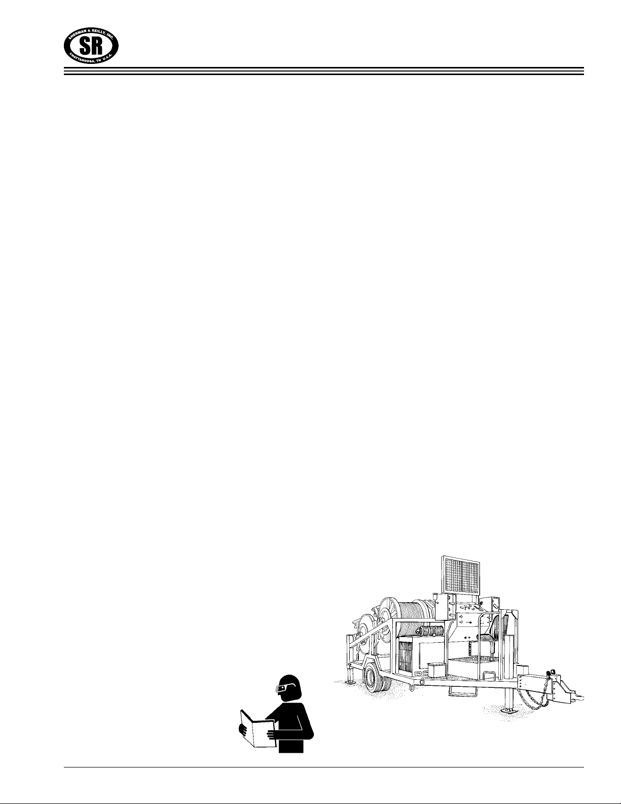
The Sherman & Reilly Model PLW-250/300 Pilot
Line/Drum Puller is a gas or diesel engine pow-
ered, hydraulically operated trailer or skid
mounted machine. It is designed to pull one, two
three or four conductors simultaneously. Each
reel has infinitely variable speed and line tension
control. This manual was prepared to help the
operator use and service the machine in a safe
manner. Responsibility for safety during opera-
tion and service rests with the person(s) doing the
work. Be alert, observe, and practice all safety
measures, including OSHA requirements and
ANSI standards, to help prevent the possibility of
an accident.
This manual is of no value if the operator does
not read and understand the instructions and
precautions (before starting and trying to operate
the machine). The operator must be
aware of the machine’s capacities
and limitations. It is the operator’s
responsibility to watch for
situations and conditions which
could affect the normal
performance of the machine and safety in the
work area.
Publication of this manual and the safety pre-
cautions in it does not in any way represent an
all inclusive list. It is the operator’s responsibility
to make sure the machine is operated in accor-
dance with all state and local safety require-
ments and codes, including all applicable OSHA
(Occupational Safety and Health Act) and ANSI
(American National Standards Institute) regulations.
Should a problem or unsafe condition arise,
shut the machine down using the normal shut-
down procedure. In the event of an emergency,
use the emergency stop procedure. Turn igni-
tion key off, then apply emergency/parking
brake. Notify the proper authority or follow your
employer’s prescribed procedure for an emer-
gency situation.
Sherman & Reilly strongly recommends that only
persons literate and understanding the English lan-
guage be considered as operators or service per-
sonnel for the Sherman & Reilly Model PLW-
250/300 Pilot Line/Drum Puller.

1.2
Section 1 • INTRODUCTION
GENERAL SPECIFICATIONS MODEL PLW-250-4-T DRUM PULLER*
Maximum Pulling Capacity (each reel). . . . . . . . . . . . . . . 48,500 In. Lbs. of Torque (2,500 lbs. on Top of Reel
MaximumSpeed ....................................................4MPH(Avg.toFillReel)
Reel Capacity . . . . . . . . . . . . . . . . . . . . . . . Rope Diameter .5" – 11,000 Ft.; Rope Diameter .625" – 7,000 Ft.
Engine ............................................................KubotaDiesel(Standard)
DriveSystem...................................................Hydraulic/ChainandSprocket
Hydraulic System Oil . . . . . . . . . . . . . . . . . . . . . . . . . . . . . . . . . . . . . . . . . Dexron Quality Transmission Fluid
HydraulicReservoir ......................................................35 allonCapacity
Emergency/Parking Brake . . . . . . . . . . . . . . . . . . . . . . . . . . . . . . . Spring Applied/Hydraulic Pressure Released
Payout (Overspin) Brake . . . . . . . . . . . . . . . . . . . . . . . . . . . . . . . . . . . . . . . . . . . . . . . Caliper/Disc (Hydraulic)
LevelWind.......................................................FourHydraulic(1perReel)
Construction........................................................RectangularSteelTubing
Reel . . . . . . . . . . . . . . . . . . . . . . . . . . . . . . . . . . . . . . . . . . . . . 38.5" Flange x 12.75" Core x 29" Inside Width
Net Weight (without rope) . . . . . . . . . . . . . . . . . . . . . . . . . . . . . . . . . . . . . . . . . . . . Approximately 10,250 lbs.
OverallLength .....................................................Approximately17ft.8in.
OverallWidth...........................................................Approximately8ft.
Height to Top of Control Panel (guard down) . . . . . . . . . . . . . . . . . . . . . . . . . . . . . . . Approximately 7 ft. 6 in.
Maximum ross Vehicle Weight Rating . . . . . . . . . . . . . . . . . . . . . . . . . . . . . . . . . . . . . . . . . . . . . 16,000 lbs.
Axle.............................................................................Single
Suspension.....................................................................LeafType
Tires...............................................................8.25x15Dual(14Ply)
TrailerBrakes.....................................................................Electric
FuelCapacity ..................................................................27 allon
ElectricSystem....................................................................12Volt
Jacks . . . . . . . . . . . . . . . . . . . . . . . . . . . . . . . . . . . . . . . . . . . . . . . . . Front: Hydraulic; Rear: Drop Leg and Pin
Towing...............................................................AdjustablePintleEye
SafetyChains/Hooks..................................................................Two
Lights(Tail,Turn,Stop,andClearance)..................................................12Volt
Paint...............................................................SafetyOrangeStandard
GENERAL SPECIFICATIONS MODEL PLW-300-T PILOT LINE WINDER*
Maximum Pulling Capacity (each reel). . . . . . . . . . . . . . . 60,000 In. Lbs. of Torque (3,000 lbs. on Top of Reel
MaximumSpeed...................................................3.5MPH(Avg.toFillReel)
Reel Capacity . . . . . . . . . . . . . . . . . . . . . . . Rope Diameter .5" – 11,000 Ft.; Rope Diameter .625" – 7,000 Ft.
Engine...........................................................................Diesel
DriveSystem...................................................Hydraulic/ChainandSprocket
Emergency/Parking Brake . . . . . . . . . . . . . . . . . . . . . . . . . . . . . . . Spring Applied/Hydraulic Pressure Released
LevelWind.......................................................FourHydraulic(1perReel)
Net Weight (without rope) . . . . . . . . . . . . . . . . . . . . . . . . . . . . . . . . . . . . . . . . . . . . Approximately 12,390 lbs.
OverallLength .........................................................Approximately19ft.
OverallWidth..........................................................Approximately 8ft.
Height to Top of Control Panel (guard down) . . . . . . . . . . . . . . . . . . . . . . . . . . . . . . . Approximately 7 ft. 6 in.
rossVehicleWeightRating......................................................16,700lbs.
rossAxleWeightRating ........................................................15,500lbs.
Suspension.....................................................................LeafType
Tires.................................................................Dual215/75R17.5-H
Trailer Brakes. . . . . . . . . . . . . . . . . . . . . . . . . . . . . . . . . . 12.25x5, Electric Brake; Optional 12.25x5 Air Brake
Jacks.................................................Front:Hydraulic;Rear:DropLegandPin
SafetyChains/Hooks..................................................................Two
Towing...............................................................AdjustablePintleEye
Lights(Tail,Turn,Stop,andClearance)................................................Standard
Paint...............................................................SafetyOrangeStandard
* Dimensions, weights, capacities are approximate. Manufacturer’s specifications subject to change without notice.
2.1
Section 2 • SAFETY
WARNING TERMS
Signal words in this manual call the operator’s
attention to safety concerns.
The word DANGER indicates the information
relates to a specific immediate hazard which, if
disregarded, will result in severe personal injury
or death.
The word WARNING indicates the information
relates to a specific immediate hazard or unsafe
practice which, if disregarded, could result in
personal injury or death.
The word CAUTION indicates the information
pertains to a potential hazard or unsafe practice
which, if disregarded, may result in minor per-
sonal injury or equipment damage.
The word NOTE indicates the information is
important to the correct operation or mainte-
nance of the machine.
DANGER
WARNING
CAUTION
NOTE
Do not place any part of the body into a poten-
tial pinch point. The machine must be turned
off and locked out in accordance with OSHA
re ulations before attemptin to correct a prob-
lem, workin on the machine, or performin
re ularly scheduled service.
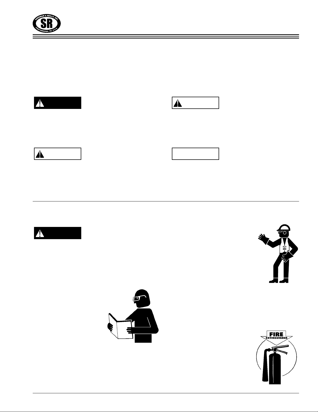
Do not attempt to operate
Sherman & Reilly
equipment without
proper instruction,
including reading and
understanding the manual.
Obey and enforce all warnings including OSHA
requirements and ANSI standards.
Never allow anyone to ride on the unit while it is
being towed.
Always wear proper safety equip-
ment as required by employer.
Never bypass safety switches or
operate equipment with faulty
safety devices.
Be sure all guards and access
covers are secure in place when the machine is
being operated.
Be aware of people in the work area who may be
at risk during operation.
Know all emergency
shutdown procedures.
Do not obstruct controls or
fire extinguisher.
Make sure fire extinguisher
is fully charged.
DANGER
OPERATOR SAFETY PRECAUTIONS

2.2
Section 2 • SAFETY
Never operate equipment while under the influ-
ence of any substance which could impair oper-
ator ability or judgement. This presents a safety
hazard in the work place.
Always use employer approved grounding pro-
cedures when operating the machine.
Do not operate equipment if work ability is
impaired by fatigue, illness, or other causes.
Never operate machine with engine cover
removed.
Never use hands to check for hydraulic system
leaks. Hydraulic fluid escaping under pressure
can cause personal injury.
Avoid contact with pumps, cylinders, hoses,
engine components, and exhaust system.
Do not refuel unit while the engine is running or
hot.
Do not jump start with cable ground connection
directly on the battery.
Keep all body parts, head, and limbs away from
all moving parts.
Refer to the engine manufacturers’ manual for all
safety precautions which relate to engine opera-
tion and service.
Know location and function of all controls,
gauges, instruments, and protective devices.
Never use unit to tow or winch another vehicle.
Never use controls or hoses for hand holds.
Do not climb on machine – use the operation
platform.
Do not exceed unit
specifications and
limitations for weight.
Know where to get help
in the event of an
emergency or injury.
Maximum towing speed is 60 miles per hour for
the PLW-250/300 Pilot Line/Drum Puller Towing
speed may be slower in certain conditions.
Do not make physical contact with rope or cable
as it enters or leaves machine or reel.
To prevent the possibility of electrocution, do
not enter or leave the unit while it is operating
or allow anyone to touch or lean on the
machine when in use.
2.3
Section 2 • SAFETY
This guideline is intended to assist owners/
employers to ensure equipment is serviced and
operated in a safe manner. Each job site may
have additional situations and conditions which
need consideration.
Monitor the operators to be sure they observe
and practice safety procedures and operate the
support equipment as outlined in this manual.
Establish a regular inspection program which
includes malfunction reports, inspection, and
service records. This inspection should cover the
machine condition, adjustment, and ensure all
safeguards are in place and functional.
Make sure that any malfunction or breakdown
that will affect the safe operation of the equip-
ment is properly corrected or repaired before
returning machine to service.
The employer shall provide training and instruc-
tion in safe methods of work before assigning
workers to operate, service, or repair the equip-
ment. A record of training dates, employee
names, and level of training should be main-
tained. Only persons literate and understanding
the English language should be considered to
operate the PLW-250/300.
Employer shall utilize a lock-out/tag-out proce-
dure which complies with part 1910.147 of Title
29 of the Code of Federal Regulations (OSHA).
The procedure will include control of all keys.
The employer will specifically inspect all safety
equipment and protective devices on the equip-
ment to ensure they are not bypassed or dis-
abled. Operation of the equipment will not be
permitted unless all safety devices are functional
and in place. The employer shall meet the appro-
priate protection requirements for the workers.
EMPLOYER SAFETY REQUIREMENTS

2.4
Section 2 • SAFETY

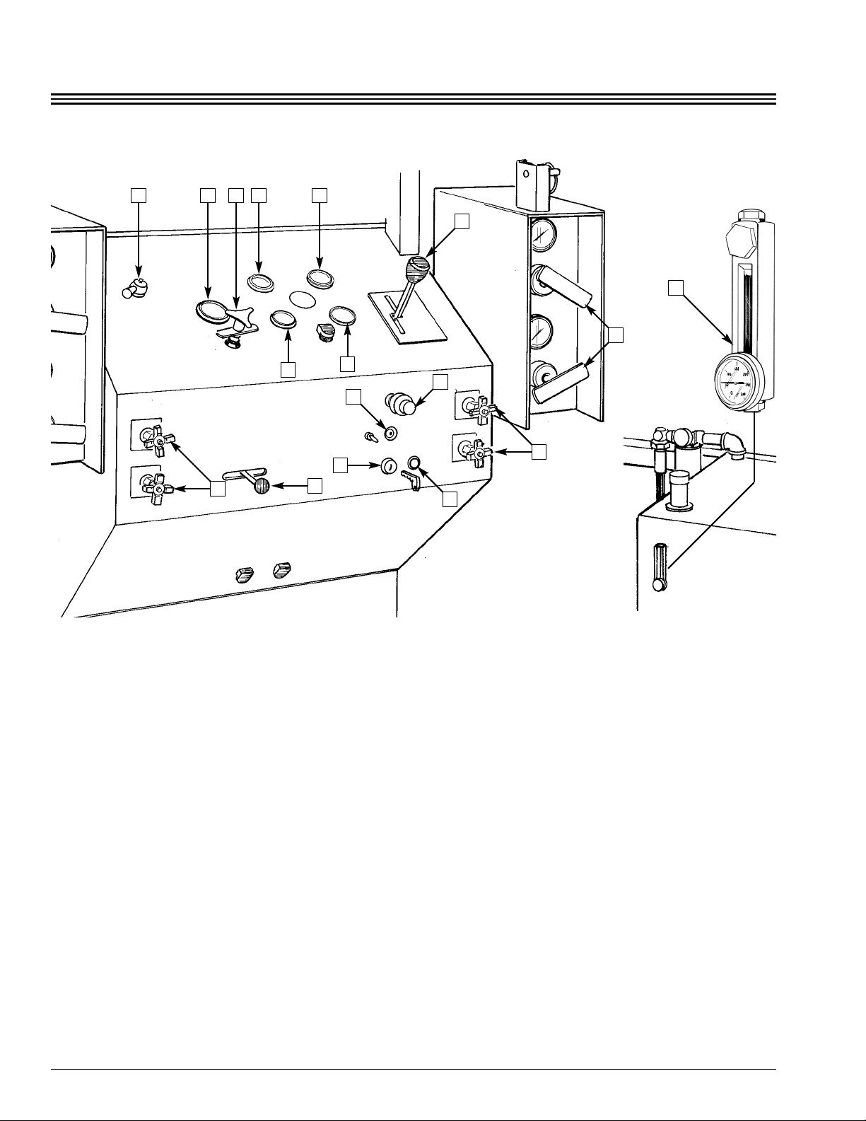
1) Emergency Parking Brake
This two-position control is used to stop the reel
in an emergency situation and for holding the
reel when necessary. The brake must be released
or “off” for the reel to operate. The brake is spring
applied and hydraulic pressure released. The
brake engages automatically when hydraulic
pressure is lost. Parking brake should be applied
when operations have stopped.
Emer ency brake does not function when drive
clutch is disen a ed (each reel has a drive clutch).
2) Glow Lamp
This lamp indicates the preheat level of the glow
plugs.
3) Drive System Pressure Gauge
This 0 to 3000 PSI variable control gauge indi-
cates the existing hydraulic system pressure set-
ting.
4) System Pressure Control (Decrease/Increase
This variable-position control increases and
decreases the hydraulic motor torque. This con-
trol determines how much tension is on the line.
Clockwise rotation increases hydraulic pressure.
Counter-clockwise rotation decreases pressure.
Always leave pressure control knob approxi-
mately three inches counter-clockwise (left) from
panel when the machine is not in use.
CAUTION
3.1
Section 3 • OPERATION
DESCRIPTION OF OPERATING CONTROLS
8
1 3 4 14 13
11 12
5
8
7
10
16
15
76
2
3.2
Section 3 • OPERATION
5) Reel Speed and Direction Control
This control lever determines the direction the
reel will rotate and at what speed from slow to
maximum speed. The farther the lever is moved
from neutral position, the faster the reel turns.
6) Level Wind Control Left/Right/Neutral
This three position lever controls the side move-
ment of the telescoping hydraulic level wind. The
control returns to neutral and movement stops
when the lever is released.
7) Level Wind Speed Control
(Increase/Decrease)
There are four control knobs, one for each Reel/
Level Wind. Each level wind movement speed
is individually set with the specified control.
Turn knobs counter-clockwise (left) to increase
speed and clockwise (right) to decrease speed.
8) Payout Brake Control (Decrease/Increase)
There are four control handles with gauges. Each
reel payout brake can be individually set to the
amount of tension or drag desired. The gauge
indicates the brake pressure in pounds per
square inch (PSI). Rotate handle counter-clock-
wise (left) to decrease pressure/drag and clock-
wise (right) to increase pressure/drag.
9) Hydraulic Oil Level/Temperature Gauge
This gauge displays the fluid level of the
hydraulic tank. It also has a temperature gauge to
indicate oil temperature.
10) Throttle Control
The throttle control is used to set the engine
speed. The red release button must be pushed to
move the control. Pull out to increase speed,
push in to decrease speed.
1 3 4 14 13
11 12
5
8
7
10
16
15
76
2
9
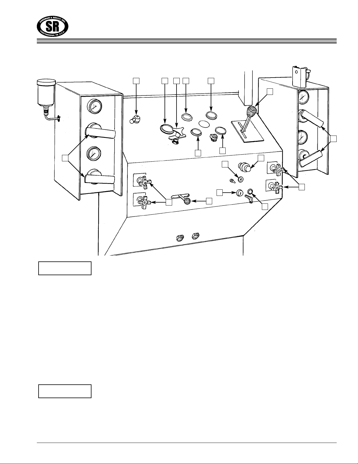
3.3
Section 3 • OPERATION
This is a fine speed adjustment knob. Rotate
clockwise to decrease en ine speed, counter-
clockwise to increase en ine speed.
*Fuel Gauge
This gauge displays the amount of fuel remaining
in the fuel tank (on fuel tank).
*Emergency Cut-Out Button Tattletale Reset
If the engine oil pressure falls too low or coolant
temperature gets too high, the engine will auto-
matically shut down.
The button must be depressed and held until the
en ine oil pressure reaches operatin pressure
when startin .
11) Oil Pressure Gauge
This gauge displays the engine oil lubricating sys-
tem pressure in pounds per square inch (PSI). It
should be checked frequently to ensure the system
is functioning and there is adequate oil in the
engine for lubrication. Should the pressure fluctu-
ate or drop, stop the engine, determine the cause,
and make the necessary repairs. Do not operate
the engine with lower than normal oil pressure.
Doing so could result in engine damage.
12) Engine Temperature Gauge
The temperature gauge registers the engine
coolant temperature. Operating the engine at
the correct temperature will extend service life,
ensure maximum power, and provide better fuel
economy.
13) Voltmeter
The voltmeter measures the charging voltage
with the engine running.
NOTE
NOTE
8
1 3 4 14 13
11 12
5
8
7
10
16
15
76
2

3.4
Section 3 • OPERATION
14) Hourmeter
This gauge registers the number of hours the
engine runs and is useful in keeping accurate ser-
vice records.
15) Ignition Switch Pre-Heat/Off/On/Start
Key operated four-position switch. Used to pre-
heat, start, operation and shut down the engine.
The key can only be removed when the switch
is in the “off” position.
16) Engine Running Light
This light comes on when the key switch is in the
“on” position.
NOTE
8
1 3 4 14 13
11 12
5
8
7
10
16
15
76
2
3.5
Section 3 • OPERATION
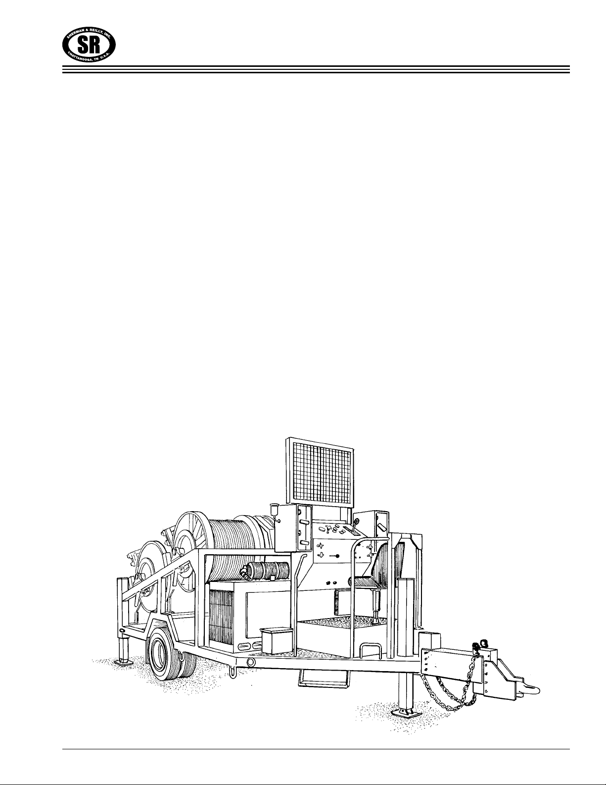
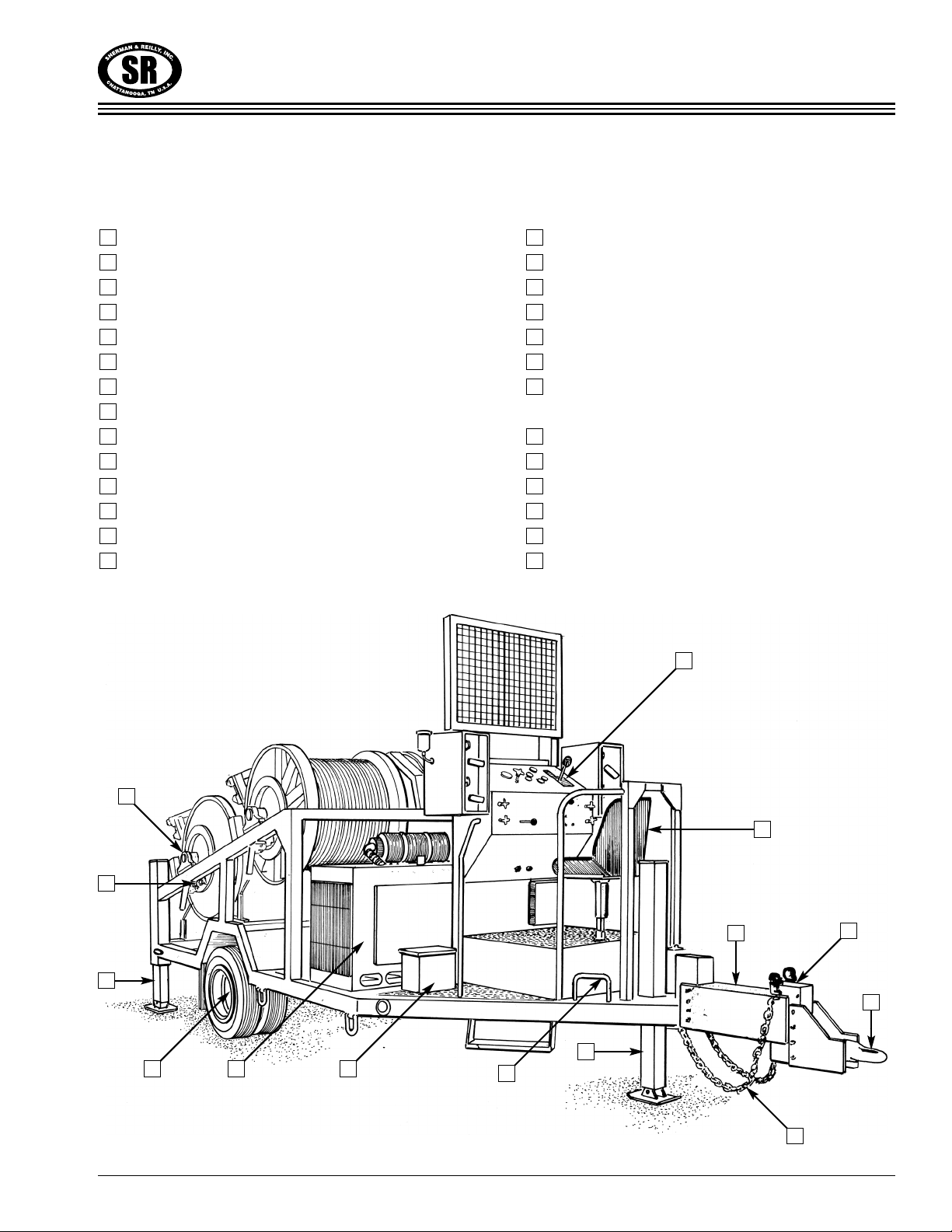
TERMS YOU NEED TO KNOW
Adjustable Pintle Eye
Safety Chains
Breakaway Safety Switch
Rear Hydraulic Jacks
Front Hydraulic Jack
rounding Loop (4 Locations)
Fuel Tank with auge
Operator Seat (Adjustable)
Engine and Cover
Hydraulic Fluid Reservoir
Hydraulic Fluid Level & Temperature auge
Operator Control Console
Reel
Reel Drive Coupling Shifter (4)
Pillow Block Housing
Payout Brake (Disc)
Fire Extinguisher
Drive Chain/Sprockets
Hydraulic Pump
Battery/Case
Hydraulic Drive Motor and
ear Box with Brake
Reel Locking Pins (4)
Axle Hub
Hydraulic Telescoping Level Wind
Suction Filter with auge
Return Filter with auge
Optional Hitch Extension
2714
26
25
24
23
22
21
20
19
18
17
16
15
13
12
11
10
9
8
7
6
5
4
3
2
1
823 20
4
22
15
6
5
7
3
12
1
27
2
3.6
Section 3 • OPERATION
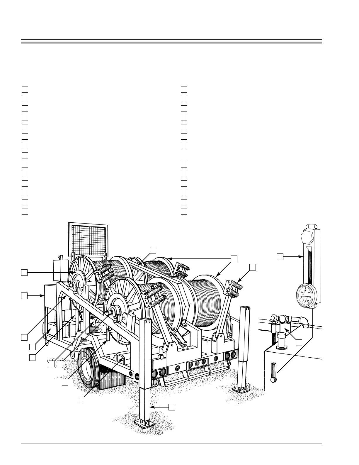
TERMS YOU NEED TO KNOW
Adjustable Pintle Eye
Safety Chains
Breakaway Safety Switch
Rear Hydraulic Jacks
Front Hydraulic Jack
rounding Loop (4 Locations)
Fuel Tank with auge
Operator Seat (Adjustable)
Engine and Cover
Hydraulic Fluid Reservoir
Hydraulic Fluid Level & Temperature auge
Operator Control Console
Reel
Reel Drive Coupling Shifter (4)
Pillow Block Housing
Payout Brake (Disc)
Fire Extinguisher
Drive Chain/Sprockets
Hydraulic Pump
Battery/Case
Hydraulic Drive Motor and
ear Box with Brake
Reel Locking Pins (4)
Axle Hub
Hydraulic Telescoping Level Wind
Suction Filter with auge
Return Filter with auge
Optional Hitch Extension
27
26
25
24
23
22
21
20
19
18
17
16
15
14
13
12
11
10
9
8
7
6
5
4
3
2
1
13
4
16
10
7
6
24
11
18
14
15
19
25
22
26

3.7
Section 3 • OPERATION
PRE-OPERATION INSPECTION
It is recommended pre-operation inspection be
done before leavin the yard or ara e.
Check fuel level on tank gauge.
Check engine oil and radiator coolant levels.
It is necessary to remove the en ine cover to
make these checks. Be sure they are replaced
and latched in position properly.
Check hydraulic fluid level in reservoir.
As you continue the inspection, look for struc-
tural dama e, bent or broken parts, cracked or
broken welds, missin pins and retainers.
Inspect pump and hoses for loose fittings,
leaking fluid, damaged hoses.
Inspect drive motor/gear box and brake.
Inspect drive chain for proper lubrication and
excessive wear.
Check chain tension and make sure the chain
guard is secure.
Inspect pillow block bearings on reel shafts (6
locations).
Inspect disc brake assemblies (4 locations).
Check reel locks for damage (4 locations).
Inspect level wind. Make sure the rollers move
freely. Check cylinders and hoses for fluid
leaks. Check for hose damage.
Make sure locking couplings operate correctly
and are not damaged (4 locations).
Start the engine
Start-Up Procedure
•Make sure all controls are in neutral and
parking brake is on.
•Start the engine.
•Refer to en ine manufacturer’s manual for
complete startin instructions.
•
•Never add ETHER to fuel to start cold en ine.
Ether WILL dama e small diesel en ines.
•Check engine oil pressure and ammeter to
be sure everything is working properly.
•Check hydraulic filter indicators (2) to be
sure the filter is serviceable.
•With the engine running, move each control
lever to make sure the lever moves easily
and the function operates correctly.
Shut the engine down.
CAUTION
NOTE
NOTE
NOTE
NOTE
TOWING (Trailer Units Only)
Connecting to the tow vehicle:
Make certain tow vehicle has the capacity and
rating to tow safely.
Inspect pintle eye and safety chains for exces-
sive wear, corrosion, cracked welds or struc-
tural damage.
Inspect tow vehicle hitch and ensure hitch is
serviceable.
Make sure trailer road brakes (air or electric)
are operable.
Do not attempt to tow if there is any question
about the service condition of the safety chains,
hitch or trailer brakes.
Make sure the unit is safe for towing with tires
in good condition and properly inflated.
Make sure reel locks are in lock position (4
locations).
Make sure engine covers securely closed.
Make sure there are no tools, objects, or refuse
which could fall off during transport.
Make sure level wind cylinder rods are retract-
ed (4 locations).
Make sure rear leveling jacks are fully retract-
ed and secured with pins and retainers.
Chock or block wheels on both sides of the
machine.
Start the engine using the
prescribed start-up proce-
dure.
Use the hydraulic jack to
raise or lower the pintle eye
to the correct height for the
tow vehicle hitch.
Open the tow vehicle hitch
and back unit into position under the pintle
eye. Set tow vehicle parking brake.
Close and secure the hitch.
The hitch coupler is a pinch point. Keep hands
and fin ers clear.
Attach the break-away switch cable to the tow
vehicle.
Connect glad hands for air brakes (when
applicable).
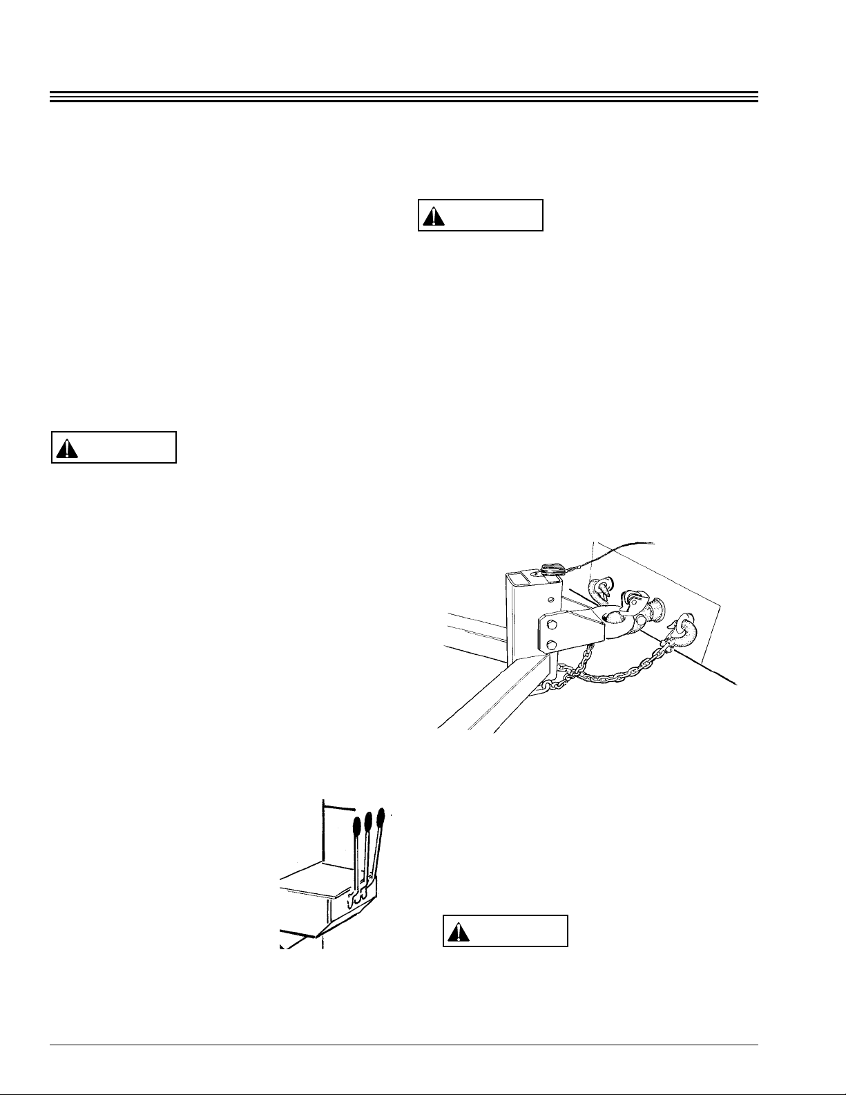
Properly connect the safety chains. The safety
chains should be crossed and short enough to
prevent the tongue from digging into the
ground, should the unit unintentionally
become disconnected. The chains should be
no longer than necessary to allow slack for
turning – crossing the chains provides direc-
tional control.
Completely retract front jack, stop engine, and
remove key.
Connect the electrical plug to the tow vehicle
and check:
clearance lights.
brake lights.
turn signals.
brakes.
Do not tow the trailer unless all lights and
brakes are working correctly.
Remove the wheel chocks or blocks.
CAUTION
CAUTION
WARNING
3.8
Section 3 • OPERATION
3.9
Section 3 • OPERATION
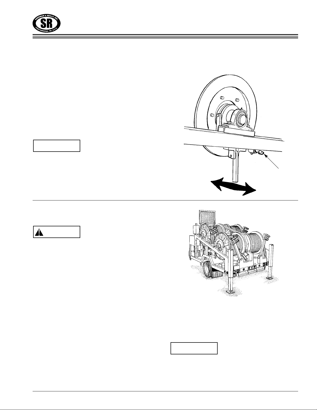
Each reel has a coupling shifter to engage and
disengage the reel. The shifter is located on the
outside of the machine near the payout brake
disc. Each lever is secured by a spring loaded
locking pin. Pull up on the locking pin to release.
For pulling, position the coupling shifter in to
engage; For pay out or free turn, position the
coupling shifter out to disengage.
There is a reel lockin pin which must be
unlatched before the reel will turn in either
direction.
NOTE
FILLING THE PULLING REEL
This unit is desi ned for a MAXIMUM rope
wei ht (not includin the reel) of 1,500 lbs. per
reel. If this wei ht is exceeded there could be
dama e to the shafts, bearin s and frame. The
machine is desi ned for SYNTHETIC PULLING
ROPES and the use of steel pullin lines may
overload the machine. Only synthetic ropes
with low elon ation such as Uniline or Sarlex
braided rope should be used. Ropes with hi h
elon ation or hi h elasticity, such as nylon, may
cause dama e to the pullin reel and should not
be used.
If the pulling reel is filled properly and the
machine is set up and leveled correctly, the
pulling rope will tend to level wind itself.
The unit is designed for overwind reeving; that
is, for the rope to wind on and off the top of the
reel.
Facing the pulling reel with your back to the first
structure, the right hand lay rope should attach to
the right hand reel flange. The left hand lay rope
should attach to the left flange the same way as
the right.
The initial fillin of the reel should be done with
the rope under li ht tension. Care should be
taken to ensure that the rope is initially level
wound on the reel.
NOTE
CAUTION
REEL DRIVE COUPLING SHIFTER
Reel Drive
Coupling Shifter
Reel Locking Pin

EMERGENCY/PARKING BRAKE
The brake is spring applied and released by
hydraulic pressure. The brake holds the gear-
box input shaft which is common to all reels
through the gearbox, chain, sprockets and reel
shafts. The drive coupling for a given reel must
be engaged for the brake to be effective for
that reel.
The brake is operated by the control valve
located on the left side of the control panel.
Push the control lever in to apply the brake
and pull out to release the brake.
Should you lose hydraulic pressure, the brake
will engage automatically.
IF YOU HAVE AN EMERGENCY
WHILE PULLING
Rotate the Emergency Brake Control lever and
simultaneously push the Reel Speed/Dir-
ection Control lever to the “Neutral” (center)
position.
3.10
Section 3 • OPERATION
PAYOUT OVERSPIN BRAKE
Each reel is equipped with a hydraulic operated
disc brake to prevent overspinning when pulling
out the rope. The brakes are mounted on the
trailer frame at the end of each reel. Rotating the
handle on the control panel clockwise increases
the braking force and counterclockwise rotation
decreases the braking force.
Pullin out the line without disen a in the
drive couplin will dama e both the earbox
and hydraulic motor.
CAUTION
Payout Brake Control
Emergency Brake Lever
This manual suits for next models
1
Table of contents
Other Sherman + Reilly Industrial Equipment manuals

Popular Industrial Equipment manuals by other brands

SCHUNK
SCHUNK ROTA THWplus Assembly and operating manual

Global
Global SV 550 operating manual

HEIDENHAIN
HEIDENHAIN ND 2100G operating instructions

WEIGH RIGHT
WEIGH RIGHT PMB-801C instruction manual

Endura
Endura 3911A02 Installation, use & care manual

HYDAC FILTER SYSTEMS
HYDAC FILTER SYSTEMS OFU-ATEX Operating and maintenance instructions


