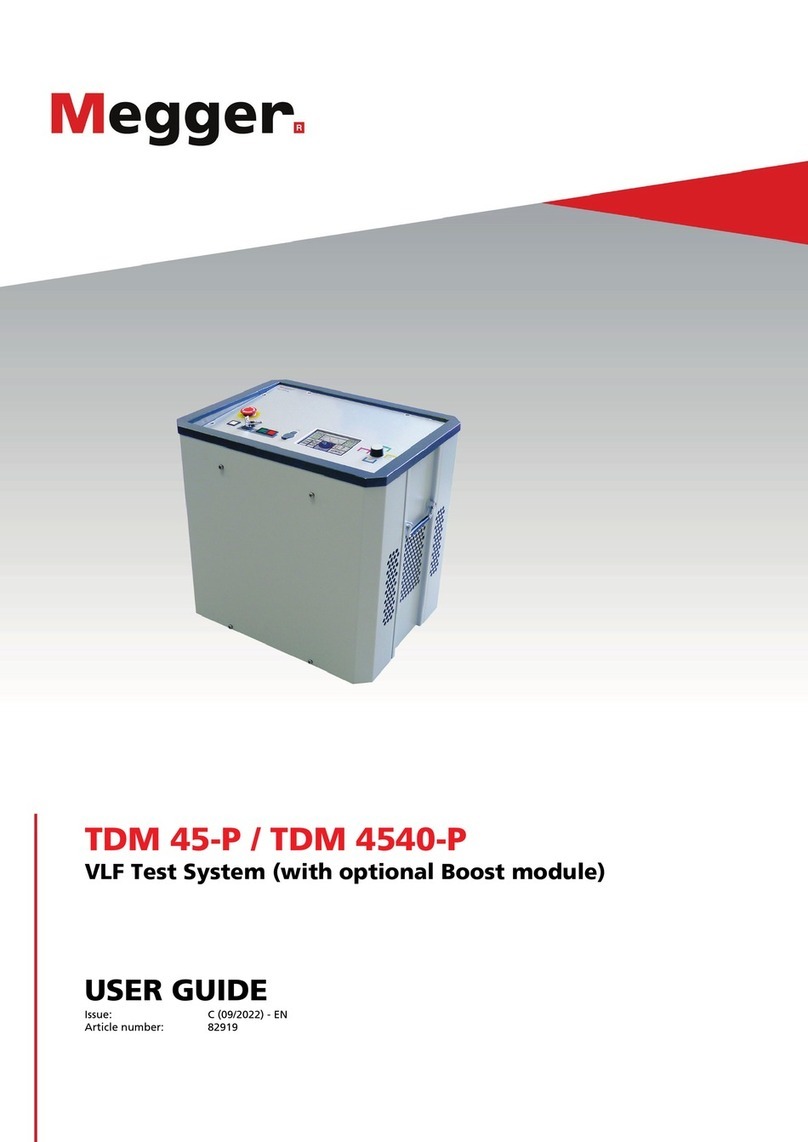
Megger VLF Sinus 62 User manual

1
VLF Sinus 62
VLF Test System
USER GUIDE
Issue: F (09/2022) - EN
Article number: 86278

2

Consultation with Megger
3
Consultation with Megger
The present system manual has been designed as an operating guide and for reference.
It is meant to answer your questions and solve your problems in as fast and easy a way
as possible. Please start with referring to this manual should any trouble occur.
In doing so, make use of the table of contents and read the relevant paragraph with great
attention. Furthermore, check all terminals and connections of the instruments involved.
Should any question remain unanswered or should you need the help of an authorized
service station, please contact:
Megger Limited Megger Germany GmbH (Baunach)
Archcliffe Road
Kent CT17 9EN
T: +44 1304 502100
F: +44 1304 207342
E: uksales@megger.com
Dr.-Herbert-Iann-Str. 6
D - 96148 Baunach
T: +49 9544 68 – 0
F: +49 9544 22 73
E: team.dach@megger.com
Megger Germany GmbH (Radeburg) Megger USA
Röderaue 41
D - 01471 Radeburg / Dresden
T: +49 35208 84 – 0
F: +49 35208 84 249
E: team.dach@megger.com
Valley Forge Corporate Centre
2621 Van Buren Avenue
Norristown, PA 19403 USA
T: +1 610 676 8500
F: +1 610 676 8610
Megger
All rights reserved. No part of this handbook may be copied by photographic or other means unless Megger
have before-hand declared their consent in writing. The content of this handbook is subject to change without
notice. Megger cannot be made liable for technical or printing errors or shortcomings of this handbook. Megger
also disclaims all responsibility for damage resulting directly or indirectly from the delivery, supply, or use of this
matter.

Terms of Warranty
4
Terms of Warranty
Megger accept responsibility for a claim under warranty brought forward by a customer
for a product sold by Megger under the terms stated below.
Megger warrant that at the time of delivery Megger products are free from manufacturing
or material defects which might considerably reduce their value or usability. This warranty
does not apply to faults in the software supplied. During the period of warranty, Megger
agree to repair faulty parts or replace them with new parts or parts as new (with the same
usability and life as new parts) according to their choice.
This warranty does not cover wear parts, lamps, fuses, batteries and accumulators.
Megger reject all further claims under warranty, in particular those from consequential
damage. Each component and product replaced in accordance with this warranty
becomes the property of Megger.
All warranty claims versus Megger are hereby limited to a period of 12 months from the
date of delivery. Each component supplied by Megger within the context of warranty will
also be covered by this warranty for the remaining period of time but for 90 days at least.
Each measure to remedy a claim under warranty shall exclusively be carried out by
Megger or an authorized service station.
This warranty does not apply to any fault or damage caused by exposing a product to
conditions not in accordance with this specification, by storing, transporting, or using it
improperly, or having it serviced or installed by a workshop not authorized by Megger. All
responsibility is disclaimed for damage due to wear, will of God, or connection to foreign
components.
For damage resulting from a violation of their duty to repair or re-supply items, Megger
can be made liable only in case of severe negligence or intention. Any liability for slight
negligence is disclaimed.
Since some states do not allow the exclusion or limitation of an implied warranty or of
consequential damage, the limitations of liability described above perhaps may not apply
to you.

Contents
5
Contents
Consultation with Megger...............................................................................................3
Terms of Warranty ...........................................................................................................4
Contents ...........................................................................................................................5
1Safety Instructions ...........................................................................................7
General Notes ....................................................................................................7
General Safety Instructions and Warnings.........................................................8
2Technical Description ....................................................................................10
System Description ..........................................................................................10
Technical Data .................................................................................................11
Load Diagram ...................................................................................................12
Scope of Delivery and Accessories..................................................................13
Display and Controls ........................................................................................15
Connection Elements .......................................................................................16
3Commissioning ..............................................................................................17
Electrical Connection........................................................................................17
3.1.1 Normal Connection...........................................................................................18
3.1.2 Using the "HVCC VLF SIN-62" connection set for automatic leakage current
correction..........................................................................................................20
3.1.3 Connection to an External Diagnosis Module ..................................................20
3.1.4 Connection via separate cable drum................................................................21
3.1.5 Use of an External Safety Device (Optional)....................................................22
Switching On ....................................................................................................23
4Operation ........................................................................................................24
Safety Circuit ....................................................................................................24
General Operation............................................................................................25
System Menu ...................................................................................................28
5Operating Modes ............................................................................................29
Cable Testing ...................................................................................................29
Sheath Test and Sheath Fault Pinpointing.......................................................33
5.2.1 Sheath Test ......................................................................................................35
5.2.2 Sheath Fault Pinpointing ..................................................................................36
VLF TanDelta Loss Factor Measurement (Optional) .......................................37
5.3.1 Preparing for Measurement..............................................................................37
5.3.2 Course of the Measurement.............................................................................40
5.3.3 Evaluation of the Test Results .........................................................................42
5.3.3.1 Automatic Evaluation........................................................................................42
5.3.3.2 Manual Evaluation............................................................................................43
TanDelta Diagnosis in Combination with the External Test Attachment..........45


Contents
6
Partial Discharge Diagnosis in Combination with a PD Coupler......................45
6Completing the Work .....................................................................................46
7Maintenance and Repair ................................................................................47

Safety Instructions
7
1Safety Instructions
General Notes
This manual contains basic instructions for the commissioning and operation of the device
/ system. For this reason, it is important to ensure that the manual is always available to
the authorised and trained operator. He needs to read the manual thoroughly. The
manufacturer is not liable for damage to material or humans due to non-observance of
the instructions and safety advices provided by this manual.
Locally applying regulations have to be observed!
The following signal words and symbols are used in this manual and on the product itself:
Signal word /
symbol
Description
DANGER Indicates a potential hazard which will result in death or serious
injury if not avoided.
WARNING Indicates a potential hazard which may result in death or
serious injury if not avoided.
CAUTION Indicates a potential hazard which may result in moderate or
minor injury if not avoided.
NOTICE Indicates a potential hazard which may result in material
damage if not avoided.
Serves to highlight warnings and safety instructions.
As a warning label on the product it is used to draw attention to
potential hazards which have to be avoided by reading the
manual.
Serves to highlight warnings and safety instructions that
explicitly indicate the risk of an electric shock.
Serves to highlight important information and useful tips on the
operation of the device/system. Failure to observe may lead to
unusable measurement results.
It is important to observe the generally applicable electrical regulations of the country in
which the device will be installed and operated, as well as the current national accident
prevention regulations and internal company directives (work, operating and safety
regulations).
After working on the system, it must be voltage-free and secured against reconnection as
well as having been discharged, earthed and short-circuited.
Use genuine accessories to ensure system safety and reliable operation. The use of other
parts is not permitted and invalidates the warranty.
The system may only be installed and operated by an authorised electrician. DIN VDE
0104 (EN 50191), DIN VDE 0105 (EN 50110) and the German accident prevention
regulations (UVV) define an electrician as someone whose knowledge, experience and
familiarity with the applicable regulations enables him to recognise potential hazards.
Anyone else must be kept away!
Safety precautions
Labelling of safety
instructions
Working with products
from Megger
Operating staff

Safety Instructions
8
The product meets the following security requirements of the European Council
Directives:
•EMC Directive (2004/108/EC)
•Low Voltage Directive (2006/95/EC)
The device must only be lifted and carried using the handles provided on the side. Other
parts of the device, such as the connecting cables, cannot withstand the forces caused
by lifting the device and could break or tear off as a result.
General Safety Instructions and Warnings
The operating safety is only guaranteed if the delivered system is used as intended (see
page 10). Incorrect use may result in danger to the operator, to the system and the
connected equipment.
The thresholds listed in the technical data may not be exceeded under any circumstances.
The equipment may only be used when working properly. When irregularities or
malfunctions appear that cannot be solved consulting this manual, the equipment must
immediately be put out of operation and marked as not functional. In this case inform the
person in charge who should inform the Megger service to resolve the problem. The
instrument may only be operated when the malfunction is resolved.
Five safety rules
The five safety rules must always be followed when working with HV (High Voltage):
1. De-energise
2. Protect against re-energising
3. Confirm absence of voltage
4. Earth and short-circuit
5. Cover up or bar-off neighbouring energised parts
Using cardiac pacemaker / defibrillator
Physical processes during operation of high voltage may endanger
persons wearing a cardiac pacemaker or defibrillator when near these
high voltage facilities.
Declaration of
Conformity (CE)
Lifting and carrying
Intended application
Behaviour at
malfunction of normal
operation

Safety Instructions
9
Fire fighting in electrical installations
•According to regulations, carbon dioxide (CO2) is required to
be used as extinguishing agent for fighting fire in electrical
installations.
•
Carbon dioxide is electrically non conductive and does not leave
residues. It is safe to be used in energized facilities as long as
the minimum distances are maintained. A CO2fire extinguisher
must be always available within electrical installations.
•If, contrary to the regulations, any other extinguishing agent is
used for fire fighting, this may lead to damage at the electrical
installation. Megger disclaims any liability for consequential
damage. Furthermore, when using a powder extinguisher near
high-voltage installations, there is a danger that the operator of
the fire extinguisher will get an electrical shock from a voltage
arc-over (due to the powder dust created).
•It is essential to observe the safety instruction on the
extinguishing agent.
•Applicable is DIN VDE 0132.
WARNING
Dangers when working with high voltage
Working on high voltage systems and equipment – especially in non-
stationary operation – requires particular care and safety-conscious
action on the part of test personnel. VDE regulations 0104 on setting up
and operating electrical test systems, as well as EN 50191 and national
standards and regulations must be strictly adhered to.
•The VLF Sinus 62 test system generates a dangerous voltage of up
to 62 kVPEAK.
•Always treat exposed connecting cables as potential electric shock
hazards.
•The test system may not be operated without supervision.
•Never fail to use safety equipment or put it out of operation.
•
Operation requires minimum two people whereas the second person
must be able to activate the emergency switch in case of danger.
•To prevent dangerous charge accumulation, earth all metal parts in
the vicinity of the high voltage equipment.

Technical Description
10
2Technical Description
System Description
The VLF Sinus 62 test system enables the standard-compliant withstand testing of
medium voltage cables and other equipment with a genuine 0.1 Hz sine wave test voltage
of up to 62 kVPEAK or 44 kVRMS.
By means of this type of withstand test, operation-endangering faults, such as
workmanship related problems, as well as insulation faults (e.g. water tree damage in
PE/XLPE cables or local damage in PILC cables) can safely be brought to failure. The
integrated breakdown detection shuts down the test voltage in the event of an excessive
charge current and guarantees limited damage to the cable.
In addition, the system is also suitable for tests with…
•positive and negative DC voltages of up to 62 kV,
•trapezoidal AC voltage (rectangular voltage) of up to 62 kVPEAK with a load-
dependent slew rate
In addition, the optional internal TanDelta measurement allows the operator, during a step
test with a sinusoidal test voltage, to determine the tanδ (TanDelta) dielectric loss factor
and accordingly get an idea about the degree of ageing of the cable.
In combination with a suitable partial discharge (PD) coupler and a notebook with the
required control software, the test system can also be used for standard-compliant partial
discharge diagnosis.
Detailed information on the features of such a PD diagnosis system can be
found in the operating manual of the used PD coupler.
The VLF Sinus 62 test system combines the following features and functions in a single
system:
•AC voltage test with two different voltage waveforms
•DC voltage test with positive and negative polarities
•Full-fledged TanDelta step test with automatic evaluation of the results
•Meaningful Voltage Withstand Diagnosis (VLF test and TanDelta diagnosis in
one step)
•Leakage current measurement in DC voltage and rectangular voltage test
modes
•Sheath test and sheath fault pinpointing with up to 20 kV negative DC voltage
•Manual and automatic frequency adjustment
•Breakdown detection with automatic disconnection of test voltage and discharge
of the test object if the charging current is too high
•Switchable burning function for fault conversion after a voltage breakdown (one
minute maximum)
•Logging (Export in Easyprot logging software via USB interface)
•Firmware updates via USB interface
•Cable screen (earth loop) monitoring
Description
Features

Technical Description
11
Technical Data
The VLF Sinus 62 test system is defined by the following technical parameters:
Parameter Value
Output voltage, sine wave 1.4 … 44 kVRMS / 2 … 62 kVPEAK
Output voltage, DC wave 2 … 62 kV
Output voltage, rectangular wave ±2 … ±62 kV
Sheath test and sheath fault pinpointing 0 … -20 kV
Source output current 40 mA
Leakage current measurement
•Display area
•Resolution
(DC and rectangular voltage)
0 to 40 mA
10 μA
Frequency 0.01 Hz to 0.1 Hz
Testable load capacitance
•Sine wave voltage
•Rectangular voltage
•DC voltage
•Maximum load capacitance
1.0 μF at 62 kV / 0.1 Hz
0.8 μF at 62 kV / 0.1 Hz
5 μF at 62 kV
10 μF at reduced voltages and
frequencies
Internal TanDelta (optional)
•Load range
•Measuring range
•Precision (requires load capacitance to
be >20 nF)
•Resolution
2 nF … 10 μF
10-4 … 100
1 x 10⁻⁴
1 x 10⁻⁵
Pulse rate in sheath pinpointing mode
(in seconds)
0.5:1 /1:2 /1:3 /1:4 /1.5:0.5
Power supply 110 V to 230 V, 50/60 Hz
Power consumption 1600 VA
Display Transflective sunlight readable 5.7" colour
display with a resolution of 640 x 480
pixels
Memory At least 1000 records of test data
Interfaces USB 2.0, Ethernet, external safety device
Weight 60 kg
Dimensions (W x D x H) 544 x 416 x 520 mm

Technical Description
12
Parameter Value
Operating temperature -20 °C to 55 °C
Storage temperature -20 °C to 70 °C
Relative humidity 93% at 30 °C (non-condensing)
Protection class (in accordance with
IEC 61140 (DIN VDE 0140-1))
I
Ingress protection rating (in accordance
with IEC 60529 (DIN VDE 0470-1))
IP21
Load Diagram
The following diagram applies to tests with sine wave voltage only and illustrates the
dependency of the test frequency on the capacity of the load connected and the test
voltage set. If a test frequency cannot be used due to the limits of the test system’s
capacity, the frequency is automatically adapted and the user is informed of this.
Cload / µF
U / kVrms

13
Scope of Delivery and Accessories
The scope of delivery of the system includes the following:
•Basic device
•Cover
•Mains power cable, 3 m
•Earthing lead, 5 m
•USB flash drive
•Accessory bag
•Operating manual
Check the contents of the package for completeness and visible damage right after
receipt. In the case of visible damage, the device must under no circumstances be taken
into operation. If something is missing or damaged, please contact your local sales
representative.
If the following optional accessories do not form part of the scope of delivery, these can
be ordered from sales:
Accessory Description Item number
Internal TanDelta
measurement
Activation of optional internal TanDelta
measurement
1009962
External safety device
with HV controls
External box with signal lights, high
voltage controls, EMERGENCY OFF
switch and key switch
108300322
External safety device
without HV controls
External box with signal lights,
EMERGENCY OFF switch and key switch
2010001
Megger Book Reporting software for Windows 2015875
TE PA-MC-UNI PD-free connection adapter
1013564 (460 mm)
1013563 (310 mm)
VLF CS-BB Set of adapters for 3-phase cable testing;
suitable for connection to busbar
128311801
External TanDelta cable
diagnosis system
External TanDelta test attachment for
very accurate TanDelta measurement
(incl. notebook, software and
accessories)
820020283
HVCC VLF SIN-62 HVCC (HV Cable Correction) connection
for leakage current correction during
TanDelta measurement
1013605
Scope of delivery
Check contents
Optional accessories
M12 and
M16
310 mm
or
460 mm

14
Accessory Description Item number
Longer HV connection
cable on cable drum
Cable drum with HV connection cable (25
or 50 m), patch panel and required
connection accessories
1013436 (25 m)
1013552 (50 m)
PD diagnosis module
PDS 62-SIN
PD coupler for partial discharge diagnosis
with sine wave voltage (incl. notebook,
software, calibrator and accessories)
1014867
Diagnostic connection
set
Accessory set for a partial-discharge free
connection to the test object
890017909

15
Display and Controls
The following control and display elements are on the front panel of the VLF Sinus 62 test
system:
Element
Description
EMERGENCY OFF switch
ON/OFF button
HV interlock key switch
“HV On” button
“HV Off” button
USB port
Display
Rotary encoder with function keys on the side

16
Connection Elements
The following connection components are located at the rear of the test system:
Element
Description
Protective earthing connection
Network port for communication with the control notebook (only required in
combination with an external diagnosis module)
Power supply socket with fuses (2 x T15A)
Socket to connect the external safety device
Guarding earth

Commissioning
17
3Commissioning
WARNING
General safety instructions for set-up and commissioning
•The safety guidelines for the operation of mobile testing systems
often differ from one network operator to another and are frequently
subject to national regulations (such as the German BGI 5191).
Before the measurement session, find out what the applicable
guidelines are and follow the rules set out therein precisely, in
respect of the organisation of work and the commissioning of the
mobile test system.
•Select a location that is sufficient for the weight and size of the
system and which ensures that it stands securely.
•When setting up or connecting the device, make sure that it does not
impair the functional capability of any other systems or components.
If other systems and components have to be modified, be sure to
reverse these measures once the work has been completed. Always
take the special requirements of these systems and components into
account and only carry out work on them after consulting and
obtaining approval from whoever is in charge of them.
•In the event of large differences in temperature between the storage
and installation locations (cold to warm) condensation may form on
components carrying high voltage (condensation effect). To avoid
any risk of damage to people and devices caused by voltage flash-
overs, the system must not be operated when in this condition. It
should rather be left in the new environment to acclimatise for
approximately one hour before putting it into operation.
Electrical Connection
WARNING
Safety instructions for the electrical connection
•The system may only be connected to de-energized
equipment. The
general safety instructions and, in particular, the five safety rules
(see page 8) must always be followed prior to connection to the test
object.
•Check the integrity of all connecting cables before use.
•Follow the specified connection sequence.
•All the cables at the measuring point that are out of operation and
are not to be tested must be shorted and earthed.
•Because the amount of voltage applied to the test object poses a
danger in the event of contact, the prohibition zone around live parts
as defined in DIN EN 50191 (VDE 0104) must be protected in a way
that it cannot be breached.
•The ends of the cables must be shielded to ensure that
contact is not
possible. When doing so, be sure to take all branches of the cables
into account.

Commissioning
18
3.1.1 Normal Connection
The following figure shows a simplified connection diagram of the test system:
Connection diagram
Station earth or other suitable
foundation earth electrode
Connection method for sheath testing and
sheath fault pinpointing
Connection method for
cable testing and loss
factor measurement
Prohibition zone and test area acc. to
DIN EN 50191 (VDE 0104)
110 V … 230 V,
50/60 Hz

Commissioning
19
Proceed as follows, to connect the test system to the test object:
Step Action
1 Using the green/yellow earth cable make a connection between the protective
earth connection of the device and a suitable point on the protective earth
system (station earth).
Make sure that the connecting points of the earth cable are not polluted /
corroded and that they provide good metallic contact.
2 If you want to carry out a cable test or a
loss factor measurement:
If you want to carry out a sheath test
or a sheath fault location:
Connect the internal conductor of the
HV connecting cable to the phase
conductor of the test object.
Connect the internal conductor of the
HV connecting cable to the earth
screen of the test object.
The earth screens must be
disconnected at both cable ends.
3 Connect the power cord included in the scope of the delivery to the system’s
power socket and a power supply socket.
Procedure

Commissioning
20
3.1.2 Using the "HVCC VLF SIN-62" connection set for automatic
leakage current correction
With the help of the optional "HVCC VLF SIN-62" connection set (see page 13), TanDelta
measurements with automatic leakage current correction can be carried out. The
connection of the set requires work on the remote cable end and must be carried out as
follows:
3.1.3 Connection to an External Diagnosis Module
In combination with a PD coupler (e.g. PDS 62-SIN) or the external TanDelta test
attachment, the test system can be expanded to a full-featured diagnosis system. For this
purpose, the test system must be connected not only to the diagnosis module itself, but
also to a control notebook (either directly or via a separate connection box).
Detailed information on how to connect to such a diagnosis module can be
found in the operating manual of the used module.
Prohibition zone and test area acc. to
DIN EN 50191 (VDE 0104)
Table of contents
Other Megger Test Equipment manuals

Megger
Megger MIT300 User manual

Megger
Megger MRCT User manual

Megger
Megger MIT221 User manual

Megger
Megger LT310 User manual

Megger
Megger OCR15D User manual

Megger
Megger SR-98 User manual

Megger
Megger T 99/1 User manual

Megger
Megger PAT410 User manual

Megger
Megger LRCD200 series User manual

Megger
Megger Easytest 20 kV User manual

Megger
Megger MIT1020/2 User manual

Megger
Megger MFT1700 series User manual

Megger
Megger PAT4DV/3 User manual

Megger
Megger OTS100AF User manual

Megger
Megger MIT415 User manual

Megger
Megger 128311841 User manual

Megger
Megger STVI User manual

Megger
Megger DET3TA User manual

Megger
Megger MEG10-01 User manual

Megger
Megger SPG 5-1000 User manual