NAG/IM/ETC 600/01/22 8
3. STANDARD DELIVERY & OPTIONAL ACCESSORIES
Standard Delivery
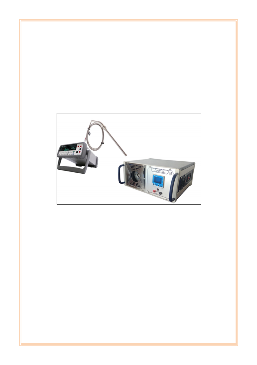
Basic Instrument
Test Leads, Mains Cable & Spare Fuses
Insertion Tubes (to suit 2 x1/4“ & 1/2“ probes)
Tool for Insertion Tubes
Traceable Calibration Certificate
Carrying Case
Instruction Manual
Optional Accessories
Additional Thermowells / Insertion Tubes (to
choose from) :
a) Single hole standard sizes to suit : 1/8”, 1/4”,
3/8”, 1/2”, 3/4” & 3, 4, 5, 6, 7, 8, 10, 12, 13,
15, 17, 19 & 21 mm probes
b) Multi hole (Typical) : (1×6 + 1×8) or (3×4) or
(1×10 + 1×4) mm
Calibration Certificates are issued in Accordance
with our Scope as granted by NABL per ISO/IEC
17025:2017 Standards
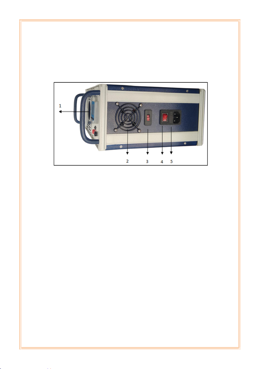
Dual Voltage Selection