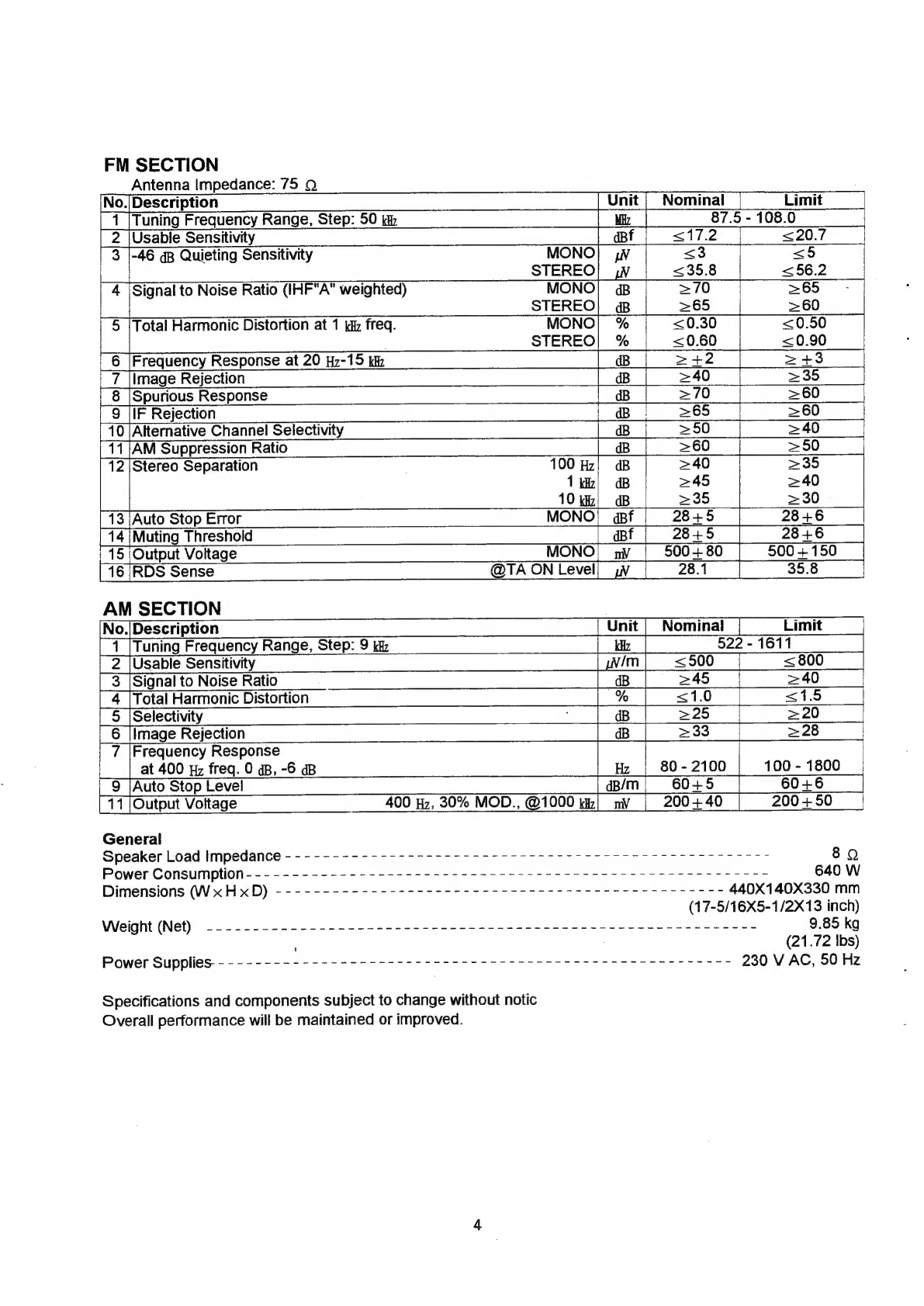
manuals.online logo
Brands
  1. Home
  2. •
  3. Brands
  4. •
  5. Sherwood
  6. •
  7. Receiver
  8. •
  9. Sherwood RV-5050RDS User manual

Sherwood RV-5050RDS User manual

SERVICE
MANUAL
RV-5050RDS
STEREO
A/V
PRO-LOGIC
RECEIVER
Sherwood
Oremume
mAi/DIC.VIDEC
RECEIVER
RV.
5050ROS
OR
2
TL
OR
PCAN
Ran,
==
© ©
©
=cee9
=a
CONTENTS
«
Safety
PreCAUtiONS------ere
eee
cere
eter
tet
tee
cece
eee
e
eee eee
2
Exploded
VIEW
cece
ee
ccc nce cen
cence
cscecncceccscccanseatece
23
Specifications
wales
Bier
care
Madicsive’s
SSbrpe
station
Suse
esses
ewes
3
Printed
Circuit
Boards
----++---
ces cee cee
cee
cee
eee
eneeneees
25
Wiring
Diagram
ee
re
er
ee
ee
5
Mechanical
Parts
List
--------eeceseeeee
eee
ceeceeceeeeeaee
31
Block
Diagram
eerrerrerer
er
er
rer
errr
errs
reer
reer
errr
eee
es
7
Electrical
Parts
List
--------+ssseeeceeees
cee
ceceesseseeeees
32
Circuit
Description
----++++-++-++eseese
reste
ee
cee
eee
cee
ee
eees
9
Semiconductor
Lead
Identification
Alignment
PrOC@dAUres
cerrer
ee
eee
cee
er
eee
cet
eee
eee
ees
17
&
internal
Diagram
BG
ESis
ob.cia
sie
do
wien
ee
ae
es
bade's
waiea
sees
38
Troubleshooting
----:eeereceeereee
ee
te
reece
eects
tees
ees
20
Schematic
Diagrams(I,
II,
I.
[V)
--++--:eseeeeee
eee
45
|
G
Sherwood
SAFETY
PRECAUTIONS
WARNING
Before
servicing
this
unit,
familiarize
yourself
with
the
following
precautions:
1.
Many
electrical
and
mechanical
parts
in
this
chassis
have
special
safety
characteristics
that
often
pass
unnoticed
and
the
protection
afforded
by
them
cannot
necessarily
be
obtained
by
using
replacement
components
Replacement
parts
that
have
these
special
safety
characteristics
are
identified
in
this
manual
and
its
supplements:
electrical
components
having
such
features
are
identified
by
/A\
in
the
schematic
diagram
and
the
parts
list.
Before
replacing
any
of
these
components,
read
the
parts
list
in
this
manual
carefully.
The
use
of
substitute
replacement
parts
that
do
not
have
the
same
safety
characteristics
as
specified
in
the
parts
list
may
create
shock,
fire,
or
other
hazards.
2.
Before
returning
the
set
to
the
customer,
always
do
an
AC
leakage
current
check
on
the
AC
Outlet
At
5000
Q
per
volt
or
greater
sensitivity,
the
reading
should
not
exceed
0.75
V.
0.15
pF,
150
V
AC
Place
the
probe
on
each
exposed
metalic
part.
exposed
metal
parts
of
the
cabinet,
such
as
terminals,
screw
heads,
and
metal
overlays,
to
be
sure
the
set
is
safe
to
operate
danger
of
electrical
shock.
Plug
the
AC
line
cord
directly
into
a
230
V
AC
outlet.
(Do
not
use
a
line
isolation
transformer
during
this
check.)
Be
sure
your
AC
voltmeter
has
a
sensitivity
of
5000
Q
per
volt
or
greater.
Then
connect
a
1500
2
10
watt
resistor,
paralleled
by
a
0.15
uF
150
V
AC
capacitor,
between
a
known
good
earth
ground
(such
as
a
water
pipe,
or
conduit)
and
the
exposed
metalic
is
parts,
one
at
a
time.
Measure
the
AC
voltage
across
the
combination
of
a
1500
Q
resistor
and
a
0.15
uF
capacitor.
Reverse
the
AC
plug
at
the
AC
outlet
and
repeat
AC
voltage
measurements
for
each
exposed
metalic
part.
Voltage
measured
must
not
exceed
0.75
V
RMS.
This
corresponds
to
0.2
mA
AC.
Any
value
exceeding
this
limit
constitutes
a
potential
shock
hazard
and
must
be
corrected
immediately.
AC
Voltmeter
Good
earth
ground,
such
as
a
water
pipe
or
conduit.
SPECIFICATIONS
FRONT
AMP
SECTION
Condition:
DOLBY
PROLOGIC
off.
No.|
Description
Unit
|
Nominal
Limit
|
|
1
|RMS
Output
Power(mode:
STEREO)
both
channels
driven
at
40
Hz-20
up
freg.,
0.7%
THD,
8
Q
load.
>82
>80
2
|Inter
Modulation
Distortion
(60
Hz:7
du=4:1
SMPTE)
L
at
8
©
load,
80
W
output.
%
<0.05
<0.08
3
|Input
Sensitivity
PHONO!
py
|
2.8
+
0.35
2.8
+
0.4
I
at
1
Miz
freq.,
47
kQ
Impedance.
CD,ETC)
my
|
170
+
20
170
+
30
|
4
|PHONO
Input
Overload
at
1
ki
freq.,
0.5%
THD
nV
>140
>120
5
\Frequency
Response;
at
8
©,
1
W
output,
30
-
15000
Hz
---------------
>
PHONO!
gp
|
RIAA
+1.0
RIAA
+1.5
|
ats
©,
80
W
output,
-3
aB-
------------------->CD,
TAPE)
Hz
|
10-60000
20-50000
|
6
[Signal
to
Noise
Ratio
IHF"A"
weighted
PHONO,
gp
=70°
|
>66
at
8
©,
1
kz,
80
W
output
CD,
AUX;
@B
>90
>
85
7
|Tone
Control
at
8 Q,
1
W
output
BASS:
100
Hz}
«GB
10+1.8
+1042
|
TREBLE:
10
kh]
oB
10+1.8
+1042
8
[Channel
Separation
at
8
Q,
80
W
output
100
Hz!
oB
>50
j
>40
Input
shorted,
CD,
TAPE
1}
oB
>50
>40
oe
10k
B
|
>45
>35
9
{Crosstalk
at
8
O,
1
kd
freq.,
80
W
output
CD=>TAPE1|
gB
>65
>50
|
Input
shorted
TAPE=CD,|
oB
>60
>50
10
|Sub
woofer
output
at
CD,
1
kh,
170
ny
input
|
nV
900+100
|
900+150
|
11
[Headphone
output
at
1
kz,
1
W
Speaker
output
33
Q
Load]
my
|
200430
200
+
50
10
|
Total
Harmonic
Distortion
40
fz)
%
<0.05
<0.2
at
8
Q
load,
80
W
output
1kk|
%
<0.05
<0.2
20k)
%
|
<0.2
<0.3
REAR
AMP
SECTION
Condition
input:
CD,
Input
level:
1
Kaz
freq.
230
nv,
Rear
level:
Max.,
Mastar
Volume:
adj.
No.|Description
Unit
|
Nominal
Limit
1
|RMS
Output
Power(1
CH.
driven
80
W)
|
at
1
iz
freq.,
8
Q
load
|
%
|
<0.8
<1
|
2
|Frequency
Response
>80-
7000)
+100
-
7000
at
1
W
output,
+3
dB,
WIDE
MODE
|
Hz
(+
500)
(+1000)
3
|Signal
to
Noise
Ratio(IHF"A”"
weighted)
Delay
time:
20
ms
DOLBY|
dB
|
265
>60
|
CENTER
AMP
SECTION
Condition
Input:
CD,
Input
level:
1
Wz
freq.
220
ny,
Center
level:
Max.,
Mastar
Volume:
adj.
No.|/Description
Unit
|
Nominal
|
Limit
|
1
‘RMS
Output
Power(1
CH.
driven
80
W)
aes
|
at
1
kHz
freq.,
8
©
load
|
%
<0.2
|
<0.4
2
|Frequency
Response
|
at
1
W
output,
-3
qB,
DOLBY
NORMAL}
Hz
|100-17000)
150-15000
|
|
WIDE}
Hz
|
30-
17000
50-15000
|
|
3
[Signal
to
Noise
Ratio
(IHF"A"
weighted)
NORMAL)
4B
>78
>70
|
VIDEO
SECTION
(No.
Description
|
Unit
|
Nominal
Limit
|
1
[Input
Sensitivity/impedance
|
dB
|1Vp-p/75
O
+0.5
L
2
|Output
Level/impedance
[
gB
1
Vp-p/75
9
+0.5'
|
3
|Frequency
Response
5
Hz
-6
M|
4B
+2
+3
4
|Crosstalk
1.0
Wm
dB
>45
|
>40
[
5
{Signal
to
Noise
Ratio
|B
345
>40
FM
SECTION
Antenna
Impedance:
75
QO
AM
SECTION
No./Description
Tuning
Frequency
Range,
Step:
9
kz
Usable
Sensitivity
Signal
to
Noise
Ratio
>|
Cy
Fy)
Go}
PO]
Unit
Kz
/m
dB
%
No.|/Description
Unit
|
Nominal
Limit
1
[Tuning
Frequency
Range,
Step:
50
kt
Miz
87.5
-
108.0
2
|Usable
Sensitivity
df
<17.2
<20.7
3
|-46
gB
Quieting
Sensitivity
MONO]
iW
<3
<5
STEREO
<35.8
<56.2
4
|Signal
to
Noise
Ratio
(IHF"A"
weighted)
MONO!
«B
>70 >65
=-
STEREO}
aB
>65 >60
5
|Total
Harmonic
Distortion
at
1
kd
freq.
MONO!}
%
<0.30
<0.50
STEREO|
%
<0.60
<0.90
6
/Frequency
Response
at
20
Hz-15
kh
dB
>4+2
>+3
7
|Image
Rejection
dB
>40
>35
8
|Spurious
Response
dB
>70
>60
9
|IF
Rejection
|
dB
>65
>60
10
|Alternative
Channel
Selectivity
dB
>
50
>40
11/AM
Suppression
Ratio
dB
>60
>50
12
|Stereo
Separation
100
Hz;
B
>40
>35
1k!
«B
>45
>40
10
Wz}
GB
>35
>30
13
|Auto
Stop
Error
MONO
|
apf
28+5
28+6
14
|Muting
Threshold
dbf
2845
28+6
15
|Output
Voltage
MONO)
nv
500
+
80
500
+
150
16
|RDS
Sense
@TA
ON
Level
28.1
35.8
Nominal
522
-
1611
<500
>45
<1.0
|
1
|
Tuning
Frequency
Range,
olep.
9
kip
CNS
|
2
|Usable
Sensitivity
SO
SON
Total
Harmonic
Distortion
Selectivity
i
dB
>25
>20
Image
Rejection
dB
>33
>28
<800
>
40
<i5
7
|Frequency
Response
at
400
yz
freq.
0
dB,
-6
aB
Hz
80
-
2100
100
-
1800
9
|Auto
Stop
Level
dB/m
60+5
60+6
11
|Output
Voltage
400
Hz,
30%
MOD.,
@1000
rz!
nv
200+
40
200+50
=|
General
Speaker
Load
Impedance
-
-
- -
-
-
--
-------------------
5-2
r
rrr
rrr
rrr
rrr
r
rrr
8Q
Power
Consumption
-
-
-
-
-
--
-------------------------------------------------
640
W
Dimensions
(WxHxD)
--------------------------------
2-2-0025
-
ree
(17-5/16X5-1/2X13
inch)
Weight
(Net)
-----------------------------------------------------------
Power
Supplies
-
-
---------------------------
7-2-5
-rr
rrr
crc
errr
cre
Specifications
and
components
subject
to
change
without
notic
Overall
performance
will
be
maintained
or
improved.
440X140X330
mm
9.85
kg
(21.72
Ibs)
230
V
AC,
50
Hz
AC
INPUT
POWER
TRANS
OOD00000
000
eee
TRANS
B’D
4001001430
CN1i04
(PCB7)
PWA
SW
B’D
4001001440
SPK
A.B
HEADPHONE
8’
D
400
10041630
(PCB10)
CN10S
WIRING
DIAGRAM
(PCB11)
(PCB2)
PRE-IN
OUT
B’D
400
1001650
yv
is
SURROUND
SPK
&
VIDEO
B’D
4001002910
CN205
cP2i0
HEAT/SINK
8beNOD
4001002360
MAIN
B’'D
[dE
]
o
Cc
3
bO
oc
Oz
>
o°
ies
we
on
Oo
6YeCNO
CN221
4001004400
FRONT
8°D
(PCB3)
jo]
jo]
©
=<
°
°
=
°
(°]
v
CNe1i
CN212
CNe1i3
QP
6P
4001001420
SURRE&
VOL
B’
D
(PCB4)
alc
A
S
oO
Al
(PCBS)
i
CP2i7
SP
TAPE2
B’'D
4001004620
TUNER&
ROS
B’
D
Model
No.
:
RV-5050RDS
CN216
4001001610
(PCBS)
cP2i3
CP221
4001001410
ANT
n
x
AM
rs
|
TUNER
OO
more
O
0
©
cotvep)
1
Oo
©
A
TAPE
1
[
om
°o
©
©
CO
v
eset
:©
OD
tapee
[
MON
fe)
I
(1C¢101/102)
6
I
VCR
[
vcR
1
REC
°
vVCRe
—
REAR
4
I
DB
ver:
[
fe]
E
0
GO4066
vere
ie
REAR
MONITOR
Out
BLOCK
DIAGRAM
pe
RES
Se
Sea
ee
eee
re
ay
ees
toe
5
1
|
rs
Plo]
=
START
ap
'
DEMODE
.
CECODE
AbS-
eo
t
_
:
*DA73306
LC7O73
1
\
LA1235
1
SIGNAL
METER[
1
oo
Dt
svu
|
7
3
DATA
CLK
cE
TUNED
STEREO
a
MUTE
eorora
ae
LA3410
ia
my
[Doe
aM EM
L.P.F
iA
7
ea
PRO
LOGIC/Z
‘
3
STEREO
x
DOLBY
PRO-L.OGIC
ADAPTIVE
MATAIX
NUM
2177A
[(IC501)
DIGITAL
DELAY
NUU
9701
(IcSO3)
FL
CPU
(ic505)
SHIFT
REGISTER
MC
14094
INPUT
PaRT
SLRROUND
PART
TUNER
PART
MAIN
PART
POWER
PART
Se
BALANCE
O
|
vou.
Bae=sue:
oMAINZEN
)
Tcosess
N
Model
No.
:
RV-5050RDS
RESOR
KEY
—NATOR
MATRIX
DIG:
DISPLAY
LINK
O
RMC
SENSOR
|
<L~
(|
commences
|
Y
RELAY
PEs
;
CP
ij
niezon
-27v
'
\
REGULAT
ae
FL
ac
3.5v
4
ST-BY
RELAY
+12v
<
REGULATOR
-12V
12v
-iev
+
BV
Sv
FRONT
AMP.
2
AMP
CENTER
AMP,
<A
POWER
REAR
amp.
SUPPLY
REGULATOR
Sv
POWER
Sw
ac
INPUT
OC
R
WOOFER
OuT
L
HEAO
PROTECT
PHONE
A
©
STEREO
MODE
GOW
X
2
SURA
MODE
SOW
x
2
MUTE
CH
MUTE
B
CENTER
PRE-OuT
+
DISCRETE
CENTER
AMP
CENTER
SOW
PROTECT
REAR
25wx2e
DISCRETE
RESAR
AMP
CIRCUIT
DESCRIPTION
1C201
:
uPD78044AGF-152
(8bit
CMOS
Microprocessor)
1.
Pin
Configuration
GRID
KEY-OUT
Sit
G7
$12
G8
$13
$14
G10
$15
G11
(6)
S16
G12
7)
ViD4
Voo
(8)
vib2
CLK-7073
(9)
RDS
MODE
DATA-7073
(10)
VOL
DOWN
CH
MODE
@)
uPD78044GF-152
VOL
uP
aes
(2)
T
MUTE
ST-9216
413)
Voo
CLOCK
(14)
=~
viD3
DATA
@9)
ST-4094
ST-7821
-———(6)
ST-BY
LED
RESET
(7)
Vss
$T-9701
48
RMC
Sis2299
a9)
DB
LINK
AVss
20
PWR
DOWN
STEREO
@1)
DATA
7073
VIDS
22)
KC/TOO
VID4
3)
KuUTO1
RDS
IN
(24)
K2/TO2
25{26)27)-+28)-29)-B0)-3
1)-
82-33-34)
85)-38)-G7)-38)-39)
40)
Pied
Beene
Rae
We
Ae
ddd
he
deal
x=
—
to.
“<>
cr
See
Beh
See
Ni
|
Mere
Be
ye
Sir?
2
fee
eS
ee
Oe
KEY-IN
i
on
Ss
=
z
pC
‘al
:
£
8
;
Up}
2.
Pin
Functions
Pin
No.
|
Symbol
Description
RE
Logic
|
1-7
GRID
6-12
|
Grid
signal
output
for
FIP.
ae
;
8
VDD
+5
V
power
supply.
9
CLK-7073
=|
Clock
port
of
LC7073.
10
DATA-7073
Data
port
of
LC7073.
11
CH-MODE
Control
port
for
Dolby
Pro-Logic
Channel.
H
12
ST-BY
When
the
power
is
on,
control
data
output
is
"H".
|
When
the
power
is
off,
control
data
output
is
"L"
|
and
last
memory
is
actived.
13
ST-9216
Strobe
port
of
TC-9216.
14
CLOCK
|
Clock
output.
=a
15..|.
DATA
|
Data
output.
16
|
ST-7821
Strobe
port
of
LC-7821.
17
RESET
|
Input
for
resetting
CPU.
18
ST-9701
Strobe
port
of
NJU-9701.
|
t
—{__—-
——4
19
ST-9299
|
Strobe
port
of
TC-9299A.
20
|
AVss
Ground
21
STEREO
Input
for
detecting
FM
STEREO.
H/M/L
22!
VID5
|
Control
port
of
VCR2
front
and
rear.
23-554
VID4
Control
port
of
VCD.
|
24
RDS
IN
Strobe
port
of
TDA-7330B
RDS
input.
L
25
|
PROTECTION
|
Signal
input
for
protection.
26
COC;
TUNED
Input
for
detecting
the
station
during
tuning.
L
27
|
STEP
According
to
the
region,
input
for
selecting
the
frequency
bands
and
steps
of
FM
and
AM.
Settings
are
as
follows.
REGION|
FREQUENCE
|
STEP
|
PIN
27
|
|
|
AMERICA|FM:
87.5
-
107.9
MHz}
200
KHz)
5V
|
|
AM:
520-1710
KHz
|
10
KHz
|
|
EUROPE
|FM:
87.5-108MHz
|
50KHz|
2.5
V
L
i
522-1611
KHz
|
9
KHz|
|
KOREA
|FM:
87.5
-
107.5
MHz)
200
KHz}
OV
|
|AM:
522-1611
KHz
|
9
KHz
28
|SIGNAL
METER’
Input
port
of
FM
Signal.
H/L
i
29
AVaag
|
Power
supply
of
Analog
A/D
Converter.
“a
|
30
AViet
|
Ref.
Voltage
of
Analog
A/D
Converter.
L
31
GND
Ground.
|
32
N.C
|
Not
used
!
a
Vss___
Ground.
34
X-TAL
IN
Input
for
crystal
oscillator.
|
35
X-TAL
OUT
|
Output
for
crystal
oscillator.
z
36
C.MUTE
'
Control
port
for
Center
Signal
mute.
H/L
37
S.MUTE
Control
port
for
Surround
Signai
mute.
H/L
38
T/M
MUTE
Control
port
for
Tape
Monitor
Signal
mute.
39
M.MUTE
Control
port
for
Main
Signal
mute.
H
10
;
Active
Pin
No.
|
D
ipti
|
No
|
Symbol
escription
|
Logic
oT
:
40
-
43
K3
-
KO
Data
input
for
key
scan.
H
DATA
-
7073
Data
start
of
LC-7073.
45
PWR-DOWN
Input
for
detecting
power
down.
L
D-LINK
Input/Output
for
controlling
DIGI-LINK.
47
RMC
input
for
remote
control
data.
aay
Vss
Ground.
ST-BY
LED
Output
for
driving
stand-by
LED.
H
50
ST-4094
Strobe
port
of
M-14094.
H
51
52
[Vn
|
*5V
power
supply.
53
Output
to
drive
volume
motor
for
increasing
volume
level.
VOL.DOWN
|
Output
to
drive
volume
motor
for
decreasing
volume
level.
56
RDS
MODE
Control
port
for
RDS
mode.
mB
Ij
x
57
VID2
Control
port
for
VCR2
hie.
58
viD1
Control
port
for
VCR1.
59
-
70
SEG
16-5
Segment
signal
output
for
FIP.
71
Vioad
-30
V
power
supply
for
FIP.
SEG
4-1
Segment
signal
output
for
FIP.
76
-
80
GRID
1-5
Grid
signal
output
for
FIP.
fe
3.
Block
Diagram
TOO/PI0
O=—]
isbnTIMEN
[A
TO1/P31
O
8
ba
TIMER/
==
Ti1/P33
0
EVENT
COUNTER
|
K
>
POO-PO4
TO2/P32
T12/P34
Bbit
TIMERS
K—
sence
[ef
vom
/
WATCHDOG
TIMER
K
—_
>
“WATCH
TIMER
[rome
F>
mm
CIO/INTP3/PO3
oe
Een
ae
f
COUNTER
coms
om
aa
el
2
em
E>
vom
eee
intenraceo
K—Y
PORTIO
[-_
>
P100-P107
SCKO/P27
s1/P20
©
s01/P21
©
BeRL/P22
owe]
SERIAL
YA)
|
|
puzzer
[SOCK
|
crock
|
cock
cavmaror
|
sranp
By
INTERFACE
1
OUTPUT
stB/P23
©
OUTPUT
DIVIDER
|
sus
|
CONTROL
BUSY/P24
©
CONTROI.
Ko
PorTID.
«KC
pino-P17
O
O
AYa,
O
ANIO/P10.
a,
a
BUZ/P36
PCL/P35
PO4/XT1L
XT2
AVps
O-—~-|A/D
CONVERTERK
—_
;
ate
Cy
rome
kD
P120-P127
oe
°
|
i
|
|
INTPO/TIO/POO
INTERRUPT
FIPO-FIP33
Lath
|
conmo.
K—~
FE
Mae
Se
vi
~INTP3/Cl0/PO3
O
Vreso
11
4.
Key
Matrix
OUT|
KSCANO!|
KSCAN1
|
KSCAN2/
KSCAN3/
KSCAN4|
KSCANS5
|
KSCAN6
|
KSCAN7
IN
PIN
61
PIN
62
PIN63
|
PING4
|
PINGS
|
PIN66
|
PIN67
|
PIN68
[
eS
PUN
KEY
INO
|
DISPLAY
AM
TAPE
1
|
TAPE
2
CD
4
VCR2
>
VCR1
PIN
43
|
{DCC
|
MON.
|
Fora
ec
ae
eal
rr
ONO
FM
4
2
DIRECT
A
Sia
|
(RDS
PH
|
v
SS
STE
USE
SERRE
RE
eee
eee
KEYIN2|)
AF
CENTER
5
9
3
6
PIN
41
MODE
|
KEYIN3|
DTY
|
SURROUND
o
|
8 7
MEMORY
|
AUTO
FM
PIN
40
MODE
|
/IMANU
|
MODE
le
5.
Digital
Tuning
System
Description
<QquE
FV
PLL
Loop
<7]
AM
PLL
Loop
FM
ANT
___FM
FRONT
END
PACK
r
—
vee
eens
Ge
ome
ee
om ee
ee
ag
FM
RF
FM
MIX
FM
OSC
|
Keay
I
Low
Pass
Filter
Q902,
Q903
ai
PLL
Prescaler
FE
901
FM
IN
1C901
AM
IN
CCT
Sr
we
Se
we
=
AM
ANT
Data
CPU
1C201
AM
OSC
Key
FL
;
[Butler
|
!
Display
Switch
Matrix
!
I
I
|
!
|
1
i
|
1
I
1
|
!
i
i
L
12
«
Vco
vs.
FM
Band
Frequency
Curve
Po
RE
bel
yop
eto
|
ge
eT
Te
ee
EMER
ES
EERE
RARER?
AES
glibc
Meaty
tes
Te
foe
te
Ca
We
a
ea
A
ge
sea
eee
ae
Ae
ee
Ae
eee
ee
eee
ee”
eee
=
pop
fo
fpf
ttt
AP
Bo
og
ae
ee
Be
eee
ea
ae
oy
eS
a
nn
nee
cee
eee
eee
g
tt
et
Pe
a
i
a
Ha
a
AO
SERRE
=
«eee
Ree
eee
olde
eer
pole
Nee
bole
lael
pad
tear
Paa EeD
P
hea
|
2
See
eee
Sect
cI
A
ae
eal dea
sled
ed
he
peuple
a
ahs
|
Pi
eC
a
ee
875
895
915
935
95.5
975
99.5
101.5
103.5
105.5
107.5
FM
Band
Frequency(MHz)
¢
Vco
vs.
AM
Band
Frequency
Curve
Ams.
NEE
SERER
N
|
|
IN
Pan
|_|
Vco
Voltage
(V)
uo
SREP
HSER
RRR
ER
Bana”
de
Se
RaSh
ARR
ha?
Shh
eae
eee
eee
ft
ep
tf
520 600
700
800
900
1000
1100
1200
1300
1400
1500
1600
4RR@
if
Hae
ee
eaes
Sh
RARER
SR
RARER
SERRE
ae
AM
Band
Frequency
(kHz}
13
6.
Level
Diagram
Volume
Balance
Speaker
val
cal
Volume
P
ff
Amp
O)
out
25.6V}
82W
80
8Q
70
28.8dB
60
50
ee
0.12dB
0.12V
35.5dB
0.028V
Audio
Frequency
(1kHz)
Voltage
Gain
in
dB
14
7.
Protection
Circuits
¢
Speaker
Protection
Circuits
The
CPU
protects
both
this unit
and
the
speakers
when
an
abnormally
high
current
fllows
in
Q309
L/R/C/S
and
0310
L/R/C/S
due
to
excessive
input
drive,
too
low
of
a
load
impedance,
or
short
of
the
speaker
terminals.
If
current
increase
is
excessive
the
voltage
across
R316
L/R/C/S
turns
on
0312
L/R/C/S,
then
0313
turns
and
0314.
It
makes
the
protection
port
of
the
CPU
to
low
state,
and
the
CPU
turns
off
Q317
and
Q316.
Then
this
unit
goes
to
stand-by
mode.
A
Os,
A
0312
Kd
TO
CENTER/REAR
CHANNEL
Se
620
10/50
+12
fT)
'
\
a
H
=
\
R337
‘
:
eal
TO
SURROND
22K
:
SPEAKER
B'D
1
IN4148
&
Ea
]
:
TO
INPUT
B'D
22K
R339
TO
CPU
22
Q314
|
R338
(PROTECTION)
0314
K7\03198
33K
+
‘
|
ole
Ss
meta
fi’
c3198
i
%
WR,
/
0315
R331
R333
TO
R
CHANNEL
TO
BIAS
SUPPLY
TO
BIAS
Q317
2$D1302
15
«
Thermal
Protection
Circuits
This
receiver
has
a
overload
thermal
protection
circuits
to
guard
against
abnormal
operation.
When
the
temperature
of
TRANS
POSISTOR
installed
with
the
main
transformer
rises
abnormally,
the
resistance
of
the
posistor
becomes
larger
and
0314
is
turned
on.
It
makes
the
protection
port
of
the
CPU
to
Low
state,
and
the
CPU
turns
off
0317
and
0313.
Then
this
unit
goes
to
stand-by
Mode.
22K
be
Q314
TO
CPU
R330
3198
R338
So
(PROTECTION)
ise]
a)
f-
0315
°
&
ak
law
b)
C3198}
45
Sees
ft-
C314
ote
8
1
)
=
>
0.047(M)
|
R336
3K
56)
CN106
[es
TRANS
POSISTOR
7.5K
R335
B.8V
D309
TO
BIAS
SUPPLY
TO
BIAS
TO
CPU
(ST-BY)
Q317
2801302
16
ALIGNMENT
PROCEDURES
Adjustment
and
Test
Points
(Tuner
P.C.
Board)
17
Before
adjustments,
refer
to
‘Adjustments
and
Test
Points"
on
Page
17.
Note:
As
a
front-end
(FE901)
is
difficult
to
repair
if
faulty,
replace
it
with
new
one.
FM
SECTION
«
Standard
Setting
of
FM
stereo
RF
Signal
Generator.
STEREO
STANDARD
SIGNAL
Carrier
frequency
:
98.0
MHz
Modulation
:
Audio
1
kHz,
40
kHz
deviafion.
Pilot
19
kHz,
7.5
kHz
deviation
MONAURAL
STANDARD
SIGNAL
98.0
MHz
1
kHz,
45
kHz
deviation
FM
Discriminator
Adjustment.
(NULL
and
MONO
Distortion)
FM
RF
stereo
signal
Distortion
generator
meter
Output
level:
ImV
(50
dBu)
Antenna
FM
(7592)
Tape
1
Won
Output
{DC
range)
(NULL)
TP2
=
TP3
Procedure
:
1.
Tune
the
set
to
98.0
MHz.
2.
Adjust
L903
for
0
V
reading
on
the
VOM.
--NULL
3.
Adjust
L904
for
a
minimum
reading
on
the
distortion
meter.
-+-+-+++-+++++-
MONO
Distortion
4.Repeat
the
adjustments
of
2
and
3
several
times.
Note
:
When
replacing
the
ceramic
filter,
perform
this
alignment.
FM
Stereo
Distortion
Adjustment
FM
RF
stereo
signal
Distortion
generator
meter
6
dB
Loss
——4
[7]
————_—_—_—_—o+
set
“T_T
oo
2
+
ae
Antenna
FM
(75)
=
Tape
1
Output
Mode
:
stereo
Output
level:
1
mV
(60
dBu)
Procedure
:
:
1.
Tune
the
set
to
98.0
MHz.
Set
SSG.
output
level
to
1
mV
(60
dBu)
2.
Adjust
IFT
in
FE
901
for
a
minimum
reading
on
the
distortion
meter.
18
FM
Tuned
Indication
Lighting
Level
Adjustment
FM
RFF
stereo
signal
generator
Output
level
:
7
uV
(17
dBp)
Set
FM
Antenna
teminal
(75
$2)
Procedure
:
1.
Tune
the
set
to
98.0
MHz.
Set
SSG
output
level
to
17
dBu.
2.
Adjust
VR
902
to
the
place
where
"TUNED"
indicator
lights.
FM
Stereo
Separation
Adjustment
FM
PF
stereo
signal
generator
Mode
:
stereo
Output
level
:
1
mV
(60
dBu)
Antenna
FM
(75
92)
Tape
1
Output
Procedure
:
FM
stereo
signal
generator
output
channel!
VTVM
VIVM
reading
(dB)
connection
®
Adjust
VR903
minimum
reading.
R-CH.
|
R-CH.
©
©
L-CH.
R-CH.
|
Adjust
VR903
for
minimum
reading.
L-CH.
Stereo
separation:
©
—
®
R-CH.
Stereo
separation:
©
-
D
The
separation
of
both
channels
should
be
equal.
AM
SECTION
AM
RF
signal
generator
I
|
{
:
—_—_—_—P:
f
60cm
|
|
26dBLoss
;
AM
loop
antenna
30%
amplitude
modiulation
by
400
Hz
signal
Output
Level
:
80
dB(+26
dB
Loss)
603
kHz,
999
kHz,
1404
kHz
AM
loop
antenna
AM
antenna
terminal
dBy/m
=
(SSG
output
level)
-
26
dB
AM
Vrt(Tunning
Voltage)
Adjustment
1.
Set
to
AM
522
kHz
and
adjust
L902
so
that
voltage
of
TP1
becomes
1.1V
+0.05V
2.
Set
to
AM
1611
kHz
and
adjust
TC902
so
that
voltage
of
TP1
becomes
8.4
+0.05V
3.
Repeat
the
above
adjustments
1
and
2.
AM
Tracking
Adjustment
AM
RF
signal
generator
30%
amplitude
modulation
by
400
Hz
signal
AM
loop
antenna
AM
antenna
terminal
dBu/m
=
(SSG
output
level)
-
26
dB
1.
Set
to
AM
603
kHz
and
adjust
L901
to
maximize
AUDIO
output
level.
2.
Set
to
AM
1404
kHz
and
adjust
TC901
to
maximize
AUDIO
output
level.
3.
Set
to
AM
999
kHz
and
adjust
L905
to
maximize
AUDIO
output
level.
4.
Repeat
the
above
adjustments
1,
2
and
3.
AM
TUNED
Level
Adjustment
Procedure
:
1.
Set
SSG
output
level
so
that
antenna
input
level
of
the
set
becomes
630
pV
(56
dByu/m).
2.
Adjust
VR901
to
the
place
where
"TUNED"
indicator
lights.
TROUBLESHOOTING
Symptom
Receiver
inoperative
(FL
indicator
does
not
light)
Fuse
blows
when
power
is
turned
on.
Power
indicator
lights
but
no
sound
from
both
channels
Speaker
A
inoperative
Speaker
B
inoperative
One
channel
does
not
work
when
volume
is
at
maximum
with
a
test
signal
applied
to
the
center
terminal
of
volume
control
VR5
of
the
dead
channel.
Speaker
works
normally
but
headphones
inopertive.
PHONO
input
inoperative
FM
inoperative
Cause
and
Remedy
A)
Faulty
AC
power
cord.
Replace.
°
B)
Defect
in
the
power
switch.
Replace.
C)
Broken
wire
in
the
power
transformer.
Replace
the
power
transformer.
D)
Blown
fuse.
Replace
the
fuse.
A)
Defective
power
transformer.
Replace.
B)
Short
in
the
primary
or
secondary
of
the
transformer
Circuitry.
Repair
the
short.
C)
Damaged
rectifier
D361.
Replace
the
defective
component(s).
D)
Short
circuit
in
the
rectifier
circuit.
Repair
the
short.
A)
Speaker
switch
A
or
B
defective.
Replace
the
defective
switch(es).
B)
Defect
in
transistor
Q309
L/R,
Q310
L/R
on
the
Main
Board.
Replace
the
defective
component(s).
A)
Speaker
switch
A
defective.
Replace.
A)
Speaker
switch
B
defective.
Replace.
A)
Defect
in
transistor
Q309
L/R,
0310
L/R
on
the
Main
Board.
Locate
and
correct
the
defect.
B)
Break
in
copper
foil
of
printed
circuit
board.
Repair
the
short.
C)
Short
in
speaker
output
terminal.
Repair
or
replace.
A)
Headphone
plug
does
not
mate
with
jack.
Replace
the
plug.
B)
Defective
resistors
R601
L/R.
Replace.
A)
Poor
contact
in
phono
input
jack.
Repair
or
replace
the
jack.
B)
Defective
phono
switch
or
IC
106.
Replace.
A)
Defective
front-end.
(FE407-G60)
Replace.
B)
Defective
FM
switch
Replace
the
switch.
20
Symptom
Cause
and
Remedy
FM
inoperative
C)
Defective
transistor
Q902,
0904,
0908
L/R
0907,
and
1C901,
IC902.
Replace
the
defective
transistor(s)
or
IC(s).
D)
Defective
coil
L903
or
L904
Replace
the
coil(s).
E)
Defective
lead-in.
Repair
or
replace
the
lead-in.
F)
Ceramic
filter
CF1,
CF2,
defective.
Replace
the
defective
ceramic
filter(s).
G)
Defective
controller
circuit
component.
Replace.
Poor
multiplex
separation
A)
Improper
adjustment.
Readjust
VR903.
(Refer
to
stereo
seperation
adjustment)
B)
IC903
defective.
Replace.
C)
Variable
resistor
VR903.
Replace
the
variable
resistor(s).
STEREO
indicator
does
not
light
A)
Defective
indicator
in
FL.
Replace.
B)
Improper
adjustment
of
VR903
of
tuner
board.
Make
readjustment.
C)
Defective
IC903
Replace
the
defective
component.
FM
volume
not
sufficient
A)
If
volume
from
both
L
and
R
channels
is
not
loud
enough
:
Front-end
Section
defective
Faulty
IC902,
Coil
L903.
If
sound
of
one
channel
is
not
loud
enough
:
Defective
L906
L/R
FM
Mono
has
no
effect
A)
Defective
FM
MODE
switch.
Replace.
AM
inoperative
A)
Damaged
!C902
of
tuner
board.
Replace.
B)
Defective
L901,
L902,
L905
or
CF4
of
tuner
board.
Replace
the
defective
component(s).
C)
Resistor
R915,
R916
Replace
the
defective
component(s).
D)
Capacitor
C906,
C926,
C914
defective.
|
Replace
the
defective
capacitor(s).
i
E)
Defective
AM
switch.
Replace.
F)
Defective
varicap
diode
VD901.
Replace
varicap
diode(s).
G)
Damaged
AM
loop
antenna.
Repair
or
replace.
H)
Defective
controlier
circuit
component.
Replace.
Bass
control
has
no
effect
A)
Variable
resistor
VR201
defective.
Replace.
B)
Defective
R236L/R,
R237L/R,
C212L/R,
C213L/R.
Replace
the
defective
component(s).
21
Symptom
Treble
control
has
no
effect
Auto
tune
inoperative
(UP/DOWN)
(AM
or
FM)
Memory
setting(keys
1-10)
inoperative
FL
inoperative
Noise
Volume
control
Remote
Control
Unit
inoperative
E)
In
case
of
FM
only,
improper
adjustment
of
FM
a
ee
Manual
tune
inoperative(
UP/DOWN)
Cc
OO
SSS
C)
Defective
1C201(CPU
Board)
or
IC1.
|
Replace.
Cause
and
Remedy
A)
Variable
resistor
VR202
defective.
B)
Defective
R238
L/R,
R239
L/R,
C214
L/R,
C215
L/R
Replace
the
defective
component(s).
A)
Poor
contact
in
UP/Down
key.
Repair
replace.
B)
Defective
1C201
Replace.
C)
Defective
FL
Display.
Replace.
D)
Defective
tuner
circuit
component.
Replace.
fron-end.
Replace.
A)
Poor
contact
in
Up/Down
key.
Replace.
B)
Defective
IC201.
Replace.
A)
Poor
contact
in
memory
keys
1-10.
Replace.
B)
Poor
contact
in
memory
set
key.
Replace.
C)
Defective
IC201.
Replace
the
defective
component.
A)
FL
defective.
Replace.
B)
Defective
1C201.
Replace.
C)
Defective
RESO201.
Replace.
A)
Defective
IC504
Replace.
B)
Defective
capacitor
C574
or
C575.
Replace
the
defective
capacitor(s).
A)
Weak
Battery.
Replace.
B)
Defective.
Replace.
22

Other manuals for RV-5050RDS

1

Other Sherwood Receiver manuals

Sherwood RD-5405 User manual

Sherwood

Sherwood RD-5405 User manual

Sherwood RD-8108 User manual

Sherwood

Sherwood RD-8108 User manual

Sherwood Newcastle R-965 User manual

Sherwood

Sherwood Newcastle R-965 User manual

Sherwood Newcastle R-525 User manual

Sherwood

Sherwood Newcastle R-525 User manual

Sherwood RD-7108 User manual

Sherwood

Sherwood RD-7108 User manual

Sherwood NewCastle R-945 User manual

Sherwood

Sherwood NewCastle R-945 User manual

Sherwood RD-8504 User manual

Sherwood

Sherwood RD-8504 User manual

Sherwood RD-7405HDR User manual

Sherwood

Sherwood RD-7405HDR User manual

Sherwood RD-6505 User manual

Sherwood

Sherwood RD-6505 User manual

Sherwood RV-4050R User manual

Sherwood

Sherwood RV-4050R User manual

Sherwood RD-606i User manual

Sherwood

Sherwood RD-606i User manual

Sherwood R-807 User manual

Sherwood

Sherwood R-807 User manual

Sherwood Newcastle HSB-6501 User manual

Sherwood

Sherwood Newcastle HSB-6501 User manual

Sherwood Newcastle R-965 Owner's manual

Sherwood

Sherwood Newcastle R-965 Owner's manual

Sherwood NewCastle R-772 User manual

Sherwood

Sherwood NewCastle R-772 User manual

Sherwood RV-5080R/RDS User manual

Sherwood

Sherwood RV-5080R/RDS User manual

Sherwood RD-7103 User manual

Sherwood

Sherwood RD-7103 User manual

Sherwood RD-6505 User manual

Sherwood

Sherwood RD-6505 User manual

Sherwood RD-7505 User manual

Sherwood

Sherwood RD-7505 User manual

Sherwood RD-8504 User manual

Sherwood

Sherwood RD-8504 User manual

Sherwood RV-5050RDS User manual

Sherwood

Sherwood RV-5050RDS User manual

Sherwood RD-8500 User manual

Sherwood

Sherwood RD-8500 User manual

Sherwood RD-6504 User manual

Sherwood

Sherwood RD-6504 User manual

Sherwood RD-925 User manual

Sherwood

Sherwood RD-925 User manual

Popular Receiver manuals by other brands

BWI Eagle AIR-EAGLE SR PLUS manual

BWI Eagle

BWI Eagle AIR-EAGLE SR PLUS manual

Taoglas EDGE Locate user guide

Taoglas

Taoglas EDGE Locate user guide

Hexagon Veripos LD8 installation manual

Hexagon

Hexagon Veripos LD8 installation manual

Yamaha NS-IW280CWH owner's manual

Yamaha

Yamaha NS-IW280CWH owner's manual

Watermark WM-BTMIC07 quick guide

Watermark

Watermark WM-BTMIC07 quick guide

Denon AVR-1908 Service manual

Denon

Denon AVR-1908 Service manual

Nera saturn bp Technical manual

Nera

Nera saturn bp Technical manual

GeoMax Zenith35 Pro Series quick guide

GeoMax

GeoMax Zenith35 Pro Series quick guide

EKT CZH-R01 user manual

EKT

EKT CZH-R01 user manual

Integra DTR-4.6 Service manual

Integra

Integra DTR-4.6 Service manual

AOR AR-Mini operating manual

AOR

AOR AR-Mini operating manual

Sony STR-SL50 operating instructions

Sony

Sony STR-SL50 operating instructions

HEDBOX UNIX-SO user manual

HEDBOX

HEDBOX UNIX-SO user manual

Knoll UDR-HDMI installation instructions

Knoll

Knoll UDR-HDMI installation instructions

Kathrein UFS 733si operating manual

Kathrein

Kathrein UFS 733si operating manual

Onkyo TX-SR506 instruction manual

Onkyo

Onkyo TX-SR506 instruction manual

Sailor R 501 Instruction book

Sailor

Sailor R 501 Instruction book

Harman Kardon AVR 325 Important notes

Harman Kardon

Harman Kardon AVR 325 Important notes

manuals.online logo
manuals.online logoBrands
  • About & Mission
  • Contact us
  • Privacy Policy
  • Terms and Conditions

Copyright 2025 Manuals.Online. All Rights Reserved.