Shihlin electric BA Series User manual


Contents
ACB-I
1
AIR CIRCUIT BREAKER
1. BA series specication 2
2. General information 3
2.1 Purpose 3
2.2 Model and implication 3
2.3 Classication 3
2.4 Conditions of use 3
3. Structure specications 4
4. Intelligent controller 5
5. Time/Current curve 14
5.1 ACB Operating curves 14
5.2 Controller (IEC 60255 standard) 16
6. Accessories and functions 22
6.1 Shunt release, Undervoltage release, Motor-driven mechanism, Closing electromagnet 22
6.2 Auxiliary contacts 22
6.3 Mechanical interlocks 23
7. Secondary connection diagram 25
7.1 KST45-M series intelligent controller 25
7.2 Electric controller 27
7.3 ATS 29
8. Outline and installing dimension 30
8.1 Withdrawable circuit breaker 30
8.2 Fixed circuit breaker 33
8.3 Dimension of drilling compartment door and installment pitch of holes 34
9. Mounting, usage and maintenance 35
9.1 Mounting 35
9.2 Usage of intelligent controller 35
9.3 Plugging into the breaker and drawing out the breaker 51
9.4 Maintenance 52
10. Regular failure and obviate methods 53
11. Order 54

ACB-I
2
INSTRUCTIONS
1. BA series specication
Frame (AF) 2000 - AF 3200 - AF 4000 - AF 5000 - AF 6300 - AF
Type BA2000 - H BA3200 - H BA4000 - H BA5000 - H BA6300 - H
Feature
Type Fixed Type Drawout type Fixed Type Drawout type Drawout type
Rated Current (In)A 630.800.1000.
1250.1600.2000.2000.2500.3200.4000.5000.6300.
Adjustable Range
of Rated Current (A) 0.4~1.0ln
Max. Rated Voltage
(Ue) 50/60HZ V AC 690
Rated Insulated Voltage
(Ui) 50/60HZ V AC 1000
Rated Impulse Withstand
Voltage (Uimp) kV DC 12
Pole 34343434343434
N Pole Rated Current (In) A ─100%─100%─100%─100%─100%─100%─100%
Rated breaking
capacity (kA)
IEC 60947-2
CNS 14816-2
Icu/Ics
kA
*AC 690V
50 / 33 65 / 43 ─
*AC 440V
75 / 48 85 /55 100 / 100
AC 380V
85 / 55 100 /65 130 / 130
*AC 220V
150 / 95 170 / 110 200 / 200
Rated short time withstand capacity
(Icw) kA(1/3sec) 55 / 50 65 / 60 100 / 100
Electrical
Control
Type
Standard Type
(M Type) ●
Communication
Type (H Type) ●
Electrical Life (Times) 10000
Bus bar connection type Horizontal / Vertical Horizontal Horizontal
Dimensions (mm)
Horizontal
a360 455 375 470 420 535 435 550 815 930 815 930 930
b405 405 439 439 405 405 439 439 439 439 439 439 439
c295 295 383.5 383.5 295 295 383.5 383.5 383.5 383.5 383.5 383.5 383.5
d60 60 67.5 67.5 75 75 82.5 82.5 100 100 100 100 100
Vertical
a360 455 375 470 ─ ─
b405 405 439 439 ─ ─
c295 295 295 295 ─ ─
d66 66 66 66 ─ ─
Auxiliary Switch (Standard Device) 4C
Motor drive AC 110 / 220 / 380V DC 110 / 220V (Optional)
Optional accessory
Under-voltage Trip (UVT) AC 110V / 220 - 230V / 380-400V (Optional)
Manual Program Editor English Version
ST-DP Interface ●
ST Power Module ●
Power ZCT ●
Note: The rated breaking capacities indicated by voltage which marked with * are for reference.
ACB-I
3
AIR CIRCUIT BREAKER
2.3 Classication
2.3.1 Mounting type: withdrawable and xed.
2.3.2 Operation mode: motor-driven and manual operation (applicable to overhauling and
maintenance)
2.3.3 Number of poles: 3 poles and 4 poles.
2.3.4 Tripping categories : intelligent release,under voltage instantaneous( or delay)
release and shunt release.
2.3.5 Intelligent controller, which divided rationally into two parts according to protection
features and auxiliary functions: 2M, 2H.
2.3.6 Under-voltage release works as self-priming with two kinds: instantaneous and delay.
2.4 Conditions of use
2.4.1 Ambient temperature: from -5℃to +40℃
Note: (1)It has to point out while ordering if the lower limit of the working condition is -10℃or-25℃.
(2)It should negotiate with us if the temperatures higher than +40℃or lower than -25℃.
2.4.2 Up to an altitude of 2000m, breaker rated performances are unaected.
2.4.3 Atmospheric conditions: Relative humidity could not exceed 50% while temperature in the surrounding atmosphere
is +40℃. High humidity is permissible in low temperature condition. The highest monthly average relative humidity
could be 90% when the lowest monthly average temperature is 25℃. Notice the sinveler on the products caused by
temperature variation.
2.4.4 Level of pollution: 3.
2.4.5 Mounting categories: Ⅳmounting mode is available for breakers, whose rated voltage under 690V, the under-voltage
release coil and the primary coil of the power transformer. In addition, III mounting mode is for auxiliary and control
circuit.
2.4.6 Mounting conditions: Consult this instruction for information on how to install the breakers.
2. General information
2.1 Purpose
Shihlin's BA series of universal circuit breakers (hereafter refers to as breaker) are available in the circuit of AC 50Hz with rated
voltages of 400V, 690V and rated continuous current from 630A to 6300A.
The BA offers electric energy distribution and circuit protection, making it the ideal solution for current supply device
damages which made by overload, under-voltage, short-circuit and single-phase earthing in distribution network. It is
suitable for intelligent and selective protection with accurate action to improve power distribution reliability and avoid
unnecessary power cuts.
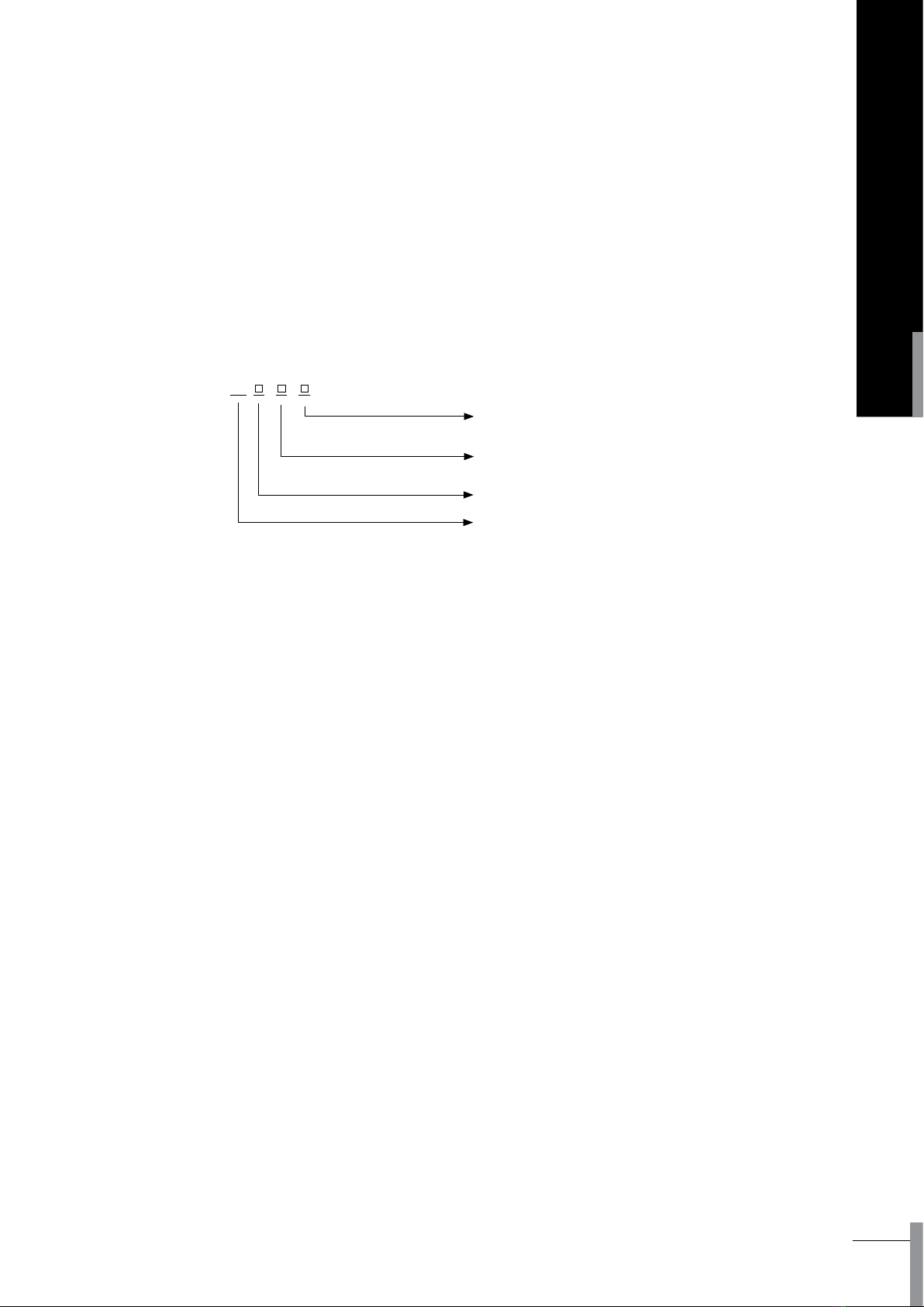
2.2 Model and implication
Note: *is capacitance increase style of 3200A shell grade, 4000A just available for 3 poles.
BA
Number of poles
(4-4 poles,3-3 poles)
Breaker grade code
(H-high breaking)
Breaker shell grade rated current value
(2000,3200,4000*,6300)
Universal circuit breaker

ACB-I
4
INSTRUCTIONS
3. Structure specications
1. Secondary circuit terminal (stationary)
2. Drawer seat
3. Safe separator plate
4. Handle
5. Secondary circuit terminal (movable)
6. Auxiliary contacts
7. Under-voltage release
8. Shunt release
9. Closing electromagnet
10. Operation mechanism
11. Intelligent controller
12. Panel
13. Motor-driven mechanism
1
2
4
3
5
6
7
8
9
10
11
12
13
ACB-I
5
AIR CIRCUIT BREAKER
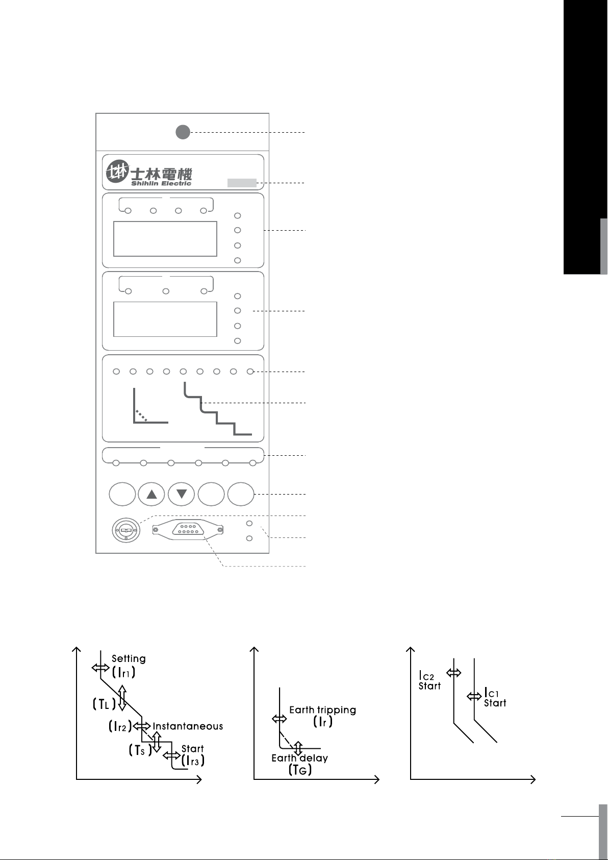
1. Mechanical reset button
2. Rated current indicator
3. Function window
4. Ammeter window
5. Protection category indicator
6. Protection characteristic curves
7. Status indicator
8. Function key
9. Position lock
10. Communication indicator
11. Programming interface
4. Intelligent controller
11
10
9
8
7
6
5
4
3
2
1
返回確認
功能
TISL
If
δ
Ic2Ic1 N
S
A/KA
%
V
KW
Hz
L3L1 L2
I
32
V
1N
COSθ
10×
儲存警報故障
狀態
試驗查詢設置
KST45-2H
In= 2000A
STATE
SET SEARCH TEST FAULT ALARM MEMORY
REMOTE
SEETING
FUNCTION ENTER RESET
PROGRAM
TxD
RxD
LOCAL

ACB-I
6
INSTRUCTIONS
Power distribution or
motor protection
Setting current value
Ir1=In×…0.4 ∼1+OFF (Exit)
Operating characteristic ≤ 1.05 Ir1 : >2h no tripping
> 1.30 Ir1 :<1h tripping
Inverse time delay
setting value tL(s)
(corresponding to 2lr1)
Characteristic curve Curve 1 ∼Curve 6* (settable)
Factory default set curve 3
Curve rate IEC60255 standard, total 96 intervals, settable
Precision ±10% (Fixed 40ms)
Generator protection
Setting current value
Ir1=In×…0.4 ∼1.25 +OFF (Exit)
Operating characteristic ≤ 1.05 Ir1 : >2h no tripping
> 1.20 Ir1 :<1h tripping
Inverse time-delay
setting value tL(s)
(corresponding to 2lr1)
Characteristic curve Curve 1 ∼Curve 6* (settable)
Factory default curve 3
Curve rate IEC60255 standard, total 96 intervals, settable
Precision ±10%
N-phase protection Setting coecient* 100% or 50% (supple to 3P+N or 4P)
Operating characteristic The same protection features as A, B, C three-phase
Thermal memory (30min, clean out while power o)Standard+OFF
Note : The setting coecient of N-phase protection is 50%, then the setting value of N-phase protection becomes 50% of
total A, B, C 3-phase. Take setting current value of long time delay as 1600A as a sample, for N-phase, its value is 800A.
4.1 Intelligent controller function
4.1.1 Protection features
4.1.1.1 Overload long time-delay trip protection features
Table 1 for reference of technical parameters of overload long time-delay protection features
Table 1: Technical parameters of overload long time-delay protection features

ACB-I
7
AIR CIRCUIT BREAKER
Short time protection has two modes:
1. Inverse time protection: when the fault current exceeds setting current value of denite time, if it is curve(1 ∼5),
controller protects according to the curve (1 ∼5) of overload long time delay, but the speed 10 times of it. (In
other words, it equals to the tenth of the delay tripping time, which computed from the overload long time curve
expression.) If it curve6, then calculate the inverse time delay tripping time from the expression of short-circuit
shot time delay curve 6 characteristic.
2. Denite time protection: when the fault current exceeds denite time current setting value, controller protects as
denite time delay setting value.
Note : If setting current value of inverse time sets on the position of "OFF" or if denite time setting current value
is less than or equal to inverse time setting current value, then controller protects according to denite
time protection, and the inverse time trip automatic avoidance. If denite time works, tripping time of the
short time delay is greater than or equal to setting value of denite time delay, no matter denite time or
inverse time. Else, denite time exits, delay tripping time of inverse time protection would not restrict by
denite time delay setting value.
Current setting value of inverse time and
denite time
Ir2=Ir1×…1.5 ∼15 +OFF (Exit)
Operating characteristic ≤ 0.9 Ir2 : no tripping
>1.1 Ir2 : delay tripping
Setting value of denite time delay: ts ts (s) 0.1 ∼1( 0.1 interval)
Precision ±10%
Inverse time protection feature 1∼5 curves are the same overload long time delay, but curve speed is 10 times.
Curve 6 characteristic express: Ts=64ts/ N2 that is Ts=ts x (8lr1/l)2
Inverse time thermal memory
(15 min, clean out when power o) Standard+ OFF
4.1.1.2 Short-circuit short time-delay protection features
Table 2 for reference of technical parameters of Short-circuit short time-delay protection features
Table 2: Technical parameters of Short-circuit short time-delay protection features

ACB-I
8
INSTRUCTIONS
4.1.1.3 Short circuit instantaneous protection features
Table 3: Technical parameters of short circuit instantaneous protection features
Setting current value
Ir3 1.0 In~50kA/75kA/100kA +OFF (EXIT)
Operating characteristic ≤ 0.85 Ir3 no tripping
>1.15 Ir3 tripping
Actuation time < 100ms ( Including original break time of the circuit-breaker)
Note : If the controller is Frame I, the setting values of instantaneous protection is 1.01 ln ∼50kA +OFF. If it is Frame II, that
setting value is 1.01 ln ∼75kA +OFF. And 1.01 ln ∼100kA +OFF as Frame III.
4.1.1.4 Unsymmetrical earthing or leakage protection features
Table 4: Technical parameters of Unsymmetrical earthing or leakage protection features
Earth fault
protection
Setting current
If=In×…0.2 ∼1 +OFF(Minimum 100A, OFF means exit)
Operating Characteristics <0.8 If: no tripping
≥ 1.0 If: delay tripping
Time delay(s)
Denite time-delayTG(s) 0.1 ∼1 +OFF
(0.1 interval, OFF means alarming without tripping)
Inverse time coecient KG1.5 ∼6 +OFF ( 0.5 interval, OFF means earthing as
denite time mode)
Precision ±10%
Leakage protection
Setting current
If=I △x …0.1 ∼1.0+OFF(0.01A interval, OFF means exit)
Operating characteristics <0.8 If: no tripping
≥ 1.0 If: delay tripping
Time delays(s)
Denite time-delayTG(s) 0.1 ∼1 +OFF(0.1 interval, OFF means alarming
without tripping)
Inverse time coecient KG1.5 ∼6 +OFF(0.5 interval, OFF means earthing as
denite time mode)
Precision ±15%

ACB-I
9
AIR CIRCUIT BREAKER
It is just available one between earth fault protection and leakage protection.
There are two styles of above two protections:
1. Inverse time protection: TG=tGx KGx If / I
In the expression: TGdenes as delay actuation time of actual protection
tGdenes as setting value of denite time delay
KGdenes as coecient value of inverse time
Ifdenes as setting current value
I denes as real working current
Delay actuation time of inverse time protection could be obtained from above expression, but it is greater than or equal
to setting value of denite time delay. It is denite time protection when KG is in OFF position.
2. Denite time protection: delay actuation time of denite time protection is denite time delay setting value.
Single earthing protection is a kind of metallic protection when fault current exceeds several hundreds ampere, which
generally applied to neutral –point directly earthing system. There are two kinds of protection modes for the controller:
One is vector sum mode of internal transformer (earthing protection). The controller"s operating apply to vector sum of
the three-phase current and neutral current, according to the numbers of poles of breaker, there are three forms: 3PT, 4PT,
(3P+N) T. This mode widely used for balance overload, unbalanced overload and motor overload systems with alarming
no tripping.
Another is transformer mode of external leakage. The controller gets the output current signal from a current transformer
directly to protect. Generally, the secondary output of the transformer is 5A/1A (secondary current is 1A if primary current
of transformer is less than 400A, else is 5A). This mode has higher sensibility especially applied to protect earth fault
whose current is smaller beginning from tens of amperes. There are two methods of ground signal"s sampling. One is
rectangular transformer sampling mode (shown as follow Mode1, Model 2). Another is ring transformer sampling mode
in which the transformer"s diameter is 100MM (Mode 3 for reference)
PEN
N
PE
N
PE
PE或PEN
ZCTZCT
ZCT
N
N
PE
intelligent
controller intelligent
controller
intelligent
controller
intelligent
controller
intelligent
controller
intelligent
controller
Mode 1 External transformer
The transformer is ZCT1.
Mode 2 External transformer
The transformer is ZCT1.
Mode 3 External transformer
The transformer is ZCT100.
3PT 4PT 3P+N

ACB-I
10
INSTRUCTIONS
(1) Specication of ZCT1 transformer
Note : 1. 200-400A/1A and 600-2000A/5A are customizable.
2. ZCT1 supplies bus bar through layout for Frame I. If ZCT1 is chosen for FrameII and Frame III, then use the way of
pulling on cables.
(2) Specication of ZT100 transformer
Primary current 200A 400A
Secondary current 1A 1A
4.1.1.5 Overload supervision and control protection features
Table 5 for reference of technical parameters of short circuit instantaneous protection features
Controller is programmed output two passive signal contacts, which can charge of overload supervision and control,
they are use for alarming, break the overload circuit and keep the main system normal power supply.
User can pick one of these two supervision patterns:
Pattern 1: control overload of two –sub-circuit, controller output the signal contracts in the light of inverse time
delay respectively when the working current exceeds 1.2 lc1 or 1.2 lc2. Characteristic curve of inverse time equal to
characteristic curve of overload long time delay, meanwhile, it is settable for curve slop and setting current value.
Pattern 2: control overload of sub circuit, if the running current surpasses 1.2 lc1, signal contracts will set out to break
sub circuit over overload by controller's action, which is according to inverse time delay characteristic. Characteristic
curve of inverse time equal to characteristic curve of overload long time delay, it is settable for curve slop and setting
current value when setting value lc1> lc2. If the running currents recover after breaking sub circuit overload, the
current lower than the setting value lc2 lasting 60s, the controller sends out a signal contact again to pick up broken
overload and restore the power supply of system.
Primary current 200A 400A 600A 1000A 2000A
Secondary current 1A 1A 5A 5A 5A
Pattern 1
Setting current value
Ic1 =In×… 0.2 ∼1+OFF( min 100A, OFF means exit)
Output characteristic
≤ 1.05 Ic1 : non making
> 1.2 Ic1 : delay relay making
Inverse time delay(s)
Characteristic curve The same as overload long time delay characteristic curve
Curve rate Set separately ( setting coecient equals to overload long time delay)
Setting current value
Ic2 =In×… 0.2 ∼1+OFF( min 100A, OFF means exit)
Output characteristics
≤ 1.05 Ic2 : non making
> 1.2 Ic2 : delay relay making
Inverse time delay(s)
Characteristic curve The same as overload long time delay characteristic curve
Curve rate Set separately ( setting coecient equals to overload long time delay)
Pattern 2
Setting current
Ic1 =In×… 0.2 ∼1+OFF( min 100A, OFF means exit)
Output characteristic
≤ 1.05 Ic1 : non making
> 1.2 Ic1 : delay relay making
Inverse time delay(s)
Characteristic Curve The same as overload long time delay characteristic curve
Curve rate Set separately ( setting coecient equals to overload long time delay)
Setting current
Ic2 =In×0.2 ∼1+OFF(OFF means exit)
Output characteristic <Ic2 delay relay making
Constant time lag(s)Fixed 60s
Precision ±10%
Thermal memory( 30min, re-set while power o) Standard+OFF
Table 5: Technical parameters of short circuit instantaneous protection features

ACB-I
11
AIR CIRCUIT BREAKER
Setting value of Imbalance
current ratio
δ= 40%~100%+OFF(1% interval, OFF means exit)
Operating or alarm
characteristic
≤ 0.9δ: no tripping
>1.1δ: delay tripping
Setting value of time delay Tδ(s) 0.1~1s+OFF(OFF means alarming without tripping, 0.1 interval )
Precision ±10% 40ms
4.1.2.1 Inspection display
This function keeps all lightening devices indicating accurately in order to maintenance good working
situation. Chapter 7.2.2.3 shows the details.
4.1.2.2 Test
Tripping and non-tripping are two ways of stimulation test.
1. Stimulation test of tripping: this test is carried out by instantaneous of tripping. There will be trip and action
time of devices display, which used for cooperating with breaker to success testing tripping several times
by using the test function key after field debugging, periodic-checking and overhauling. Press the red
button on the top of the controller panel before making.
2. Stimulation test of no tripping: Checking the protection feature of the controller, there will be results of
no trip, current display in turn and delay action time under this test current. By using this test, the whole
procession of actual protection or overload monitor identify without complicated calculation of six kinds of
overload characteristic curves. Chapter 7.2.3.5 shows the details.
4.1.2.3 Historical fault recording
While faults occur, the controller will record the relative state and data. After fault-reset or power-o actions,
the controller still has fault memory that records the historical event. The old data covered when the new
occurs, so it is convenient for analysis before the new comes. Details refer to 7.2.3.2
4.1.2.4 Self-diagnosis
Light T on the panel of the controller will ash when self-diagnosis fault occurs. Details refer to 7.2.3.4.
4.1.2.5 Thermal memory
Repeating overload may cause conductor heating up. The controller has thermo-effect (which simulating
bimetallic strip"s characteristic) after delay tripping because of overload and short-time delay. The thermo-
eect energy of overload release completely in 30 minutes after the fault removed, and for short time delay,
it releases completely in 15 minutes after fault removed. The delay time will shorten if overload or short
time delay reoccurs after re-closing the breaker during this time, so that the circuit and equipment could be
protected well. (The thermal memory characteristic of overload monitoring is the same to that of overload
protection).
Accumulated thermo-effect eliminated if the controller power-off and then re-power on. This function is
defaulted to be closed when leaves factory, if necessary please point out when ordering or set through ST
programmer.
4.1.1.6 Imbalance current protection features
Table 6 for reference of technical parameters of imbalance current protection features
Unbalance current of Loss of phase and 3-phase are protected by this imbalance current protection. Here is the
expression of imbalance current ratio:
δ=| l- lav| / lav ( lav is average of 3-phase)
Imbalance current protection feature is a kind of definite time protection. The setting value of time delay use
tδmark, protection of imbalance currant with the function of alarming without tripping when tδin the OFF
position.
Table 6: Technical parameters of imbalance current protection features
4.1.2 Auxiliary functions

ACB-I
12
INSTRUCTIONS
4.1.2.6 MCR make-break and overstep tripping (optional)
Make-break and overstep tripping protections are parts of back-up functions, which are optional. They
are both instantaneous tripping actions whose tripping value relate to their service breaking and ultimate
breaking capacities. Usually, MCR current is 40KA, 60KA, 80KA, overstep tripping current is 50KA, 75KA,
100KA(especially for Type DW40,45,48 breaker, the factory defaults of current values are 40/50KA for Frame
I, 60/75KA for Frame II, 80/100KA for Frame III). Fault current signal sends out tripping instruction directly by
hardware comparison circuit. MCR make-break protection works only at the moment of making (about 100
ms), while overstep tripping is available all the time.
4.1.2.7 System clock adjustment function (optional)
The controller can be added function of system clock adjustment, to record time and date when the fault
generated. This function automatically eectiveness once is chosen. Details of the function of system clock
adjustment considering chapter7.2.3.5
4.1.2.8 Signal contact output function (optional)
The controller output 4 groups of signal separately, this function realized by programmer or other special ways.
The provided signal contacts output function and output time indicated as table 7.
Defaulted states of the controller's 4 groups signal contacts output function indicated as table 8.
Table 7 : Controller's signal contacts output function and output time
Serial number Signal contact output function Signal contact output time
0 No denition No output
1 Trip and alarm if short circuit fault instantaneous fault Output when short circuit instantaneous fault trip
occurs
2 Trip and alarm if earthling or leakage fault Outputting when grounding or leakage fault trip occurs
3 Trip and alarm if unbalance current fault Outputting when unbalanced current fault trip occurs
4 Trip and alarm if short circuit short time delay fault Outputting when short circuit short delay
fault trip occurs
5 Trip and alarm if overload long time delay fault Outputting when overload long delay fault trip occurs
6 Trip and alarm if fault Outputting when any fault trip occurs
7 Unoverload output if overload monitor 1 Outputting when overload monitor 1 time over
8 Unoverload output if overload monitor 2 Outputting when overload monitor 2 time over
9 Alarm if system self-diagnose Outputting when system self-diagnose fault occurs
10(A) Alarm if power grid in fault state Outputting at beginning of protection or
monitor delay operation
Table 8 : Defaulted function states of 4 group's contacts in controller
Note : Contact 3 and contact 4 for Type 2H controller are xed just for remote break and remote make
Contact number
Controller type
Contact 1 Contact 2 Contact 3 Contact 4
Type2M Overload monitor 1
unoverloadoutput
Overload monitor 2
unoverload output
system
self-diagnose fault
alarming
fault tripping and
alarming
Type2H Overload monitor 1
unoverload output
Overload monitor 2
unoverload output Remote breaking Remote making
Contact number
Controller type
ACB-I
13
AIR CIRCUIT BREAKER
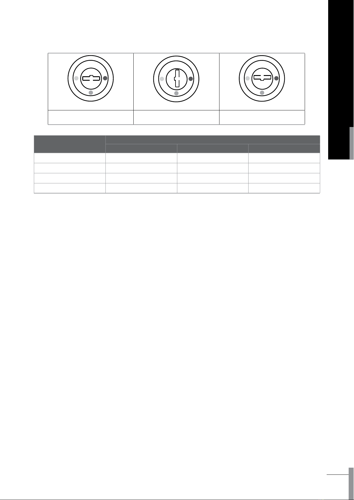
LOCAL LOCAL LOCAL
REMOTE LOCAL SET
REMOTE
Operation type Status of position lock
SET LOCAL REMOTE
Remote control Not Available Not Available Available
Local parameter set Available Not Available Not Available
Local test Available Not Available Not Available
Programmer operation Available Available Available
4.1.2.9 Position lock
There are three position locks: "SET", "LOCAL", "REMOTE" on the panel of the controller for Type KST-2H.
4.1.2.10 Programming interface function
The controller provides programming interface to communicate with programmer. Users can set internal
parameters by programmer, such as: choose type of overload protection characteristic curve, turn on or turn
o thermal memory function, set signal contact output function, choose communication protocol function,
set communication address, choose communication baud rate, set system clock, set function lock and unlock,
choose connection mode of voltage etc. The programmer also has break/close test function, historical data
review function, set value copy and other functions.
The telecommunication of the controller stops automatically when the programmer connected to the
interface, after the programmer pull out, the telecommunication resumes automatically.
Apply for "ST programmer operating instruction" to get more information.
4.1.2.11 Analogy calculation function of main contact rate of wear
The controller can simulated calculate the main contact wear rate according to the fault current and other
data when breaking. The factory-set is 100%; it shows no wear on the main contact. After each breaking
operation, the controller will deduct corresponding wear rate, when the value ≤ 60%, system will set alarm
the self-diagnose signal to inform users taking the maintenance action in time.
After replacing the main contact, users can reset the initial wear rate as 100% by programmer or other special
ways.
4.1.2.12 Historical data recording (optional)
The controller can note various historical data of the power grid every 30 minutes, includes date, time,
current, voltage, power, frequency, power factor, kilowatt-hour, lasting 3 months. Via programmer interface
or telecommunication interface, the relative data review software. In the computer can be read out the
information.
ACB-I
14
INSTRUCTIONS
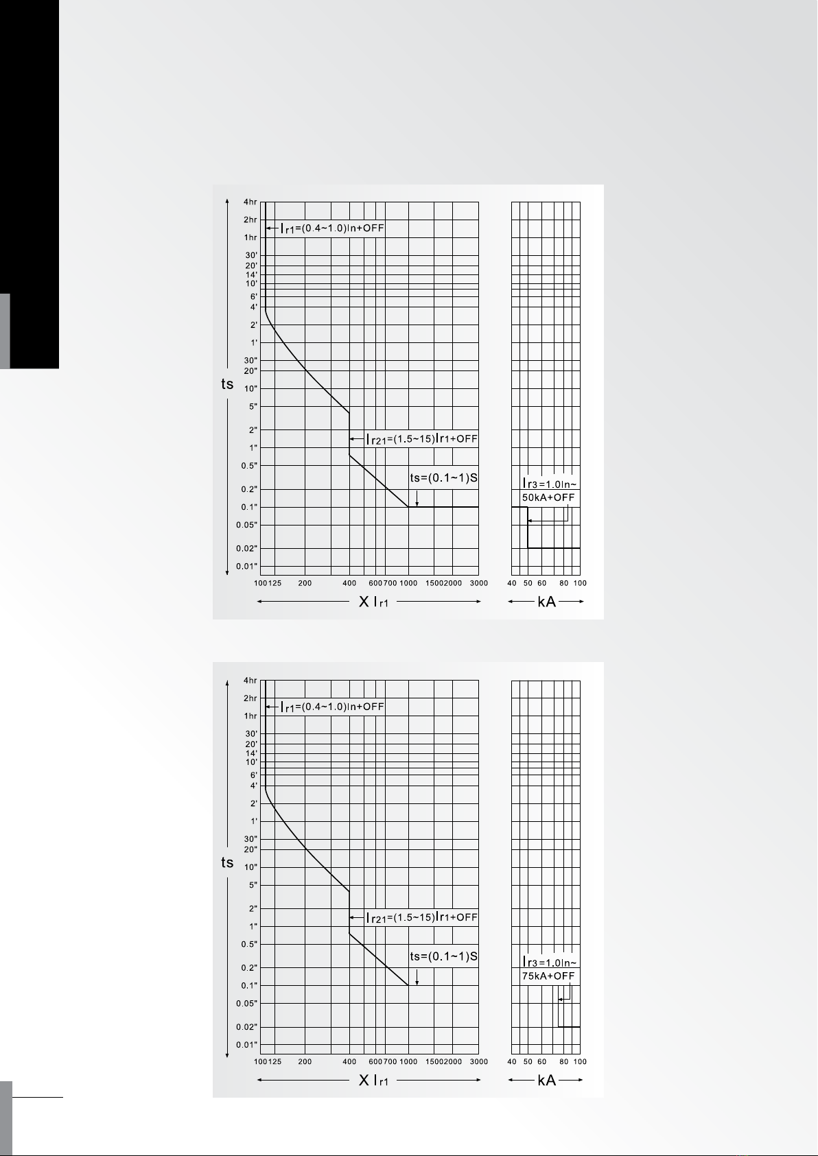
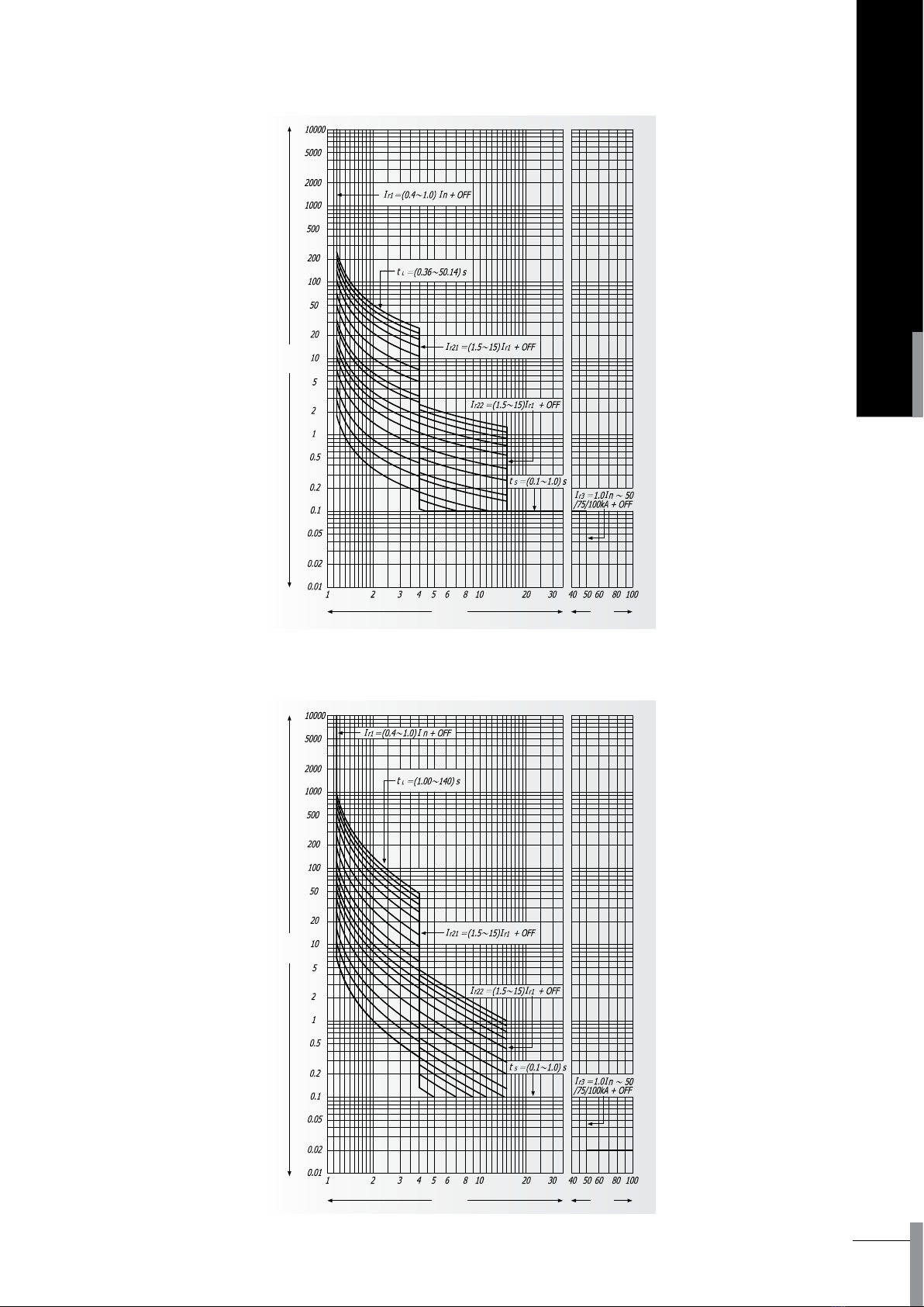
5.1 ACB Operating curves
5.1.1 BA2000-H
5.1.2 BA3200-H
5. Time/Current curve

ACB-I
15
AIR CIRCUIT BREAKER
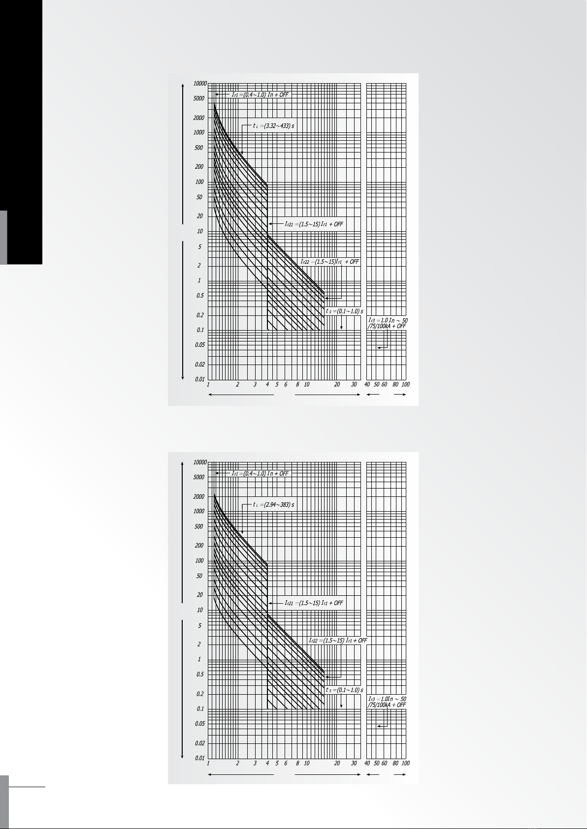
5.1.3 BA4000-H, BA5000-H, BA6300-H

ACB-I
16
INSTRUCTIONS
Controller oers six kinds of characteristic curve of overload protection, following the expression:
1. Standard inverse time: T=0.01396t/ (N0.02-1)
2. Quick inverse time: T=t/ (N-1)
3. Super inverse time (general purpose): T=3t (N2-1)
4. Super inverse time (motor protection): T=2.95 t x In [N2/ (N2-1.15)]
5. High-voltage fuse compatibility: T=15t/ (N4-1)
6. Super inverse time 2(general purpose): T=2.25 t/ N2
Equal to T=t x (1.5 lr1/ l) 2
Serial
No.
Inverse time delay setting value of overload protection characteristic curve: t (s)
Delay trip time corresponding to 2lr1
Delay trip time
corresponding to
1.5lr1
Standard inverse
time curve 1
Quick inverse time
curve 2
Super inverse time
(general purpose)
curve 3
Super inverse time
(motor protection)
curve 4
High-voltage fuse
compatibility
curve 5
Super inverse
time 2 (general
purpose) curve 6
10.36 1.00 3.32 2.94 0.66 15
2 0.58 1.60 5.32 4.72 1.06 20
3 0.86 2.40 8.00 7.06 1.60 25
4 1.42 4.00 13.32 11.78 2.66 30
5 2.14 6.00 20.00 17.68 4.00 40
6 2.86 8.00 26.66 23.58 5.32 50
7 3.58 10.00 33.32 29.46 6.66 60
8 5.36 13.50 45.00 39.78 9.00 80
9 6.44 18.00 60.00 53.04 12.00 100
10 10.02 28.00 93.32 82.52 18.66 120
11 14.32 40.00 133 117 26.66 160
12 21.48 60.00 200 176 40.00 200
13 28.64 80.00 266 235 53.32 240
14 35.80 100 333 294 66.66 320
15 42.98 120 400 353 80.00 400
16 50.14 140 433 383 86.66 480
Calculate illustration:
Assume the setting conditions of a controller as, Curve 3 is the characteristic curve of overload long time delay
protection, lr1, tl are 2000A and 20.00s respectively. Calculate the time of overload long time delay TL when the actual
fault current is 3000A.
N=l/lr1=3000/2000=1.5
TL=3 Tl/ ( N2-1) =3 x 20/ (1.5×1.5-1) =48s
Therefore, here TL is 48s.
Table 9: 6 kinds of inverse time delay setting value of overload protection characteristic curve
Moreover,
T is time value of actual protection delay.
t is setting value of inverse time delay, all setting values of inverse time delay shown in Table 3.
N=l/lr1, it is ratio of actual working current to setting current value of overload long time delay.
5.2 Controller (IEC 60255 standard)
5.2.1 Overload protection curve
ACB-I
17
AIR CIRCUIT BREAKER
T(s)
Xl r1 kA
T(s)
Xl r1 kA
5.2.1.1 Standard inverse time : T=0.01396t/(N0.02-1)
5.2.1.2 Quick inverse time : T = t / (N-1)
ACB-I
18
INSTRUCTIONS
T(s)
T(s)
Xl r1 kA
Xl r1 kA
5.2.1.3 Super inverse time (general purpose) : T=3t / (N2- 1 )
5.2.1.4 Super inverse time (motor protection) : T=2.95t×In (N2/(N2-1.15))
This manual suits for next models
5
Table of contents
Other Shihlin electric Circuit Breaker manuals


