dolycon CT100G Series User manual

CT100G Series Inverter Safety precautions
- 3 -
»Keep the signal cables of the inverter away from the power cables as far as
possible, or distribute the two categories of cables vertically-crossed if the
distance is not far enough, otherwise it may cause signal interference.
» Ensure that all the screws are tightened when wiring, otherwise damage to
the inverter may occur.
» The encoders and sensors should be applied with the shielded cables and
the shielded layer should be grounded reliably.
Operation
» Confirm that the wiring is completed and correct and then cover the plate
before power on.
» Do not open the plate after power on, otherwise electric shock may occur.
» Operate the inverter appropriately, otherwise damage to the inverter may
occur.
» Non-professionals are not allowed to test the signals when the inverter is
running. Otherwise, physical injury or damage to the devices may occur.
» Do not change the parameters of the inverter at random, otherwise damage
to the inverter may occur.
» Do not touch the fans and brake resistors, otherwise it may cause
mechanical injury or burn.
» Do not start up or stop the inverter by power on or off, otherwise damage to
the inverter may occur.
» Ensure that the circuit breakers or contactors at the output sides of the
inverter are not in output state before switching, otherwise damage to the
inverter may occur.

CT100G Series Inverter Safety precautions
- 4 -
Others
» This inverter is not suitable for the occasions when the specifications exceed
those specified in this manual. If you have special requirements, please
contact our technical department.
» The inverter is equipped with surge suppressors inside, which can protect it
from the lightning. It is necessary to mount external surge suppressors at the
power input side of the inverter in high lightning incidence areas.
» When the conductors between the inverter and the motor exceed 100m, it is
recommended to mount the output reactors to avoid overcurrent caused by
excessive distributed capacitance.
» Do not mount the compensation capacitors and the surge absorbers at the
output sides of the inverter. Otherwise, it may cause damage to the inverter
due to overheating.
» Mounting the input or output reactors, special filters and magnetic rings at
the input or output sides of the inverter can effectively reduce the noise and
thus avoid interference to other devices.
» Non-professionals are not allowed to perform withstand voltage tests on the
inverter, , otherwise damage to the inverter may occur.
» Deal with the devices as industrial effluent after scrapping. Burning is strictly
prohibited, otherwise an explosion may occur.
» The cooling effect of the inverter is reduced and the electrolytic capacitor
electrolyte is also volatile in high altitude areas, which will shorten the life of
the inverter. Check the altitude of the actual usage site is below 1000m. If
higher than 1000m, reduce 1% for every additional 100m.

CT100G Series Inverter CHAPTER 1 PRODUCT INFORMATION
- 5 -
CHAPTER 1 PRODUCT INFORMATION
1.1 Product model name rules
The letters and numbers of the type designation key indicate product
series, voltage, power, load etc.
Figure 1-1 Type designation key
1.2 Product specifications and technical parameters
1.2.1 Product specifications
Table 1-1 Product Specifications
Inverter mode Power
(KW)
Input
current
(A)
Output
current
(A)
Applicable
motor power
(KW)
Single phase 220V 50/60Hz
CT100G-2S-0.7G-B 0.75 8.2 4.5 0.75
CT100G-2S-1.5G-B 1.5 14.0 7.0 1.5
CT100G-2S-2.2G-B 2.2 23.0 9.6 2.2
CT100G-2S-4.0G-B 4.0 36.0 16.0 4.0
CT100G-2S-5.5G-B 5.5 46.0 20.0 5.5
CT100G-2S-7.5G-B 7.5 68.0 30.0 7.5
Three phase 380V 50/60Hz
CT100G-4T-0.7G-B 0.75 3.4 2.5 0.75
CT100G-4T-1.5G-B 1.5 5.0 3.7 1.5
CT100G-4T-2.2G-B 2.2 5.8 5.3 2.2
CT100G-4T-4.0G-B 4.0 12.0 9.5 4.0

CT100G Series Inverter CHAPTER 1 PRODUCT INFORMATION
- 6 -
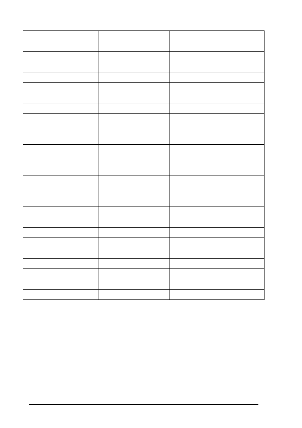
CT100G-4T-5.5G-B 5.5 18.5 14 5.5
CT100G-4T-7.5G-B 7.5 22.5 18.5 7.5
CT100G-4T-11G-B 11 30.0 25.0 11
CT100G-4T-15G-B 15 39.0 32.0 15
CT100G-4T-18.5G-B 18.5 45.0 38.0 18.5
CT100G-4T-22G-B 22 54.0 45.0 22
CT100G-4T-30G-B 30 68.0 60.0 30
CT100G-4T-37G 37 84.0 75.0 37
CT100G-4T-45G 45 98.0 92.0 45
CT100G-4T-55G 55 123.0 115.0 55
CT100G-4T-75G 75 157.0 150.0 75
CT100G-4T-90G 90 188.0 180.0 90
CT100G-4T-110G 110 221.0 215.0 110
CT100G-4T-132G 132 267.0 260.0 132
CT100G-4T-160G 160 309.0 305.0 160
CT100G-4T-185G 185 344.0 340.0 185
CT100G-4T-200G 200 384.0 380.0 200
CT100G-4T-220G 220 429.0 425.0 220
CT100G-4T-250G 250 484.0 480.0 250
CT100G-4T-280G 280 539.0 530.0 280
CT100G-4T-315G 315 612.0 600.0 315
CT100G-4T-355G 355 665.0 650.0 355
CT100G-4T-450G 450 805 795.0 450
CT100G-4T-500G 500 890 860.0 500
CT100G-4T-560G 560 1045 1015 560
CT100G-4T-630G 630 1224 1200 630
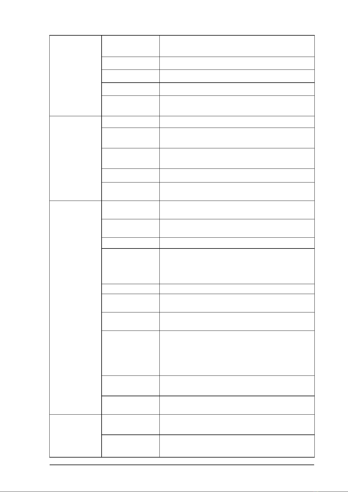
Note: 1. The inverters with power less than or equal to CT100G-4T-160G are
equipped with braking units, but 37-160kw models are optional with or without
braking units. And braking resistors inside whose power and resistance are as
required as the table 2-2, otherwise has risk of damage. CT100G-4T-185G and
bigger power models can be equipped with external braking units bought by
customers themselves.
2. The above models are the standard general purpose inverters, excluding the
industrial special inverters. You can customize non-standard inverters of other
specifications.
1.2.2 Technical parameters
Table 1-2 Technical parameters

CT100G Series Inverter CHAPTER 1 PRODUCT INFORMATION
- 7 -
Input and
output
parameters
Input voltage Single-phase 220VAC±15%
Three-phase 380VAC±15%
Input frequency 50~60Hz±5%
Output voltage 0~Rated input voltage
Output frequency 0~500Hz, unit 0.01Hz
Overload
capacity
150% of rated current: 60s; 180% of rated
current: 10s; 200% of rated current: 1s
Running
control
parameters
Control mode V/F control, sensorless vector control (SVC)
Adjustable-speed
ratio 1:100 (V/F); 1:200 (SVC)
Speed control
accuracy ±0.5%
Speed wave ± 0.5%
Start torque 0.5Hz/150% (V/F)
0.25Hz/150% (SVC)
Based
functions
Starting
frequency 0.00~10.00Hz
ACC and DEC
time 0.1~65000.0s
Carrier frequency0.5KHz~16.0KHz
Frequency
setting
UP/DOW setting,analog setting, digital setting,
multi-step speed setting, PID setting,
MODBUS communication setting, to realize
switch of combination and channel setting.
Start mode Start frequency, DC braking and start
Stop mode DEC stop, free stop, DEC
+DC braking
Energy braking
capability Braking unit braking voltage:320~750V
DC braking
capability
DC braking frequency: 0~500Hz;
DC braking waiting time: 0~10s;
DC braking current: 0.0~100.0%;
DC braking time: 0.0~100.0s;
Auto voltage
adjustment
Keep a stable voltage automatically when the
grid voltage transients
Sudden
frequency down
Keep stable bus voltage while power net
low-voltage
Control
terminals
Digital input Standard 8-channel inputs, one of which can
be high-speed pulse input (HDI)
Analog input Standard 2-channel inputs, AI1: 0~10V or
0/4~20mA input optional, AI2:0V0~+10V

CT100G Series Inverter CHAPTER 1 PRODUCT INFORMATION
- 8 -
Digital output
Standard 2-channel multi-function collector
outputs, one of which can be high-speed pulse
output (HDO).
Relay output Standard 2-channel relay outputs
Communication
interface
RS485
Communication
RS485 communication interface for external
communication, support Modbus protocol
(RTU mode).
Fault protection
ACC overcurrent, DEC overcurrent, constant speed overcurrent,
ACC overvoltage, DEC overvoltage, constant speed overvoltage,
bus under voltage, motor overload, inverter overload, input
power failure, output phase loss, rectifier module overheating,
inverter module overheating, external fault, communication fault,
current detection fault, EEPROM operation fault, PID feedback
fault, factory setting time arrive etc.
Keypad display LED display Highlight LED digital tube displays the inverter
information
Others
Running
environment
Indoors, less than 1km above sea level,
without dust, corrosive gases or direct sunlight
Ambient
temperature
-10~+40℃, derate 1% for every additional 1℃
when the ambient temperature is between
40~50℃
Humidity 5~95% (no condensation)
Altitude 0~2000m, derate 1% for every additional
100m when the sea level is above 1000m
Vibration Less than 0.5g
Storage
temperature −40~+70℃
Control
terminals Digital input Standard 8-channel inputs, one of which can
be high-speed pulse input (HDI)
1.3 Product outline and installation size, weight

CT100G Series Inverter CHAPTER 1 PRODUCT INFORMATION
- 9 -
a) C0 models
b) C1,C2 models
c) C3~C6 models

CT100G Series Inverter CHAPTER 1 PRODUCT INFORMATION
- 10 -
d) C7,C8 models
e) C11,C12 models
Figure 1-2 Product appearance and installation dimensions diagram
Table 1-3 Structure, mounting dimension and weight

CT100G Series Inverter CHAPTER 1 PRODUCT INFORMATION
- 11 -
Inverter mode Appearance and dimensions(mm)Installing
hole(mm) weight cabinet
W H D W1 H1 H2
CT100G-2S-0.7G-B
126 186 155 115 175 --- 5 1.6 C0
CT100G-2S-1.5G-B
CT100G-2S-2.2G-B
CT100G-4T-0.7G-B
CT100G-4T-1.5G-B
CT100G-4T-2.2G-B
CT100G-4T-4.0G-B
CT100G-4T-5.5G-B
CT100G-4T-7.5G-B 140 230 172 128 218 --- 5.5 3.5 C1
CT100G-4T-11G-B 165 285 200 153 273 --- 5.5 5.2 C2
CT100G-4T-15G-B
CT100G-4T-18.5G-B
214 402 205 184 360 385 7 11.5 C3CT100G-4T-22G-B
CT100G-4T-30G-B
CT100G-4T-37G 250 442 230 220 405 425 7 19 C4
CT100G-4T-45G
CT100G-4T-55G
299 602 276 240 540 580 9 30 C5
CT100G-4T-75G
CT100G-4T-90G
CT100G-4T-110G
CT100G-4T-132G 329 660 332 250 601 640 9 56 C6
CT100G-4T-160G
CT100G-4T-185G
480 853 354 180 772 826 11 110 C7
CT100G-4T-200G
CT100G-4T-220G
CT100G-4T-250G
CT100G-4T-280G
CT100G-4T-315G
680 940 370 290 908 --- 13 165 C8CT100G-4T-355G
CT100G-4T-400G
CT100G-4T-450G 880 962 370 170 928 180 13 200 C11
CT100G-4T-500G
CT100G-4T-560G 950 962 380 314 923 --- 13 220 C12
CT100G-4T-630G

CT100G Series Inverter CHAPTER 1 PRODUCT INFORMATION
- 12 -
1.4 Outline and size of keypad
Figure 1-3 Structure diagram of the keypad (unit: mm)
Figure 1-4 Structure diagram of the outer bracket (unit: mm)
Note: while use external keypad, the wire should not be more than 30m, otherwise there is
risk of keypad not work.

CT100G Series Inverter CHAPTER 2 INSTALLATION AND WIRING
- 13 -
CHAPTER 2 INSTALLATION AND WIRING
2.1 Installation environment
1. Ambient temperature: -10℃~+40℃, derate to use if the temperature is above
40℃
2. Relative humidity: ≤ 95%, no condensation
3. Vibration: <0.5g
4. The inverter should be installed on the flame-retardant materials and there is
enough space for heat dissipation.
5. The inverter can output the rated power when the altitude is below 1000m. If
the altitude is above 1000m, the output power will decrease. It is recommended
to derate 1% for every additional 100m.
6. The inverter is not allowed to fall to the ground suddenly.
7. The inverter is not allowed to be installed near the electromagnetic radiation
sources.
8. The inverter is not allowed to be installed in the atmospheres with flammable,
explosive or corrosive gases.
9. The inverter is not allowed to be installed in the environments with direct
sunlight, oil mist or steam.
10. Avoid screws, cables, drilling debris and other conductive matters falling into
the inverter during installation, otherwise it may cause the inverter failure.
11. For the bad installation environments (like textile industry), it is recommended
to install the radiator outside the cabinet.
2.2 Installation and disassembly of the keypad and the cover plate
2.2.1 Functions of peripheral components
Table 2-1 Functions of peripheral components
Name Functions
Circuit breaker
Cut off the power and protect the latter when the latter devices
have failure.
Select the circuit breaker of the breaking current by 2 times of
the inverter.
Leakage
protector
PWM high frequency chopper voltage output causes high
frequency leakage current, so select a special leakage
protector.
Contactor
Frequent switching on-off the contactor causes inverter failure,
so do not start or stop the inverter by switching on-off the main
circuit, which will affect the life of the inverter.
Input reactor
and DC
reactor
Improve the input power factor;
Reduce the impact on the system caused by the unbalance of
input power;
Suppress high harmonics and reduce external conduction;
Suppress the interference on the rectifier bridge caused by the
pulse current.
Input and
output filters Reduce the interference of the inverter on peripheral devices.
Braking
unit
Consume
the
feedback
energy
from
motors
and
brake
rapidly

CT100G Series Inverter CHAPTER 2 INSTALLATION AND WIRING
- 14 -
and braking
resistor
during braking.
Output reactor
Reduce the protection of the inverter due to leakage current;
When the cable connecting the inverter and the motor is more
than 100m, it is recommended to install the output reactor.
2.2.2 Standard configuration of peripheral components
Figure 2-1 Standard peripheral components

CT100G Series Inverter CHAPTER 2 INSTALLATION AND WIRING
- 15 -
2.2.3 Specifications of cables, circuit breakers and contactors
Table 2-2 Specifications of the cables, the circuit breakers and the contactors
Inverter mode Cables
(m2)
Circuit
breaker
(A)
contacto
r(A)
Braking
units&resistors
Power
(KW)Resist(Ω)
CT100G-2S-0.7G-B 2.5 16 10 ≧0.3 ≧200
CT100G-2S-1.5G-B 4 20 16 ≧0.3 ≧150
CT100G-2S-2.2G-B 4 32 25 ≧0.3 ≧85
CT100G-4T-0.7G-B 2.5 10 10 ≧0.3 ≧320
CT100G-4T-1.5G-B 2.5 16 10 ≧0.3 ≧250
CT100G-4T-2.2G-B 2.5 16 10 ≧0.3 ≧150
CT100G-4T-4.0G-B 4 25 16 ≧0.75 ≧85
CT100G-4T-5.5G-B 4 32 25 ≧1≧58
CT100G-4T-7.5G-B 4 40 32 ≧1.3 ≧43
CT100G-4T-11G-B 4 63 40 ≧1.8 ≧32
CT100G-4T-15G-B 6 63 40 ≧2.5 ≧25
CT100G-4T-18.5G-B 6 100 65 ≧3≧20
CT100G-4T-22G-B 10 100 65 ≧5≧17.5
CT100G-4T-30G-B 16 125 80 ≧6≧13
CT100G-4T-37G-B 16 160 80 ≧7.5 ≧10
CT100G-4T-45G-B 25 200 95 ≧8.5 ≧8
CT100G-4T-55G-B 35 200 125 ≧12 ≧7
CT100G-4T-75G-B 50 250 160 ≧14 ≧5.3
CT100G-4T-90G-B 70 250 160 ≧16 ≧4.5
CT100G-4T-110G-B 95 350 350 ≧21 ≧3.7
CT100G-4T-132G-B 150 400 400 ≧26 ≧3.3
CT100G-4T-160G-B 185 500 400 ≧31 ≧3.0
CT100G-4T-185G
240 630 400
External braking units
and resistors are
chosen according to
braking units.
CT100G-4T-200G 150*2 630 630
CT100G-4T-220G 150*2 630 630
CT100G-4T-250G 185*2 800 630
CT100G-4T-285G
150*3 800 800
CT100G-4T-315G 150*3 800 800
CT100G-4T-355G 150*3 1280 960
CT100G-4T-400G
150*4 1380 1035
CT100G-4T-450G 150*4 1580 1185
CT100G-4T-500G 150*4 1720 1290
CT100G-4T-560G
185*4 2030 1525

CT100G Series Inverter CHAPTER 2 INSTALLATION AND WIRING
- 16 -
Inverter mode Cables
(m2)
Circuit
breaker
(A)
contacto
r(A)
Braking
units&resistors
Power
(KW)Resist(Ω)
CT100G-4T-630G 240*4 2400 1800
Note: When the inverter is built-in with braking units, the power and resistance of
the braking resistors should be as required above the table, otherwise the
damage to the inverter may occur. Braking resistors are mounted externally, you
need to purchase yourselves.
2.3 Main electric loop terminal
2.3.1 Functions of the main circuit terminals
Table 2-3 Functions of the main circuit terminals
Terminals Function
R, S, T Three-phase power input terminals
(+), (-) Reserved terminals for external braking
units, common DC bus terminals
(+), PB Reserved terminals for external braking
resistors
P1, (+) Reserved terminals for external DC
reactors
(-) DC negative bus output terminal
U, V, W Three-phase AC output terminals
Grounding terminal (PE)
2.3.2 Standard wiring diagram

CT100G Series Inverter CHAPTER 2 INSTALLATION AND WIRING
- 17 -
Figure 2-2 Standard wiring diagram
2.4 Control circuit connection
2.4.1Precautions
Please apply the multi-core shielded cable or twisted pair to connect the control
terminals. When using the shielded cable (near one side of the inverter), connect
it to the PE terminal of the inverter. Keep the control cable away from the main
circuit and strong power circuit (including power cables, motor cables, relays,
contactors, etc.) more than 20cm. Vertical wiring is recommended instead of
parallel wiring to prevent the inverter malfunction caused by external
interference.
2.4.2Schematic diagram of the control plate

CT100G Series Inverter CHAPTER 2 INSTALLATION AND WIRING
- 18 -
Figure 2-3 Schematic diagram of the control plate
2.4.3 Pins of the control plate
Table 2-4 Pin instructions of the control plate
No. Instructions
X1 RS485 terminating resistor setting

CT100G Series Inverter CHAPTER 2 INSTALLATION AND WIRING
- 19 -
Short circuit the pins 1 and 2 of X1 by short-circuit module,
the terminating resistor of 120Ωis used for RS485 bus;
Short circuit the pins 2 and 3 of X1 by short-circuit module,
the terminating resistor is not used for RS485 bus;
When the short-circuit module is not used, the terminating
resistor is not used for RS485 bus.
X2
Analog input 1 voltage and current selection
Short circuit the pins 1 and 2 of X2 by short-circuit module, the
analog input 1 is voltage input (0~10V);
Short circuit the pins 2 and 3 of X2 by short-circuit module, the
analog input 1 is current input (0~20mA);
When the short-circuit module is not used, the analog input 1 is
voltage input (0~10V).
X3
Analog
output
1
voltage
and
current
selection
Short circuit the pins 1 and 2 of X3 by short-circuit module, the
analog output 1 is voltage output (0~10V);
Short circuit the pins 2 and 3 of X3 by short-circuit module, the
analog output 1 is current output (0~20mA).
X4
Analog
output
2
voltage
current
selection
Short circuit the pins 1 and 2 of X4 by short-circuit module, the
analog output 2 is voltage output (0~10V);
Short circuit the pins 2 and 3 of X4 by short-circuit module, the
analog output 2 is current output (0~20mA).
X1
3
Short circuit the pins 1 and 2 of X13 by short-circuit module, the
terminal +10V/5V supplies power +10V;
Short circuit the pins 2 and 3 of X13 by short-circuit module, the
terminal +10V/5V supplies power +5V.
X6
Special pins for control board CPU downloading (factory set, unnecessary
to change)
X7
X8
X9 The interface of the main signal for connecting the signals between the
control board and the power board
2.4.4 Terminals of control circuit

CT100G Series Inverter CHAPTER 2 INSTALLATION AND WIRING
- 20 -
Figure 2-5 control board terminal ports
Figure 2-6 control board terminal label
2.4.5 Functions of the main circuit terminals
Table 2-5 Functions of the control board terminals
Categor
y
Terminal
name Terminal function Technical specification
Switch
input
+24V +24V power supply 24V±10%, internal isolation from
GND. Max. load 200mA
PW
External power input
terminal (power
supply of digital
input terminal)
Short circuit with +24V by
default
DI1~DI7 Switch input
terminals 1~7Input specifications: 24V, 5mA
HDI High speed pulse
input or switch input
Pulse input frequency range:
0~50kHz
High level voltage: 24V
COM
+24V power supply
or external power
ground
Internal isolation from GND
Switch
output
DO
Open collector
output, common
CME terminal
External voltage range: 0~24V
CME
Common terminal of
open collector
output
Short circuit with COM by
default
HDO
High speed pulse
output or open
collector output,
common COM
terminal
Pulse output frequency range:
0~50kHz
COM HDO common
terminal Internal isolation from GND
Analog +10/5V The local supplies Output voltage: 10V or 5V

CT100G Series Inverter CHAPTER 2 INSTALLATION AND WIRING
- 21 -
input +10V or 5V power
output
available via X13, optional
Output current range: 0~50mA
(If the potentiometer is
connected between +10V/+5V
and GND, the resistance should
not be less than 2kΩ.)
AI1 Analog input
terminal 1
Input voltage and current are
optional
Input voltage range: 0~10V
Input current range: 0/4~20mA
AI2 Analog input
terminal 2 Input voltage range: 0~10V
GND Analog ground Internal isolation from COM
Analog
output
AO1~AO2 Analog output
terminal
Output voltage and current are
optional
Output voltage range: 0~10V
Output current range: 0/4~
20mA
GND Analog ground Internal isolation from COM
Relay
output
T1A/TIB/TIC Relay output
T1A-T1B: normally closed
T1A-T1C: normally open
Contact capacity: 250VAC/3A,
30VDC/1A
T2A/T2B/T2
CRelay output
T2A-T2B: normally closed
T2A-T2C: normally open
Contact capacity: 250VAC/3A,
30VDC/1A
Commun
ication
interface
485+/485-
RS485
communication
interface
RS485 communication interface
2.4.6 Wiring of switch inputs
By using the internal +24V power supply of the inverter, the wiring of the external
controller for the NPN type sink current is as shown below:

CT100G Series Inverter CHAPTER 2 INSTALLATION AND WIRING
- 22 -
Figure 2-7 Wiring of NPN type sink current
By using the internal +24V power supply of the inverter, the wiring of the external
controller for the PN type source current is as shown below:
Figure 2-8 Wiring of PNP type source current
Note: Be sure to remove the short-circuit plate between +24V and PW and
connect the plate between PW and COM.
By using the external power supply, the wiring of the external controller for the
NPN type sink current is as shown below:
Figure 2-9 Wiring of NPN type sink current
Note: Be sure to remove the short-circuit plate between +24V and PW.
This manual suits for next models
34
Table of contents
Other dolycon Inverter manuals
Popular Inverter manuals by other brands

Generac Power Systems
Generac Power Systems QuietSource 005262-0 owner's manual

Ozito
Ozito IGP-2500 Assembly & Safety Warnings

SolaX Power
SolaX Power X3-MIC G2 Series Quick installation guide

YASKAWA
YASKAWA Varispeed-606PC3 instruction manual

STEELE PRODUCTS
STEELE PRODUCTS SP-GG750E owner's manual

GW Instek
GW Instek USG-LF44 user manual