manuals.online logo
Brands
  1. Home
  2. •
  3. Brands
  4. •
  5. SolaX Power
  6. •
  7. Inverter
  8. •
  9. SolaX Power X1-Matebox User manual

SolaX Power X1-Matebox User manual

3.1 Check Packing List
3. Preparation
2. Overview
B
A
Off-grid1
Object Name
3.2 Tools
Φ10 Drill
Marker Pen
Hexagon keys
Phillips Screwdriver
Diagonal Plier
Crimping Plier
Slotted Screwdriver
Monkey Wrench
4. Mounting
Step 1: Screw the wall bracket on the wall
The mounting method of the X1-Matebox bracket is as follows:
Matebox
Load
Grid
X1-Matebox
Quick Installation Guide
1. Introduction
533 mm
437 mm
185 mm
AB C
G H I JL
DE F
D
C
Load
Grid1
F
E
I
H
Grid 2
Off-grid 2
G
K
J
Grid
K
Description
Off-grid1output portof the inverter
Load connection port
Grid1 output portof the inverter
Reserved
Battery connection port(tobatterypack)
Reserved
Battery connection port of the inverter
Gridconnection port (to local grid)
Reserved
Bracket A *1 Bracket C *1
Bracket B *1
Flange nut *4
Earthing
conductor
*1
(Expansion bolt ,
Gasket ,Self-tapping
bolt) *2
First splice the inverter bracket, bracket A, bracket B, and battery bracket according to the steps, and
then fasten them to the wall.
b)
c) d)
Expansion
bolts
Screw
c) Insert expansion bolt into the hole, use rubber hammer
to knock the expansion screw bolt into the wall.
b) Drill holes at marked spots with depth of 80 mm. a) Use the bracket as a template to mark the two holes
on the wall with a marker pen.
Φ10 drill
a)
Rubber hammer
Torque :2.5±0.2N·m
d ) The bracket is aligned with the screw uses the
inner hexagonal wrench to screw the tapping screw
until the expansion bolt "bang" is heard.
Rubber hammer
200.00mm
Bracket A
Bracket B
Inverter bracketInverter bracket
Bracket A
Bracket B
Bracket C
Battery bracket
1) 2)
Use a level first to ensure that the brackets (battery bracket, bracket A, bracket B, bracket C, inverter
bracket) in the system are firmly installed and level. Then follow the steps below to hang X1-Matebox.
X1-Hybrid G4 inverter
b) Firstly install the battery and inverter on the wall,
and then install the X1-Matebox on the wall;
C) Open the X1-Matebox buckle, remove the cover, and take out the front protective cover.
5. Monitor the antenna connections of accessories
a)
b)
c)
X1-Matebox
Distrbution Box
Battery
Grid Off-grid
Grid
Breaker
Loads
N
Main Breaker
X1-Hybrid G4
Hexagon keys
Torque: 1.5±0.2 N·m
Crimping Tool
L
M
M
X1-Matebox
Distrbution Box
Battery
Grid Off-grid
Grid
Breaker
Loads
N
Main Breaker
X1-Hybrid G4
Step 4: Finally install the X1-Hybrid G4 inverter bracket (please refer to the
X1-Hybrid G4 inverter quick installation guide).
Step 3: Mounting bracket A
Step 5. Install the X1-Matebox on the wall and lock the screws.
80.00 mm
X1-Hybrid G4
inverter
Then set the bracket C on the bracket A ; Then the bracket C is fixed on the battery
bracket and the screws are locked ;
Then set the bracket B on the bracket A and fix it
with screws;
Fix the inverter bracket on the support B;
Monkey Wrench
Torque: 1.5±0.2 N·m
Monkey Wrench
Torque: 1.5±0.2 N·m
Monkey Wrench
Torque: 1.5±0.2 N·m
Bracket A
Bracket B
Bracket C
Battery bracket
Monkey Wrench
Torque: 1.5±0.2 N·m
Inverter bracket
Inner hexagonal
wrench
Philips screwdriver
Torque: 1.5±0.2 N·m
Upgr ade /
Dong le
Quick Installation Guide
Quick Installation
Guide X 1
Warranty
Registration
Form X 1
5-6 mm² European
terminals * 6
13-15 mm²
European
terminals * 4
5-6 mm² Battery
power line
(negative*1,positive*1)
13-15 mm²
R type
terminal*1
N-terminal adjacent
bridge *1
a) Before the installation of the inverter, connect
the ground wire rstly, and remove the “DONGLE”
waterproof cover (for the installation of
communication accessories); Please refer to the
pocket dongle ( WiFi) quick installation guide.
PV connection port (PV array)
Step 2: Install the T-BAT-SYS-3.0 battery bracket; (Please refer to T-BAT-SYS-3.0
battery quick installation guide)
Warra nty
Regis trati on
Form
For Customer (Compulsory)
For Installer
Name
Product Serial Number
Date of Commissioning
Installation Company Name
Installer Name Electrician License No.
Phone Number
Address
State
Country
Zip Code
Email
614.00002.07
Module Brand
Module Size(W)
Number of String Number of Panel Per String
Battery Type
Brand
Number of Battery Attached
Battery ( If Any )
Module ( If Any )
Date of Delivery Signature
Please visit our warranty website: https://www.solaxcloud.com/#/warranty
to complete the online warranty registration or use your mobile phone to
scan the QR code to register.
For more detailed warranty terms, please visit SolaX official website: www.solaxpower.com
to check it.
Load
(L )
Load
(N )
Grid
(L )
G r i d
(N )
Max. Input Voltage
Max. Short Current
Battery Voltage Range
Max. Charge/ Discharge Current
Installation Specication
Dimension (L*W*H)
Weight
Operating Temperature
Installation
600 V d.c.
20 A/ 20 A
80 - 480 V d.c.
30 A/ 30 A
185 mm * 533 mm * 437 mm
10 kg
-35 ... + 60 °C
Wall Mounted
614.00741.00
Rated Grid Voltage , Frequency
Max. Grid Input Current
220/ 230 V a.c., 50/ 60 Hz
40 A
Rated Grid Voltage , Frequency
Max.Load Current
220/ 230 V a.c., 50/60 Hz
32.6 A
Grid(L/N) Load(L/N)
L2=L1+3mm
L=12mm
L
L=12mm
L
L
L=12mm
L1
Grid(L/N) Load(L/N)
Hexagon keys
Torque: 1.5±0.2 N·m
Hexagon keys
Torque: 1.5±0.2 N·m
Philips screwdriver
Torque: 1.5±0.2 N·m
Philips screwdriver
Torque: 1.5±0.2 N·m
Diagonal Plier
Crimping Plier
b)
a)
⑦⑧⑨⑩
b)
a)
⑦⑧⑨⑩
N N
6. Wiring Connection
7. Technical Parameters
Philips screwdriver
Torque: 1.5±0.2 N·m
Crimping tool
N-terminal adjacent
bridge*1
RJ 45 terminal
Diagonal Plier
Grid(PE)
Load
(L)
Load
(N)
GRID
(L)
GRID
(N)
BAT(+ ) BAT(-)
6.1 Inverter side connection
a) According to the PV1(INV )+/PV1(INV )-/PV2(INV )+/PV2(INV )-BAT(INV )+BAT(INV )-l line symbol on
X1-Matebox, correspond to the PV 1+/PV1-/PV2+/PV2-/BAT+/BAT- ports of the inverter.
b) Connect the CT cable of the X1-Matebox to the CT port of the inverter, and tighten the waterproof
plug.
1) Connect the Grid1 L/N and Off-grid1 L/N/PE lines between the inverter and X1-Matebox. The
connection method is as follows:
a) First, insert Grid1 L/N and Off-grid1 L/N into the X1-Matebox port rmly, and then gently pull to check
if they are connected properly;
b) Connect to the Grid (PE), use a hexagonal keys to tighten the screw;
2) PV (PV1+/PV1-PV2+ / PV2- )/ Grid (L/N/PE)/ Load (L/N) side connection
a) PV (PV1+/PV1-/PV2+/PV2)/ Grid (L/N/PE)/ Load (L/N) wire, remove the 12 mm insulation layer at the
end of the wire. Insert the European-style terminals respectively. The stripped terminals must be
inserted into the European-style terminals and nally pressed down with the crimping pliers.
b) Grid (PE) strip the grounding cable insulation (lenhth “L2”), insert the stripped cable into the R type
terminal, and then clamp it.
Pass the PV line through the PV port of the X1-Matebox, and then nd PV1+/PV1-/PV2+/PV2+ port.
insert the X1-Matebox. Force the wire harness directly into the hole to jam, gently twist not to loosen.
4) Pass the Grid/Load line through the Grid/ Load port of the X1-Matebox, then nd the Grid (L/N) and
Load (L/N) ports in the X1-Matebox, insert each line accordingly, and use the screwdriver to lock the
Grid (PE) is secured with an inner hexagon keys.
5) Pass the battery power wire through the BAT port of the X1-Matebox, then nd the BAT+ and
BAT- ports in the X1-Matebox, insert each wire accordingly, and use the philips screwdriver to lock the
screws.
There are two areas that need to be grounded, one between the inverter and X1-Matebox and the other
between the X1-Matebox and the battery.
-When the distance between the X1-Matebox and the battery is < 1 m, you can use the BMS
communication line in the accessory bag.
-When the distance between the X1-Matebox and the battery is > 1 m, you need to prepare the regular
network cable and nd the Rj45 terminal of the accessory package to make the cable.
The BMS port connection between the inverter and the battery (for the specic connection method,
please refer to the inverter and battery quick installation guide)
-If the user requires wiring rules for neutral wires the standby power supply cannot be isolated or
switched. (for wiring Australia and New Zealand regulations AS/NAs_3000:2012)
- Firstly, nd N-terminal adjacent bridge in the accessory package.
- Forcibly insert N-TERMINAL adjacent bridge into the N-terminal hole and jam it. Gently twist and
do not relax.
6.6 Finally, use a Phillips screwdriver to install the baffle back, install the upper
cover, and then lock the buckle by hand.
6.5 N lines short circuit (applicable in Australia)
6.4 Battery’s communication wire connection
6.3 Ground wire connection
6.2 X1-Matebox side connection
Hexagon keys
Torque: 1.5± 0.2 N.m
LOAD
Max. MPPT Current 16 A


Other SolaX Power Inverter manuals

SolaX Power X1-Hybrid-3.0-D User manual

SolaX Power

SolaX Power X1-Hybrid-3.0-D User manual

SolaX Power X3 Hybrid Series User manual

SolaX Power

SolaX Power X3 Hybrid Series User manual

SolaX Power BMS Parallel Box-II User manual

SolaX Power

SolaX Power BMS Parallel Box-II User manual

SolaX Power X1-Fit-3.7C User manual

SolaX Power

SolaX Power X1-Fit-3.7C User manual

SolaX Power X3-ULTRA User manual

SolaX Power

SolaX Power X3-ULTRA User manual

SolaX Power Solax Box 3.0 User manual

SolaX Power

SolaX Power Solax Box 3.0 User manual

SolaX Power X3-MIC-10KW-G2 User manual

SolaX Power

SolaX Power X3-MIC-10KW-G2 User manual

SolaX Power X1 Series User manual

SolaX Power

SolaX Power X1 Series User manual

SolaX Power A1-HYB-G2 Series User manual

SolaX Power

SolaX Power A1-HYB-G2 Series User manual

SolaX Power T-BAT H 11.5 User manual

SolaX Power

SolaX Power T-BAT H 11.5 User manual

SolaX Power X1-Hybrid-3.0-LV User manual

SolaX Power

SolaX Power X1-Hybrid-3.0-LV User manual

SolaX Power DataHub 1000 User manual

SolaX Power

SolaX Power DataHub 1000 User manual

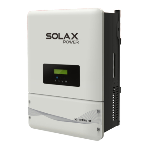
SolaX Power X3-Retro Fit Series User manual

SolaX Power

SolaX Power X3-Retro Fit Series User manual

SolaX Power X1 Series User manual

SolaX Power

SolaX Power X1 Series User manual

SolaX Power X1 Series User manual

SolaX Power

SolaX Power X1 Series User manual

SolaX Power X3-Fit-G4 User manual

SolaX Power

SolaX Power X3-Fit-G4 User manual

SolaX Power X1-MINI-G4 Series User manual

SolaX Power

SolaX Power X1-MINI-G4 Series User manual

SolaX Power X3-Hybrid-5.0-D User manual

SolaX Power

SolaX Power X3-Hybrid-5.0-D User manual

SolaX Power X1 Series User manual

SolaX Power

SolaX Power X1 Series User manual

SolaX Power BMS-PARALLEL BOX-II User manual

SolaX Power

SolaX Power BMS-PARALLEL BOX-II User manual

SolaX Power X1-ESS G4 User manual

SolaX Power

SolaX Power X1-ESS G4 User manual

SolaX Power X3-MIC-G2 User manual

SolaX Power

SolaX Power X3-MIC-G2 User manual

SolaX Power ZDNY-TL Series User manual

SolaX Power

SolaX Power ZDNY-TL Series User manual

SolaX Power X1-2.5-S-D User manual

SolaX Power

SolaX Power X1-2.5-S-D User manual

Popular Inverter manuals by other brands

Mastervolt WHISPER 3.5M3000 RPM user manual

Mastervolt

Mastervolt WHISPER 3.5M3000 RPM user manual

Omron KP**G-OD Series Communications manual

Omron

Omron KP**G-OD Series Communications manual

Cobra CPI1590 operating instructions

Cobra

Cobra CPI1590 operating instructions

Toshiba TOSVERT VF-nC1 instruction manual

Toshiba

Toshiba TOSVERT VF-nC1 instruction manual

Tektronix CFG250 Operator's manual

Tektronix

Tektronix CFG250 Operator's manual

Anritsu MG3710A Operation manual

Anritsu

Anritsu MG3710A Operation manual

C.E. Nierhoff & Co C524 troubleshooting guide

C.E. Nierhoff & Co

C.E. Nierhoff & Co C524 troubleshooting guide

Tascam CG-1800 owner's manual

Tascam

Tascam CG-1800 owner's manual

SMA SUNNY HIGHPOWER PEAK3 Quick reference guide

SMA

SMA SUNNY HIGHPOWER PEAK3 Quick reference guide

ALDI FERREX XG-KF2000 user manual

ALDI

ALDI FERREX XG-KF2000 user manual

Kohler KD2000 operating instructions

Kohler

Kohler KD2000 operating instructions

Sungrow SG30 33 40 50CX user manual

Sungrow

Sungrow SG30 33 40 50CX user manual

Toshiba Q7 Flow Installation and operation manual

Toshiba

Toshiba Q7 Flow Installation and operation manual

Fuji Electric Frenic-Mini user manual

Fuji Electric

Fuji Electric Frenic-Mini user manual

Dometic Go Power! GP-1750HD user manual

Dometic

Dometic Go Power! GP-1750HD user manual

VOLTWORKS VK-1100HB user manual

VOLTWORKS

VOLTWORKS VK-1100HB user manual

Voltronic Power 3KVA user manual

Voltronic Power

Voltronic Power 3KVA user manual

SMA WINDY BOY 3600TL user manual

SMA

SMA WINDY BOY 3600TL user manual

manuals.online logo
manuals.online logoBrands
  • About & Mission
  • Contact us
  • Privacy Policy
  • Terms and Conditions

Copyright 2025 Manuals.Online. All Rights Reserved.