CJ-8S20
JAPAN
6
General Safety Information
• It is important to completely understand
the operation of your bicycle's brake
system. Improper use of your bicycle's
brake system may result in a loss of
control or an accident, which could lead
to sever injury. Because each bicycle may
handle differently, be sure to learn the
proper braking technique (including
bicycle control characteristics) and
operation of your bicycle. This can be
done by consulting your professional
bicycle dealer and the bicycle owner's
manual, and by practicing your riding
and braking technique.
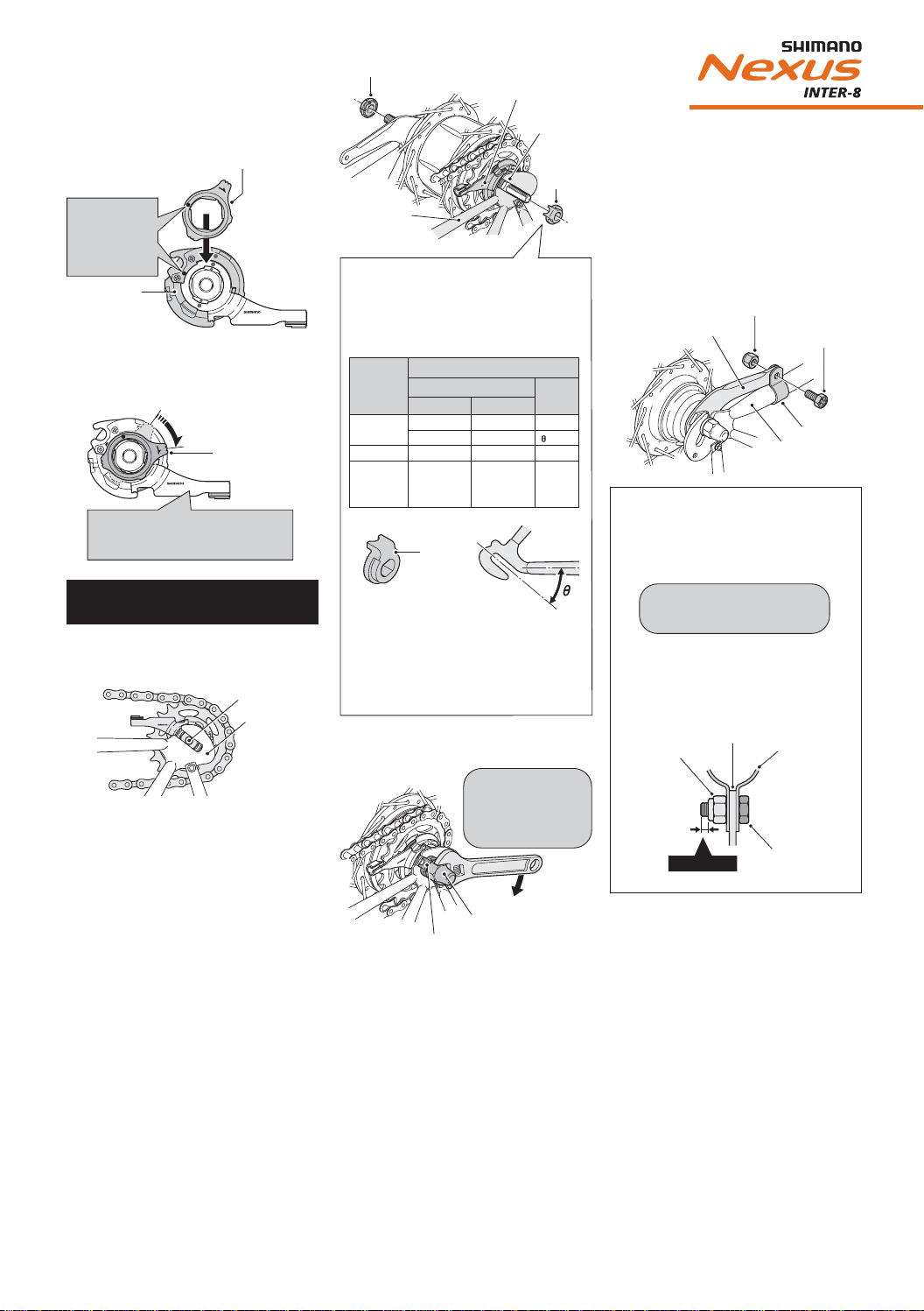
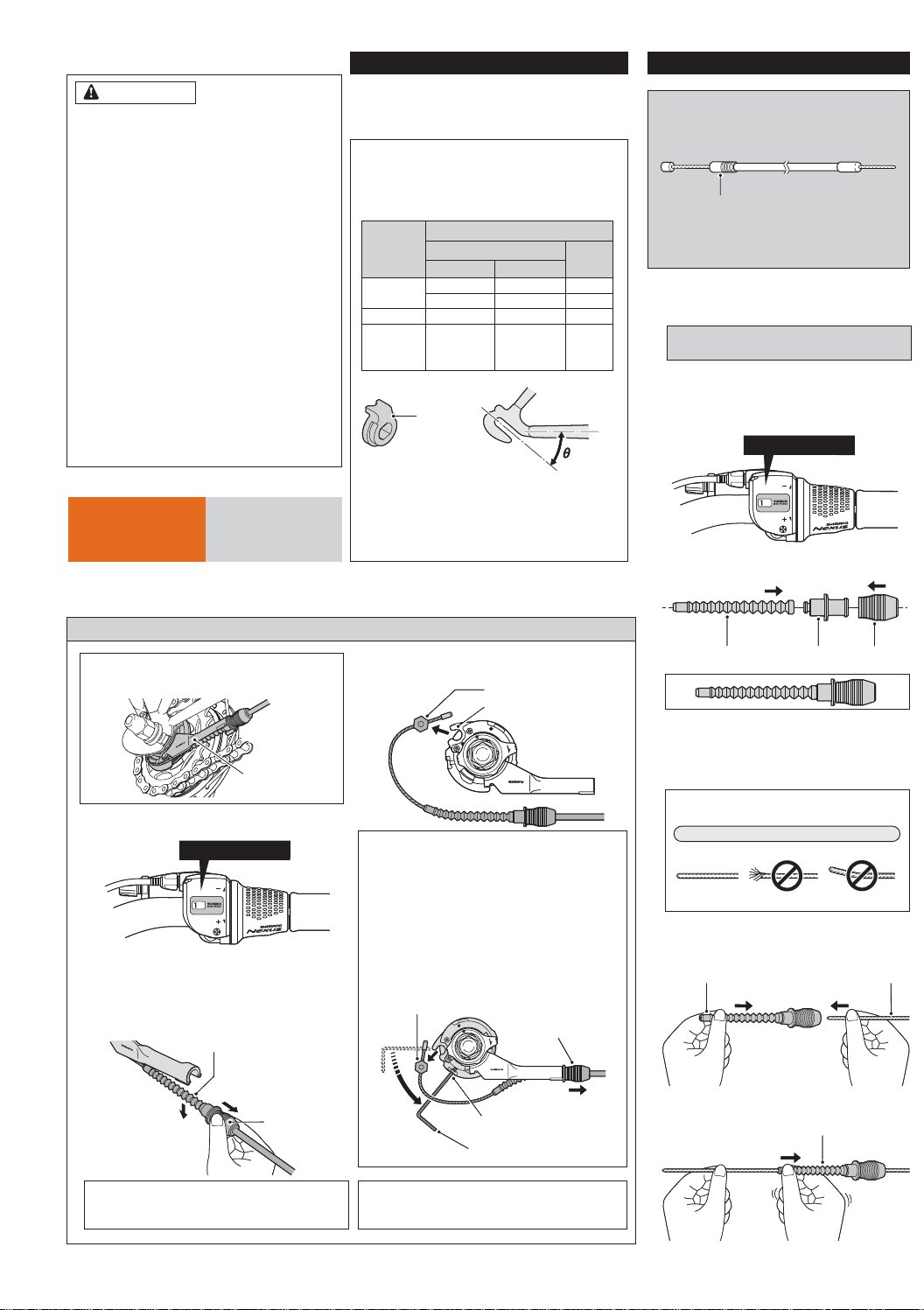
• When securing the brake arm to the
frame, be sure to use a brake arm clip
that matches the size of the chainstay,
and securely tighten them with the clip
screw and clip nut to the specified
tightening torque.
Use a lock nut with a nylon insert (self-
locking nut) for the clip nut. It is re-
commended that standard Shimano parts
be used for the clip screw, clip nut and
brake arm clip. In addition, use a brake
arm clip that matches the size of the
chainstay.
If the clip nut comes off the brake arm,
or if the clip screw or brake arm clip
becomes damaged, the brake arm may
rotate on the chainstay and cause the
handlebars to jerk suddenly, or the
bicycle wheel may lock and the bicycle
may fall over, causing serious injury.
• When installing the hub to the frame,
be sure to install the correct non-turn
washers to the left and right sides, and
securely tighten the hub nuts to the
specified torques. If the non-turn washers
are installed to one side only, or if the
hub nuts are not tightened sufficiently,
the non-turn washer may fall out, which
could cause the hub axle to rotate and
the cassette joint to turn. This may then
cause the handlebars to be accidentally
pulled by the shifting cable, and an
extremely serious accident could result.
• Obtain and read the service instructions
carefully prior to installing the parts.
Loose, worn, or damaged parts may
cause serious injury to the rider.
We strongly recommend only using
genuine Shimano replacement parts.
• Check that the wheels are fastened
securely before riding the bicycle. If the
wheels are loose in any way, they may
come off the bicycle and serious injury
may result.
• Read these Technical Service Instructions
carefully, and keep them in a safe place
for later reference.
• Avoid continuous application of the
brakes when riding down long slopes, as
this will cause the internal brake parts to
become very hot, and this may weaken
braking performance. It may also cause a
reduction in the amount of brake grease
inside the brake, and this can lead to
problems such as abnormally sudden
braking.
• Spin the wheel and confirm that the
braking force of the coaster brake is
correct.
• If the brakes are used frequently, the
brake drum may become hot. Do not
touch the brake drum for at least
30 minutes after you finish riding the
bicycle.
NOTE:
• You can shift gears while pedaling, but
on rare occasions the pawls and ratchet
inside the hub may produce some noise
afterwards as part of normal gear shift-
ing operation.
• The CJ-8S20 cassette joint should only be
used with sprockets from 16T to 23T.
• If the wheel becomes stiff and difficult to
turn, you should replace the brake shoes
or lubricate with grease.
• Do not apply any lubricant to the inside
of the hub, otherwise the grease will
come out.
• You should periodically wash the sprock-
ets in a neutral detergent and then
lubricate them again. In addition, clean-
ing the chain with neutral detergent and
lubricating it can be a effective way of
extending the useful life of the sprockets
and the chain.
• If the chain keeps coming off the sprock-
ets during use, replace the sprockets and
the chain.
• Parts are not guaranteed against natural
wear or deterioration resulting from
normal use.
• For maximum performance we highly
recommend Shimano lubricants and
maintenance products.
• For any questions regarding methods of
handling or adjustment, please contact
the place of purchase.
WARNING – To avoid serious
injuries: CAUTION – To avoid serious
injuries:
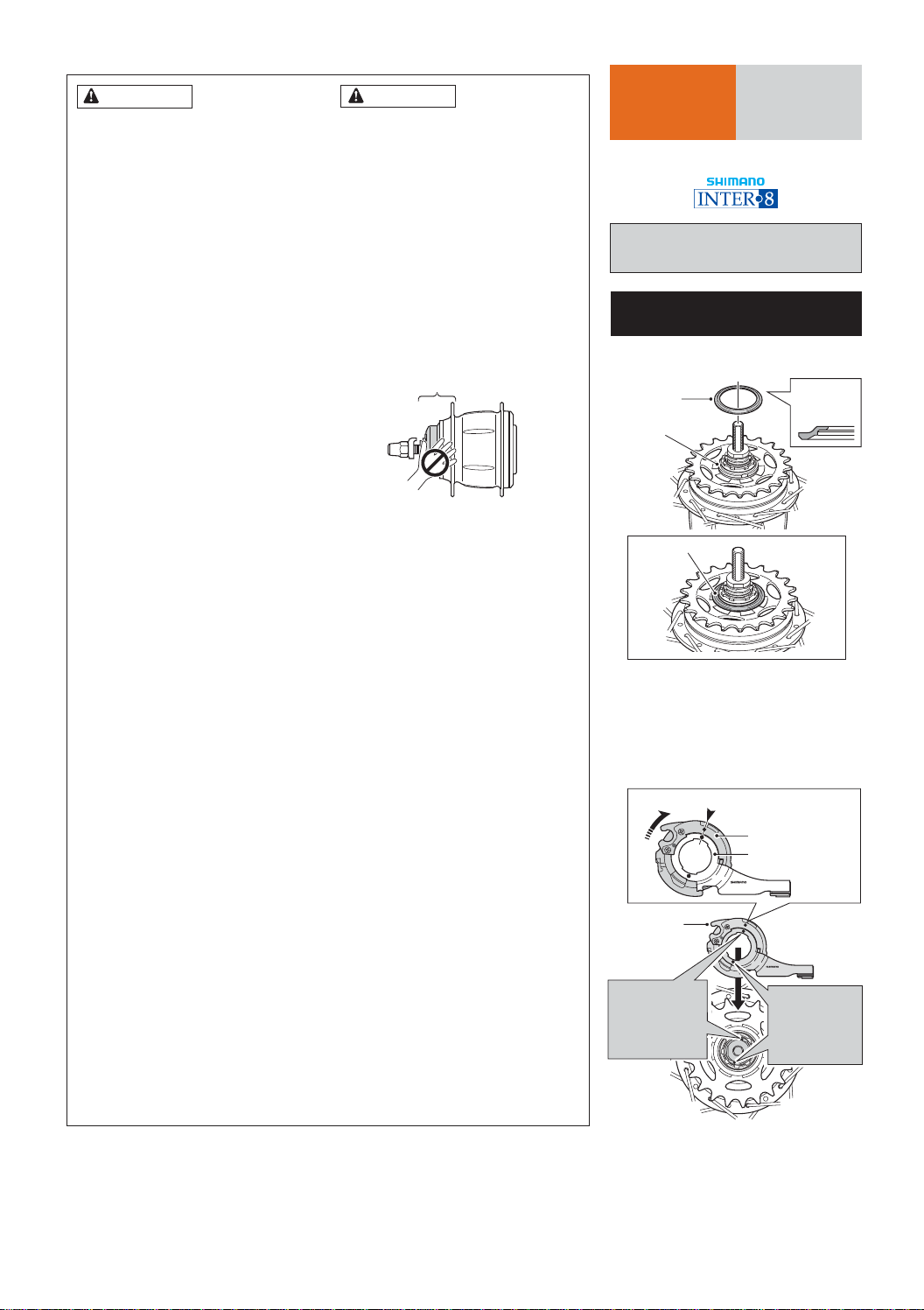
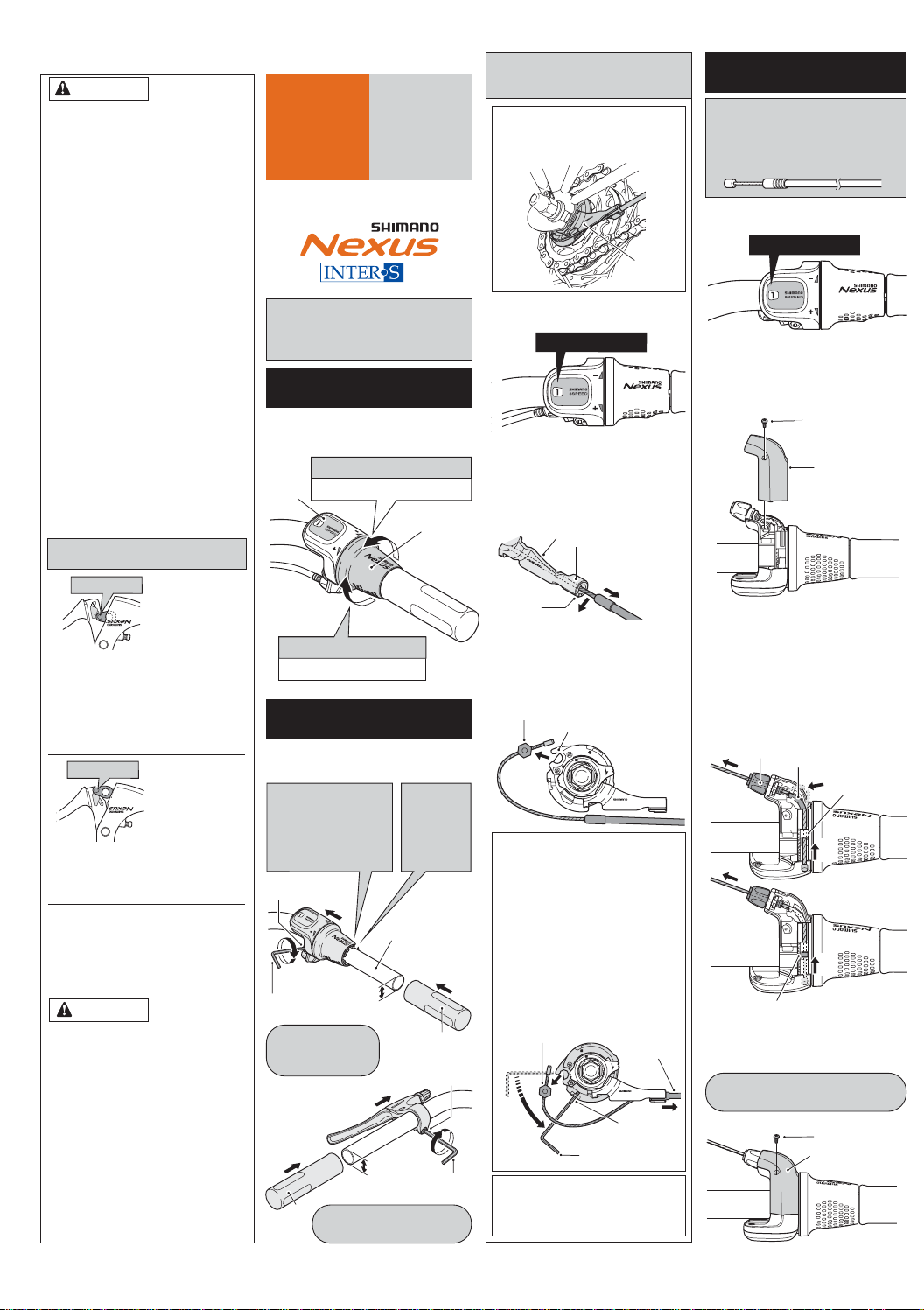
Brake drum Driver cap
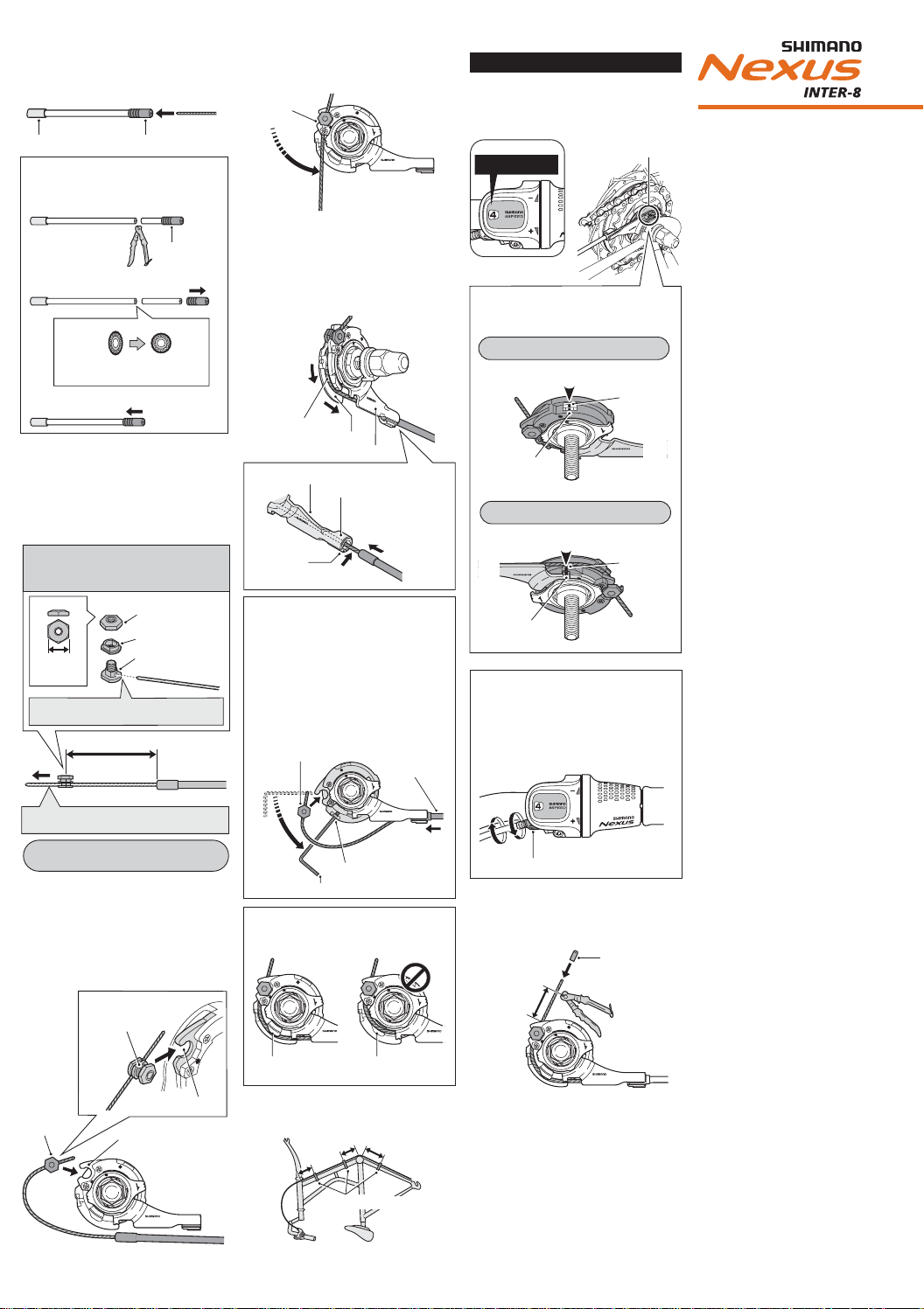
Installation of the cassette joint
to the hub
1. Install the driver cap to the driver on the
right side of the hub body.
2. Turn the cassette joint pulley in the
direction of the arrow in the illustration
to align the red ● marks on the pulley
and the bracket. With the cassette joint
in this condition, install it so that the
red ● mark on the cassette joint is
aligned with the red ● mark on the
right side of the hub body.
Driver
Driver cap
Pulley
Bracket
Note the
direction
Should be aligned
Cassette joint
Align the
red ● marks
to install.
Align the
red ● marks
to install.
Right side of
the hub body
Technical Service Instructions
Be sure to read these service instructions in
conjunction with the service instructions for
the INTER-8 shifting lever before use.
INTER-8 Hub
with Coaster Brake
SG-8C20
CJ-8S20
SI-35P0A
Cassette Joint
Lay_INTER-8_GB 05 23.12.qxd 23.12.2004 13:39 Uhr Seite 6