Shin-Nippon BR-7 User manual

r
μπα
να
2
LT
|
SHIN-NIPPON
REFRACTOR
MODEL:
BR—
7
SERVICE
MANUAL

CONTENTS
1.
Introduction
1-1
Features
of
the
Product
1-2
Qualified
Service
Person
1-3
How
to
Use
the
Service
Manual
1-4
Layout
Plan
of
Optical
Parts
1-5
Name
and
Performance
of
Parts
2.
Service
Items
Disassembly/Inspection/Adjustment
Procedure
3.
Remarks
371
Adhesion,
Kind
of
Oil
and
Application
Point
3-2
Service
Tools
+14
18

q.
RS
a
σον
+
eee
meme
e
qe,
기
Introduction
Features
of
the
Product
We
offer
with
confidence
this
optometer
as
a
self-
canscious
optometer
completed
while
incorporating
necessary
and
sufficient
functions
on
the
basis
of
invaluable
experiment
of
those
who
actually
engage
in
optometry
and our
long
experience
in
this
field.
This
product
will
meet
the
demand
of
those
who
want
correct
and
rapid
optometry.
The
beautiful
appearance
and
comprehensive
functions
of
the
product
will
surely
prove
satisfactory:
(1)
The
cross
cylinder
and
rotary
prism,
which
are
of
a
double
loupe
(turret)
type,
help
keeping
a
constant
distance
from
the
eyes,
ensuring
precision
measurement
and
easy
use.
(2)
A
synchronous
mechanism
allows
the
cross
cylinder
loupe
to
move
automatically
while
being
interlocked
with
a
cylindrical
axis,
ensuring
highly
effective
precision
measurement
of
the
astigmatism.
(3)
Easy
operation
through
front
observation
and
front
operation
(4)
Large
power
indicator
window,
enabling
easy
reading
(S)
Wide-ranging
inspections
(binocular
visual
function

sette
e
TO
1-2
1-3
inspection,
etc.)
possible
through
combination
of
a
visual
acuity
tester
and
abundant
auxiliary
lenses
(6)
In
a
convergence
mechanism
for
near
distance
inspection,
the
entire
optical
mechanism
can
be
correctly
set
through
lever
operation.
(7)
Eaceïshieïlds
and
an
optometry
window
are
provided
With
a
coated
dust-proof
glass
which
prevents
light
reflection
and
contamination
of
the
lenses
in
the
equipment.
Qualified
Service
Person
Servicing
of
this
product
must
be
made
by
a
person
who
is
experienced
in
assembly
and
adjustment
of
the
medical
equipment
(in
particular,
the
reflector
head).
It
is
recommended
for
the
others
to
attend
the
course
on
servicing
technology
of
Towa
Co.,
Ltd.
How
to
Use
the
Service
Manual
(1)
The
service
operation
must
be
based
on
the
flow
chart
shown
below.
(
Trouble
Understanding
the
cause
of
trouble
|

pe
TTT
σος
ο
πο
一
一
一
Servicing
NO
一
necessary?
(2)
(3)
(4)
>
Servicing
Inspection
Cleaning
<
y
Packing
End
Carry
out
disassembly,
servicing,
assembly
and
adjustment
of
the
optical
system
in
a
clean
place
where
there
is
no
adverse
effect
on
the
product
due
to
dust,
etc.
Always
observe
the
manual
thoroughly
and
use
the
specified
materials
and
tools,
ensuring
correct
and
reliable
servicing.
Basically,
replace
the
metal
parts
as
individual
pieces
and
the
optical
system
components
as
a
unit.
~5-

a
art
verita
dl
=
(5)
For
disassembly
and
assembly
of
parts
not
described
in
this
manual,
refer
to
the
service
parts
list.
(6)
Never
use
the
lubricating
oil
other
than
the
one
specified.
(7)
Order
the
service
parts
while
referring
to
the
service
parts
list.
1-4
Layout
Plan
of
Optical
Parts
Sl
(spherical
disk)
Madox,
red
Deflection
45°
ACC
(accessory)

EL
pie
n
RE
NT
TR
τος.
R
L
Ro»
7
CNV
AORN
/
]
|
HY
ROD
Ap
Ci
astigmatic
disk
C2
astigmatic
disk
ses
Cross
cylinder
and
rotary
prism
1-5
Name
and
Performance
of
Parts
M.
VĚ
1
28

ee
iai
gg
de
No.
Name
No.
_
Name
©
Level
adjusting
knob
02
Cross
cylinder
(2)
'
PD
scale
©
Loupe
3
Forehead
rest
adjusting
knob
©
Cornea
focus
A)
Level
shaft
09
Astigmatic
scale
plate
⑤
Level
⑯
Cylindrical
axis
scale
plate
©
Head
cover
00
Astigmatic
case
D
PD
adjusting
knob
08
Power
handle
©
Convergence
knob
©
Cylindrical
axis
knob
©
Auxiliary
lens
scale
plate
00
Astigmatic
lens
knob
00
Auxiliary
lens
knob
21
Forehead
rest
⑪
Rotary
prism
|
22
Cheek
rest
23
Spherical
case
Service
Items
D
Adjustment
of
the
lateral
movement
and
play
of
PD
Adjustment
of
the
deviation
and
play
of
the
astigmatic
lens
holder
Adjustment
of
the
turret
Adjustment
of
the
stopper
roller
of
each
disk
plate
Adjustment
of
the
cornea
scale
Replacement
of
the
cross
cylinder

σα
σας
or,
ποτ
καν
νο
ο."
πω,
”~
一
一
”下
Disassembly/Inspection/Adjustment
Procedure
Illustration
Procedure
6)
ta?
[es]
t £
th
lateral
daiane
jrs
Loosen
to
remove
Fa
spring
case
(#6)
and
remove
spring
guide
(#9)
and
level
coll
(#4).
loosen
lwo
screws
6R
3x8
(#2)
and
remove
lhe
head
cover
(41).
Loosen
Lo
remove
6W
3x8
(#19)
and
remove
the
PD
knob
(#12),
Loosen
to
remove
two
screws
68
3x8
(411)
and
remove
the
PD
bearing
#10),
Turn
two
to
three
times
to
loosen
four
screws
6S
3x8
(#7)
on
the
Guide
plate
(#8)
and
adjusl
the
laleral
movement
and
play
of
pp
with
four
screws
GU
3x5
(#6)
of
the
nead
(#9),
(See
Fig.
1)
(2)
Adjusting
the
deviation
and
play
of
the
astigmatic
lens
holder
Tighten
or
lvwsen
the
holder
fixing
screw
(815)
and
serew
6U
2.6x3
(#16)
on
the
lens
holder
(#14)
and
adjusl
the
deviation
and
play
of
the
lens
holder.
(See
Fig.
2)

тот
о
р
unii
в
ere
이
게제
ae
ο
前
a
er
Illustration
Procedure
#18
(8)
Adjusling
the
lurret
(1)
Lateral
adjustment
1.
Adjust
the
lateral
movement
of
the
lurrel
wilh
a
Screw
U
4x4
(H18)
op
the
side
of
lhe
click.
mount
(#17),
(See
Fig.
3)
(2)
Vertical
adjustment
l.
Loosen
three
screws
CRs
2x3
(#819)
and
remove
lhe
cover
(820),
Dm
lLoosen
a
serew
6U
2x3
($21)
and
remove
a
cenler
gear
(422).
3.
Carry
oul
verlical
adjustment
of
the
lLurret
wilt
a
ring
nul
(#24)
and
hexagon
nul
(#23).
,
(See
Fig.
4)
-10-
SE
AT
TO
ET
EE
ME
a
이
Illustration
,
Procedure
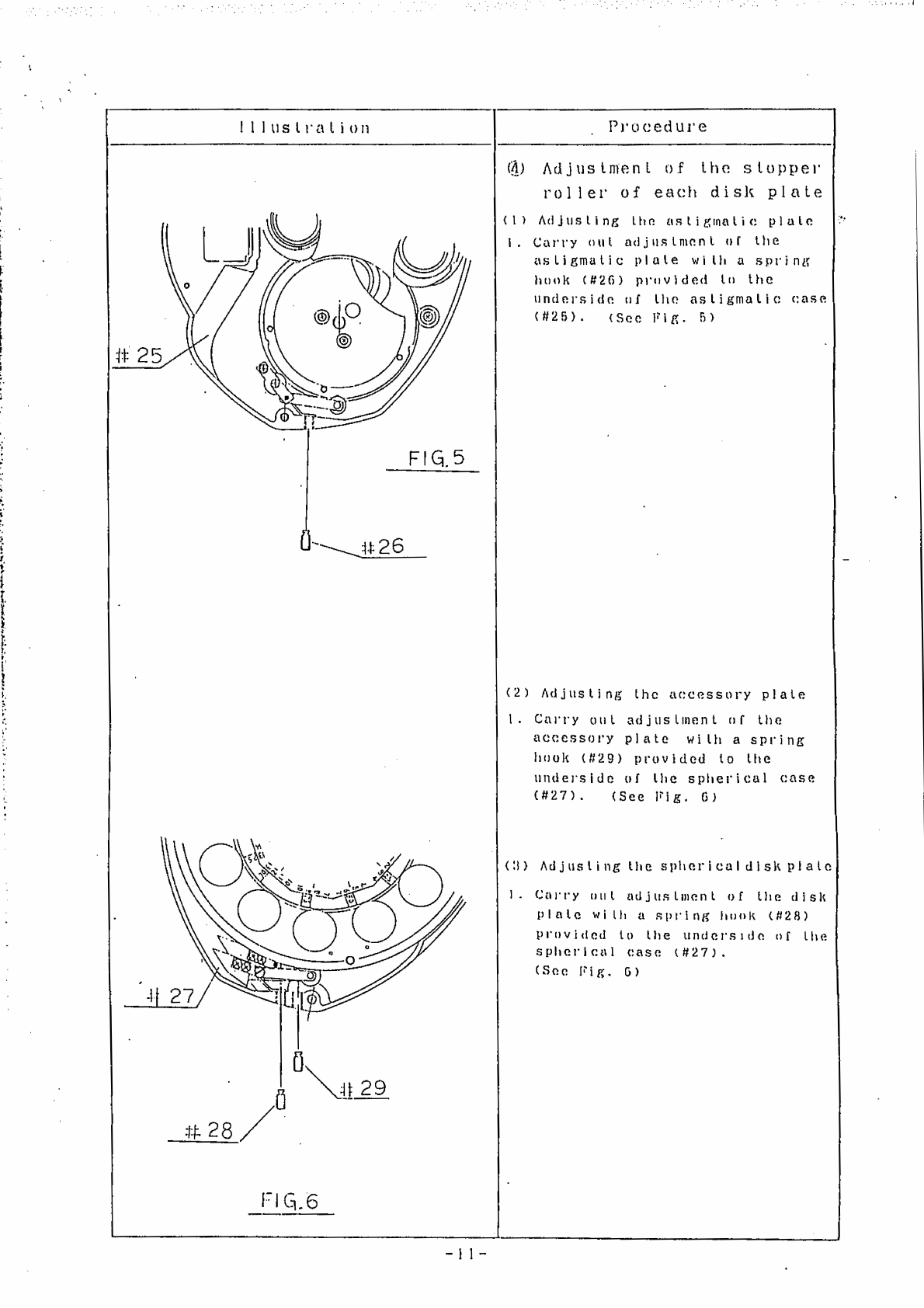
à)
Adjustment
of
the
stopper
roller
of
each
disk
plate
(1)
Adjusling
the
asligmatic
plale
I.
Carry
oul
adjustment
of
the
asligmatic
plale
with
a
spring
hook
(#26)
provided
to
the
underside
of
the
astigmalic
case
(#25).
(See
Fig.
5)
FIGS
—
4426
(2)
Adjusting
the
aceessory
plate
し.
Carry
out
adjustment
of
the
accessory
plate
wilh
a
spring
hook
(#29)
provided
to
the
underside
of
the
spherical
case
(#27).
(See
Fig,
6)
(3)
Adjusting
the
sphericaldisk
plate
1.
Carry
oul
adjuslment
of
the
disk
pPlale
wilh
a
spring
hook
(828)
provided
to
the
underside
of
Lhe
spherical
case
(#27).
(See
lig.
6)
=]]-
Ань
+.
ль
1
dii
İNE
RR
lele
ln
A
PR
Iliustralion
Procedure
#
31
FIG.8
bhe
©
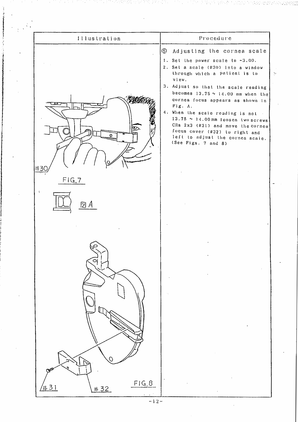
Adjusting
the
cornea
scale
Sel
lhe
power
scale
lo
-3,00,
Sel
a
scale
(#30)
inlo
a
window
through
which
a
Patienl
is
to
view,
Adjust
sa
that
the
scale
reading
becomes
13.75»
14,00
mm
when
the
cornea
focus
appears
as
shown
in
Fig.
A,
When
the
scale
reading
is
nol
13.75
%
14,00
mm
Ivosen
two
screws
CRs
2x3
(#31)
and
move
lhe
cornea
focus
cover
(#32)
lu
right
and
left
to
adjust
the
cornea
scale.
(See
Figs.
7
and
8)
|
ー1
2ー

In
es
tampar
rt
pao
da
ARS
porre
ae
Illustralion
Procedure
#
36
FIG.9
(6)
Replacing
the
cross
cylinder
1.
Loosen
four
serews
Chts
2x3
($23),
and
remove
an
indicalor
plale
|
(#34)
and
spring
(#35),
Then,
replace
the
cross
cylinder
(#36).
(See
Fig.
9)
Note:Replacement:
‘of
:C+—0.:37¢and.-
С+-0.
50
sis:possible
optionally:
=
13-
|
FN
nm
on
ュー
e
a
Ce
SORT
RR
a
ee
A
i
r
sj
“ro
es
:
ft
oy
Di
tae
2444
ту
Va
Note:
feripacemen
i
af
116,37
end
C1i0,56
te
pussibte
ο.
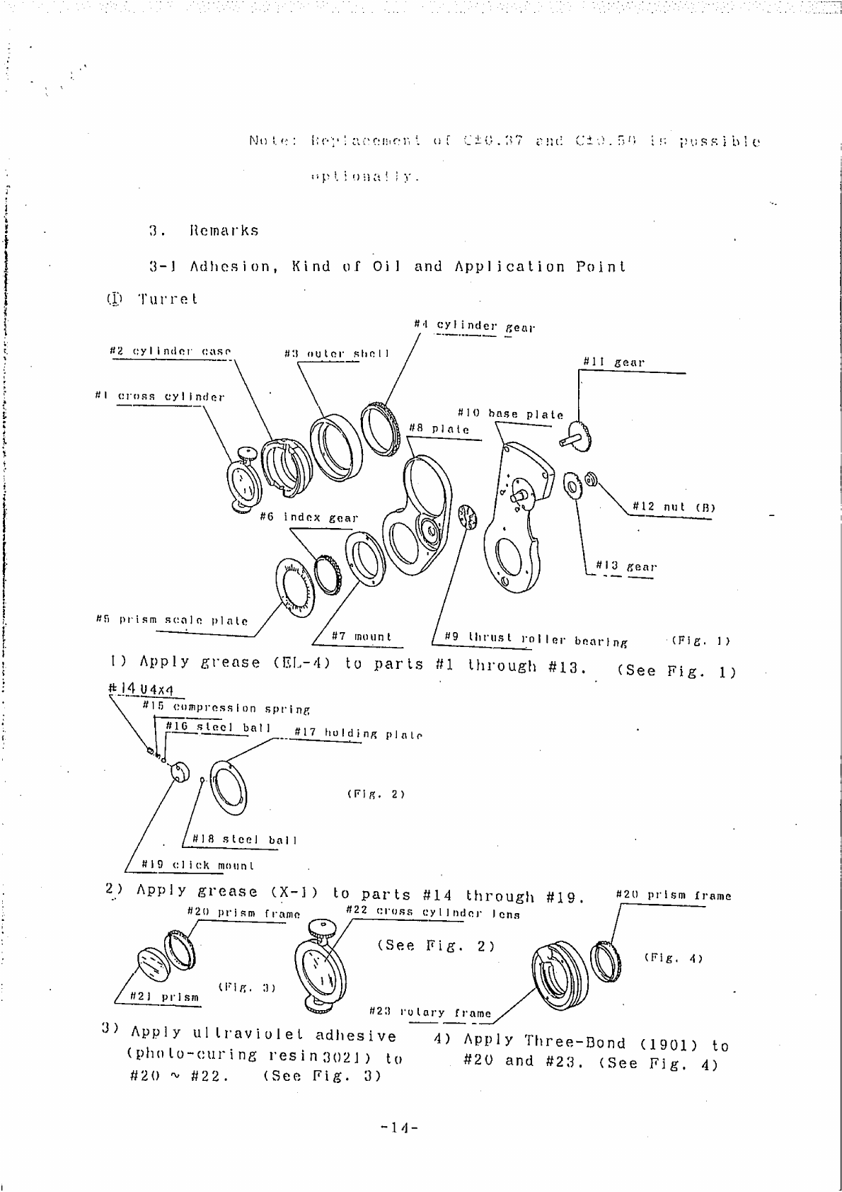
3.
Remarks
3-1
Adhesion,
Kind
of
Oi]
and
Application
Point
(D
Turret
Rd
cylinder
gear
#2
cylinder
case
#
outer
shell
gear
Bl
cross
cylinder
——
#10
base
plate
#8
plate
©,
Ne:
nut
(B)
—
—
mi
#6
index
gear
SIG
#13
gear
©
47
mount
#9
thrust
ist
roller
bearing
(Fig.
1)
1)
Apply
grease
(EL-4)
to
parts
#1
through
#13,
(See
Fig.
1)
#
14
0484
ТЕ
RR
prism
scale
plate
compression
spring
#16
stecl
bal]
#17
hulding
plate
mm,
©
(Fig.
2)
#18
steel
bail]
#19
click
mount
2)
Apply
grease
(X-1)
to
parts
#14
through
#
#20
prism
frame
:
420
prism
frame
#22
cross
cylinder
Jeng
SN
(See
Fig.
2)
(Fig.
4)
(Fig.
1)
#2)
prism
“一
一
一
一
#29
vulary
fr
frame
9)
Apply
ullravivolet
adhesive
4)
Apply
Three-Bond
(1901)
to
(pholo-curing
resin3021)
to
#20
and
#23.
(See
Fig,
4)
#20
~
#22. (See
Fig.
3)
-l4-

PAR
Mrs
OR
EAU
Fr
©
“lead
support
#24
forehead
|
#25
shaft
case
#26
thrust
roller
bearing
#27
forehead
resi
sorew
(Fig.
5)
#28
knob
1)
Apply
grease
(001)
to
Parts
#24
through
#28.
(See
Fig.
5)
#31
Knob
#39
level
bearing
#34
washer
#32
washer
#35
level
screw
#39
slide
3)
Apply
grease
(001)
to
parts
#31
through
#36.
(See
Fig.
7)
#41
PD
serew
and
nut
5)
Apply
grease
(005)
to
parts
#41
and
#42.
(See
Fig.
9)
(Fig.
7)
L
#36
level
Shaft
bearing
rest
shaft
#29
holder
Pin
(Fig.
6)
#30
scale
holder
2)
Apply
grease
(X-1)
to
parts
#29
and
#30.
(See
Fig.
6)
#37
leve]
coi]
#40
shaft
4)
Apply
grease
(X-1)
to
parts
#37
through
#40.
(See
Fig.
8)
#42
PD
bearing
#44
65
2x6
#43
Plate
(Fig.
10)
6)
Apply
silicon
(liquid
type
RTV
rubber
of
Shin-Etsu
Silicon)
to
parts
#43
and
#44,
(See
Fig.
10)

A
TT
©
Spherical
case
HAS
lens
$46
prism
#49
Madox
(Fig.
11)
(Fig.
12)
#48
filter
O
|
1)
Apply
ultraviolet
adhesive
(photo-curing
.#50
polaroid
disk
resin
3021)
to
parts
#45
»
#47.
|
2)
Apply
GS
cement
to
parts
(See
Fig.
11)
| |
#48
to
#50.
(See
Fig.
12)
#51
feed
Plate
shaft
4
#56
wheel
pipe
.
SÌ
m_
#51
seat
metal
.
#58
steel
ball
#57
thrust
#52
thrust
+
+
roller
bearing
Es
Me”
roller
bearing
(Fig.
14)
全
、
στο
#53
thrust
roller
bearing
|
$
RD
sa
nut
4)
Apply
grease
(X-1)
to
the
part
#58.
(See
Fig.
14)
(Fig.
13)
#55
gear
3)
Apply
grease
(EL-4)
to
parts
$51
through
#57.
(See
Fig.
13)
©
Near
point
scale
#59
spring
#60
sleel
ball
1)
Apply
grease
(X-1)
to
parts
#59
to
#61.
(See
Fig.
15)
#61
card
holder
(Fig.
15)
®
Near
point
scale
holder
(Fig.
16)
1)
Fill
a
port
A
with
machine
oil.
(See
Fig.
16)
#63
scale
holder
#62
level
angle
~
«16
--

Wee
о
mi
em a
+
Fair
sr
etě
ra
‘)
Asligmatic
case
#64
thrust
ruller
bearing
%
#65
cylinder
flange
(Fig.
17)
#67
shaft
1)
Apply
grease
(EL-4)
to
parts
#64
through
#67.
(See
Fig.
17)
#72
cylindrical
axis
gear
#71
bearing
(Fig.
19)
3)
Apply
grease
(X-1)
to
parts
#71
and
#72.
(See
Fig.
19)
D
Accessories
“ο
(Fig.
21)
#74
dust-proof
glass
~
j=
e
1)
Apply
Three-Bond
(1782)
to
the
part
#74.
(See
Fig.
21)
#06
holder
#70
astigmatic
case
#63
cylinder
cover
#69
washer
2)
Apply
ultraviolet
adhesive
(photo
-curing
resin
3021)
to
the
part
#68
and
apply
Three-Bond
(1782)
to
parts
#69
and
#70.
(See
Fig.
18)
(Fig.
20)
4)
Apply
GS
cement
ta
all
of
lenses
(#73)
in
the
lens
holder.
(See
Fig.
20)
‘#75
lens
holder
=
(Fig.
22)
4
a»
—
#76
lens
2)
Apply
ultrasonic
adhesive
(photo
“curing
resin
3021)
to
Parts
#75
and
#76.
(See Fig.
22)
—17
—

Service
Tools
1.
Set
screwdriver
(standard
and
Philips
screwdrivers
#0).
à,
2,
Hexagonal
wrenches
(1.5,
2.0,
2.5
and
3.0
mm)
3.
Radio
pliers
No
other
dedicated
tools
than
those
specified
above
will.
not
be
necessary
for
the
service
work
desoribed
in
this
manual.
-18-
Other manuals for BR-7
1
Table of contents
Other Shin-Nippon Medical Equipment manuals


Popular Medical Equipment manuals by other brands

sensiplast
sensiplast 298610 Instructions for use

Moog
Moog CURLIN 340 manual

Dräger
Dräger Infinity Acute Care System Workstation Critical... Supplement to instructions for use

CSZ
CSZ Blanketrol_ii Operation and technical manual

Breas
Breas NIPPY Clearway Clinical Guide

ADC
ADC 5110N Series Instructions for use


