Shin-Nippon ACCUREF-K 9001 User manual

RB-400-B02D
AUTOREFKERATOMETER
ACCUREF-K
9001
Operations Manual

RB-400-B02D1
INTRODUCTION
This manual contains information on correct handling and operational procedures as well as safety
consideration pertinent to ACCUREF-K 9001.
Before carrying out measurement and/or adjustment, read the instructions thoroughly so that effective
operation is ensured. As this constitutes an important reference and user guide, keep it on hand at all times.
NOTE
The information contained in this manual is subject to change without notice.
While reasonable efforts have been made in the preparation of this document to ensure its accuracy,
you should contact your local distributor immediately, if any quarries arise due to editorial errors or
omissions etc.
SAFETY CONSIDERATION
ACCUREF-K 9001 is a Class I, Type B medical instrument as well as LED Class 2 product.
This instrument complies with Medical Device Directive 93/42/EEC.
A great deal of consideration has gone into the design and manufacturing of this instrument with regard to
its operational ease, the patient's safety and well-being as well as to the reliability of the product.
For safer and more effective use, however, follow the points described in this manual.
This instrument is designed for professional use.
~ General Definitions of Safety Symbols ~
CAUTION General warning. Caution.
Risk of danger.
Caution of invisible LED
radiation.
Avoid exposure to beam.
Indicated inside of the device.
No specific definition given.
Denotes general ban or
prohibition. LED Class 2 Product This device is a LED class 2
product.
General mandatory action.

RB-400-B02D2
CAUTION
Always take great care when operating ACCUREF-K. Malfunction or damage to the instrument could
occur.
Cut the power immediately if malfunction occurs during operation. Damage to the equipment or
personal injury will result. Consult your dealer, if repair work needs to be carried out.
At no time attempt to remodel or disassemble ACCUREF-K. Damage to the instrument or personal
injury will result.
As ACCUREF-K is a precision optical instrument, operations must be carried out at all times by
experienced, authorized personnel. Damage to the equipment or personal injury will result.
Avoid installation near TV or radio. The reception can be disturbed by electrical noise. Follow the
manual for the proper installation.
Never remove the plug from the outlet if your hands are wet. Electric shock or personal injury could
result.
Make sure the power cord is not damaged. Fire or electric shock may occur.
Do not touch the optical parts. Measurement accuracy will be adversely affected.
The power cord must be firmly connected to an electrical ground (safety ground) at the power outlet.
Personal injury may result form electric shock, etc.
If the instrument fails to work properly, you should not try to repair the fault. Consult your dealer
immediately.
The instruction in this manual ensures correct operations.
Observe the following environmental conditions for used and storage. Avoid dew condensation at all
time. Temperature Relative humidity
Use +10°C to +40°C 30% to 85%
Storage –10°C to +60°C below 70%
Avoid the following conditions for storage and use of the instrument.
Where noxious gases or air pollutants are present.
Where dust and grit may occur.
Where oil fumes or greasy substances are emitted.
Where there are atmospheric concentrations of salt.
Near gas generation areas and places where dust accumulates.
Keep in a secure, stable situation. Do not expose to strong vibrations (areas of seismic activity) and
sudden shocks (this includes transportation) etc.
Where there is an inclination of more than 10 degrees.
Where voltage from the power sources rises or falls sharply during loading.
Where fluctuations in the voltage of the power source occurs.
Direct contact with sunlight.
If the instructions above are not followed, damage to the equipment or personal injury will ensue.

RB-400-B02D3
CONTENTS
Introduction.........................................................................................................................1
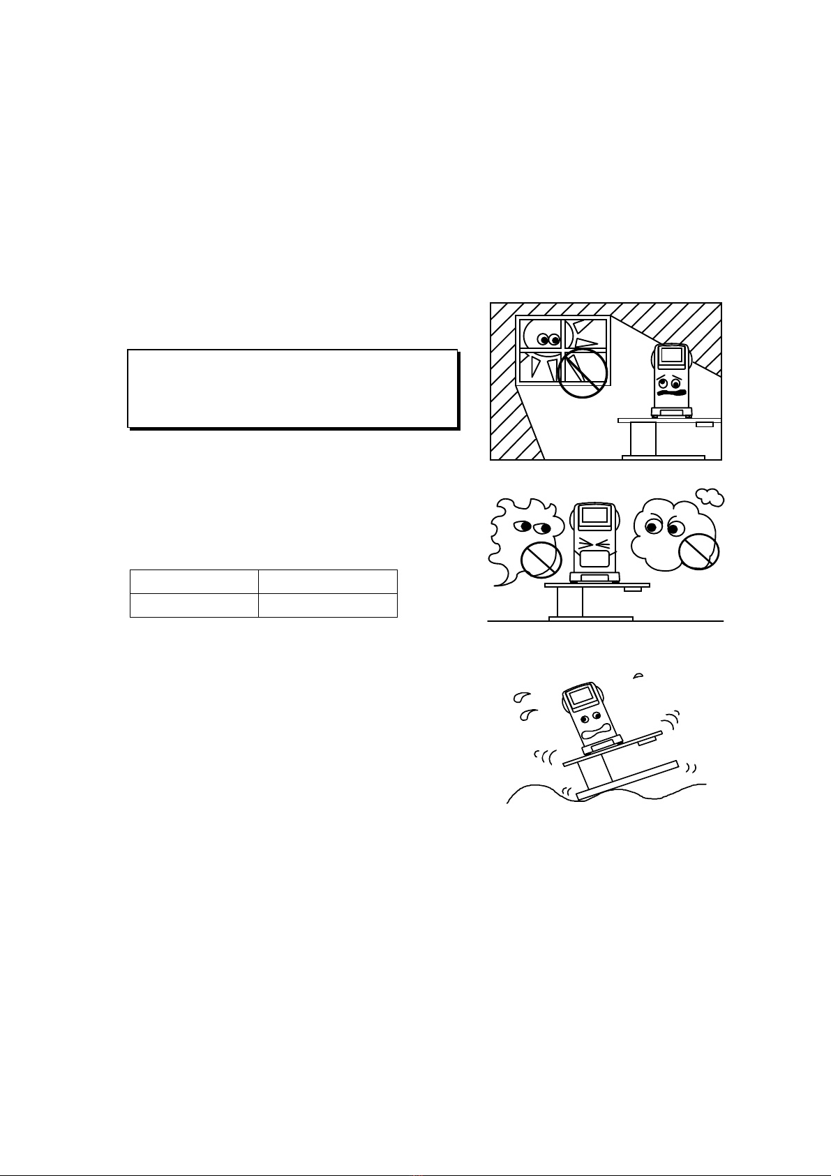
Safety Consideration..........................................................................................................1
Accessories.........................................................................................................................4
1. Parts Identification.......................................................................................................5
2. Conveyance and Handling Procedure........................................................................6
3. Installation Environment..............................................................................................6
4. Safeguard Summary ....................................................................................................7
5. Preparation...................................................................................................................8
5.1 Setting ........................................................................................................................................8
5.2 Applying Power ..........................................................................................................................9
5.3 Standby ....................................................................................................................................10
5.4 Switch Function........................................................................................................................11
6. Measurement..............................................................................................................12
6.1 Measurement Flow...................................................................................................................12
6.2 Alignment..................................................................................................................................13
6.2.1 R/K, K, and P・K mode......................................................................................................13
6.2.2 R mode .............................................................................................................................15
6.3 Measurement Results ..............................................................................................................15
6.4 Print Out ...................................................................................................................................16
6.5 Kerato-Peripheral Measurement..............................................................................................17
6.6 IOL Measurement Function......................................................................................................19
6.7 Menu Screen Setting................................................................................................................20
6.7.1 Each Item Description.......................................................................................................21
6.7.2 Optional Functions............................................................................................................24
6.8 Auto Start Function...................................................................................................................28
6.9 Data Screen Function...............................................................................................................29
6.10 Power Saving Function ............................................................................................................30
6.11 Output Terminal........................................................................................................................30
7. Tips for Effective Measurement ................................................................................ 31
8. Error Messages..........................................................................................................32
9. Contact Lens: Base Curve Measurement................................................................. 33
10. Storage and Maintenance..........................................................................................34
10.1 Reloading Printer Paper...........................................................................................................34
10.2 Fuse Replacement ...................................................................................................................35
10.3 Storage.....................................................................................................................................35
10.4 Confirmation of Measurement Accuracy..................................................................................36
11. Specification...............................................................................................................37

RB-400-B02D4
Accessories
Model Eye: 1
with a contact lens holder
A sticker indicating the
diopter value is affixed.
Power Cord: 1
(2.5m) Printer Paper: 3
(width 57mm)
Two packed and one installed
into the body
Fuse: 2
(T2A 250V) Pack of Chin Rest Liners: 1
(1,000 sheets) Chin Rest Liner Pin: 2
Dustproof Cover: 1 Operations Manual: 1
Use accessories specified by us to avoid any malfunction or failure.
Extra care should be taken for storage of a model eye. Avoid where the lens of the
model eye may be damaged as well as any dusty or humid/steamy environments.
Avoid direct sunlight, humidity and high temperature when storing printer paper
which is a thermal paper.

RB-400-B02D5
1. Parts Identification
Printer
Body
Base
Measurement Mode
Selection Switch
IOL Switch
Anti-sliding lock
ACCUREF
‐
K
AUTOREFKERATOMETER
90
Menu Switch
Print Switch
Power Indicator
LCD Monitor
Head Rest
Eye Mark
Chin Rest
External Interface Connector
Output Terminal for External Monitor
Power Plug Connector
Fuse Holder
Joystick
Measurement
Start Switch
SHIN‑NIPPON
Power Switch
View Window
Nameplate

RB-400-B02D6
2. Conveyance and Handling Procedure
When transporting the instrument, make sure that the body has been securely locked.
Center the body onto the base so that their edges are aligned. Push up the lock while turning right until
both body and base are firmly fixed to each other.
3. Installation Environment
1) Do not expose the instrument's view window directly
to the sunlight or bright lighting from other sources.
2) Do not operate in places where either dust or rubbish
accumulates. Environment with extremes in heat and
humidity should also be avoided.
Always follow the environmental requirements below
for installation.
Temperature
+10 °C ~ – 40°C
Relative Humidity
30 % ~ 85 %
3) Keep away from inflammable or explosive gases as
well as storage areas housing medical supplies and chemicals.
4) Avoid installing where dew condensation may accumulate.
Also, avoid where the radical temperature changes may
occur.
5) Keep away from sites that may experience strong vibrations
or sudden shocks.
6) Malfunction is likely to occur if the instrument is improperly stabilized or accidentally overturns.
To prevent internal/external damage caused by sudden impact, set the instrument on a solid and
secure surface. Do not store in high, 'out of reach' places.
Great care should be taken and avoid that the
examinee is exposed to strong light or glare. The
pupil will contract too much for measurement to
be carried out.
Dust Gases

RB-400-B02D7
4. Safeguard Summary
1. ACCUREF-K is a precision optical instrument. Always handle with care and avoid dropping it
accidentally.
2. Ensure that the instrument is properly grounded when connected to the power source.
3. Do not touch the optical parts with fingers and be sure to avoid dust, as their measuring accuracy
could be adversely affected and incorrect values may result.
4. If the surfaces of the measuring unit and main unit including the
control panel are dirty, gently wipe with a dry cloth. For hard to
remove stains, a damp cloth or neutral cleanser is
recommended.
5. Clean the chin rest and head rest with the neutral cleanser. For disinfecting them, especially where the
examinee may contact, hydrogen peroxide (Oxydol) is recommended.
6. If the instrument is not used for any length of time, remove the
power cord from the outlet.
7. When not in use, protect the instrument with a supplied
dustproof cover.
8. When the instrument fails to function properly, never
attempt to perform internal service or adjustment. Contact
your nearest registered agent, distributor or retail outlet.
When dust or fingerprints appear on the optical part, use a soft cloth to wipe off
the build-up. In case that the build-up is hard to remove, absolute alcohol is
recommended. Take great care when cleaning these parts as they are particularly
sensitive and fragile.
Avoid using organic solvents that will
damage the water based paint finish of the
instrument.
Thinner
Benzene

RB-400-B02D8
5. Preparation
5.1 Setting
(1) Set a roll of printer paper in the printer. Refer to '10.1 Reloading Printer Paper' for the procedure.
(2) Set and fix the chin rest liners with the chin rest
liner pins on the chin rest. Refer to the figure on
the right.
For sanitary consideration, disposing
a sheet of the used chin rest liners after
every measurement is recommended.
Always use the chin rest liners following above.
For sanitary consideration, disinfecting the chin rest with Oxydol is
recommended.
Chin Rest Liners
Chin Rest
Chin Rest Liner Pins
NOTE

RB-400-B02D9
5.2 Applying Power
(1) Confirm that the power is 'OFF' (○).
(2) Insert the power cord into the instrument's power plug
connector. Then insert the plug into a general purpose
outlet.
(3) Turn the power switch 'ON'(|).
I
O
POWER T 2A 250V
I
O
POWER T 2A 250V
Always make sure that the cable is
grounded.

RB-400-B02D10
5.3 Standby
When the power is turned on, the screen as shown below appears on the LCD monitor, which is ready for
take measurements.
Increment of
Measurement Value Vertex Distance Cylindrical Mark Eye Selection Indication
Refraction Data
Display Area
Reticle Mark
Minimum Pupil Diameter
Measurable indication
Keratometry Data
Display Area
R
12
1212
12
−
−−
−
R / K MENU
KR
.25
.25.25
.25
( 0 ) ( 0 )
Number of
Measurement
(Normal Measurement)
Icon Description
Increment of refraction data
12
Indication of corneal vertex distance
Options are 0, 10, 12, 13.5 and 15mm.
Mark of cylindrical value
Indicates an eye to be measured.
RRefractive data display area. Values of S, C and A are indicated.
KKeratometry data display area.
Indicates values of R1, R2, A. It is also available to indicate the results as K1, K2, and
KC, setting in the mode selection screen.
IOL measurement mode indication
Selects measurement mode: refraction & keratometry continuous measurement (R/K
mode), refractive measurement (R mode), keratometry measurement (K mode), and
kerato-peripheral measurement (P.K. mode).
Switches over to Menu screen.
Displays the measurement result on the screen and prints it out.
Icon Description
10 12 13.5 15
R
−
−−
−+
++
+ ±
±±
±
R L
−
−−
−
.25
.25.25
.25 .12
.12.12
.12.25
.25.25
.25
R / K
MENU

RB-400-B02D11
5.4 Switch Function
Operating switches under a LCD monitor corresponds to the icons displayed on the bottom of the screen.
For normal measurement, each switch functions as below.
Menu switch
R / K MENU
Measurement mode
selection switch
Print switch
IOL switch
Power indicator
(Flashes when saving function is activated.)
Down
Backward
Right
Up
Forward
Left
Measurement Start Switch: starts the measurement
Operation of Joystick
•Forward: moves the measuring unit toward an examinee.
•Backward: moves the measuring unit toward an examiner.
•Right/Left: moves the measuring unit to the right or left
respectively.
•Moves the measuring unit up when rotated to the right and
down when to the left.

RB-400-B02D12
6. Measurement
6.1 Measurement Flow
(1) Rotate an anti-sliding lock clockwise to release it.
(2) Have the examinee place his/her chin on the chin rest and his/her forehead against the head rest.
Then, have him/her see a target.
(3) Check from the side and adjust the chin rest until the examinee's eye level is in line with the eye
mark.
(4) When the eye appears on LCD monitor, carry out alignment for correct measurement.
(5) Press the measurement start switch when the alignment mark reaches a center of the reticle mark, and
take measurement.
Refer to '6.2 Alignment' for detail procedure.
NOTE
ACCUREF-K is equipped with high-speed measurement function.
This function allows you to measure continuously if you keep pressing the
measurement start switch during measurement.
NOTE
Uncomfortable posture may cause fatigue to the examinee during measurement.
Vertically adjust the optical table or the chair to avoid that.
NOTE

RB-400-B02D13
6.2 Alignment
For more precise measurement, ACCUREF-K indicates an alignment mark to assist alignment and focus
indicators to indicate the focus status on the monitor.
6.2.1 R/K, K, and P・
・・
・K mode
With this mode, you need to take two steps to measure with more precise work distance: focus detection
and focusing. For focus detection, focus indicators are red, and then change to blue at focusing.
【
【【
【Focus Detection】
】】
】
(1) Match the center of the eye to a reticle mark. When you
try to bring the eye into focus, alignment mark ( ) will
appear.
(2) Operate the joystick to bring the alignment mark ( ) into
the center of the reticle mark.
(3) Keeping the alignment mark ( ) in the center of the
reticle mark, move the joystick toward (or away from) you
so that the eye image will be defocused. Consider that the
focus point of the eye as a starting point at this time.
Along with the joystick's movement, the focus indicators
( ) will move outward, and then, stop.
If the eyelid is over the kerato rings, urge the
examinee to open the eye bigger.
NOTE
R
12
1212
12
−
−−
−
( 0)
R
.25
.25.25
.25
Reticle Mark
R / K MENU
K
Focus Indicators
( 0)
Kerato Rings
R
12
1212
12
−
−−
−
.25
.25.25
.25
R / K MENU
A
lignment Mark
( 0)
R K ( 0)
R
12
1212
12
−
−−
−
.25
.25.25
.25
R / K MENU
( 0)
R K ( 0)
【the indicators moved outward 】
Focus Indicators

RB-400-B02D14
(4) Move the joystick away from you (or toward you) so that
the eye will be focused, and then, defocused. At this time,
the focus indicators ( ) will move inward, and then,
outward. Stop moving the joystick when the indicators
move outward and stop. Focus detection will complete
when color of the focus indicators change from red to
blue.
【
【【
【Focusing】
】】
】
(1) When the focus indicators ( ) change to blue, move
the joystick until the eye image becomes clear. The focus
indicators will move inward and disappear once the
appropriate position is achieved.
(2) When the indicators disappear, press the measurement
switch to start measurement.
(For auto measurement, disappearance of the indicators
will trigger measurement.)
R
12
1212
12
−
−−
−
.25
.25.25
.25
R / K MENU
( 0)
R K ( 0)
Change RED to BLUE
The color of focus indicators may not change to blue after the procedure above if
the examinee blinks too frequently and/or you move the joystick too fast. In such a
case, move the joystick slowly back and forth a few times.
NOTE
R
12
1212
12
−
−−
−
.25
.25.25
.25
R / K MENU
( 0)
R K ( 0)
【Indicators to be disappeared】
The joystick can be moved only in the range where the alignment mark ( )
remain on the screen.
NOTE
If you measure with the focus indicators on, the result will not be reliable. Always
measure after you confirm that the focus indicators have disappeared. If the
indicators reappear after one measurement, you need to realign.
NOTE
It is essential to achieve correct alignment for more precise measurement.
It is strongly recommended to practice and be accustomed to alignment and
focusing before measurement.
NOTE

RB-400-B02D15
6.2.2 R mode
Focus indicators will not be indicated on the screen for R mode.
Bring alignment mark ( ) into the center of reticle mark.
Focus on the eye and press the measurement switch.
(For auto measurement, measurement will start once the focus
on the eye is achieved.)
6.3 Measurement Results
12
1212
12
−
−−
−
R / K MENU
KR R1 7 . 85
R2 7 . 74
A90
S-4.75
C-0.25
A90A90
PD=67 NPD= 2
(
630
)
R
.25
.25.25
.25
(
1
)
(
1
)
Pupillary Distance
Keratometry measurement result
Axis Angle
Near pupillary distance
Radius of Curvature(minmum)
Cylindrical result
Refractive measurement result
Spherical value
Cylindrical value
Axis angle
Radius of Curvature(maximum)
※PD result is indicated after both right and left eyes are measured. The order of the eye to be measured
is not important.
NPD is indicated when some value is set in 'W-D (cm)' of menu screen only.
R
12
1212
12
−
−−
−
.25
.25.25
.25
RMENU
( 0)
R K ( 0)
Reticle Mark
Alignment Mark
When focus is achieved, the kerato rings will
become thinnest.
NOTE

RB-400-B02D16
6.4 Print Out
Normally you can print out the measurement result after the measurement, using PRINT switch.
For refractive measurement, a maximum of ten data for each eye can be saved and the most reliable value
among them is indicated as an optimum value. However, it is printed out only when each eye is measured
more than three times.
For keratometry measurement, an optimum value only is printed out.
Format of the printout, ALL, ECONO and OFF, can be set on the menu screen.
* ALL : in case of refractive measurement, prints out a maximum of ten data for each eye.
For other measurements, respective optimum values only are printed out.
* ECONO: prints out only optimum values of all measurement data.
* OFF : prints out no data.
Right Eye Data
Keratometry
Data
Refractive
Data
Sample Print Out
when PRINT FORM is set to ALL
Date and Time Display
Optimum Value
(Indicated when each
eye is measured more
than three times)
Left Eye Data
Pupil Distance
Sample Print Out
when PRINT FORM is set to ECONO
Refractive
Data
Message Area
No. 00001
NAME
1999 11 30 14:30
VD=12
<R> SPH CYL AX
-4.75 -0.25 62
-4.75 -0.00
-4.75 -0.00
----------------------------------------
- 4.75 -0.00
<R> mm D AX
R1 7.59 44.50 120
R2 7.57 44.50 30
AVE 7.58 44.50
CYL 0.00
<L> SPH CYL AX
-4.50 -0.75 90
-4.50 -0.75 90
-4.50 -0.75 89
----------------------------------------
-4.50 -0.75 90
<L> mm D AX
R1 7.59 44.50 120
R2 7.57 44.50 30
AVE 7.58 44.50
CYL 0.00
PD = 64
SHIN-NIPPON
ACCUREF-K9001
No. 00001
NAME
1999 11 30 14:30
VD=12
<R> SPH CYL AX
-4.75 -0.00
<R> mm D AX
R1 7.59 44.50 120
R2 7.57 44.50 30
AVE 7.58 44.50
CYL 0.00
<L> SPH CYL AX
-4.50 -0.75 90
<L> mm D AX
R1 7.59 44.50 120
R2 7.57 44.50 30
AVE 7.58 44.50
CYL 0.00
PD = 64
SHIN-NIPPON
ACCUREF-K9001
Keratometry
Data
※Meesage Area
You can print out registered characters in the range of 22 character/line ×2 lines in the message
area. For registering characters, refer to '6.7.2 Option Function: 1. Message Input Function'.

RB-400-B02D17
6.5 Kerato-Peripheral Measurement
ACCUREF-K has a function to measure not only a center but also peripheries of a cornea.
(1) Press a measurement mode selection switch to switch over to P.K. mode.
P.K. measurement screen will appear, and 'measurement guiding mark' (see NOTE below) which
indicates the measurement position will appear on the top of the screen.
R
P.K. (C)
Measurement Guiding Mark
(the center is blinking.)
Measurement position:
Normally measurement is taken in the following order:
C→S→T→I→N.
C(Central):center
S(Superior):top
T(Temporal):temple side
I(Inferior):bottom
N(Nasal):nasal side
P.K. Target
SelectionSwitch
P. K. MENU
(2) Measure the center, following kerato measurement
procedure.
When the measurement is complete, the center of the
measurement guiding mark (blue/blinking) will change
to yellow illumination. Then, the next measurement
position (top) starts blinking.
Operation
Measurement Guiding Mark
A measurement guiding mark changes its color and state to signal the measurement
position and the end of measurement. Each color and state means as follows.
No color: where have not been measured yet.
Blue / Blinking: where is going to be measured.
Yellow / On: where measurement is complete.
Blue & Yellow /Blinking: where is measured once but going to measure again.
NOTE
R
P.K. (C)
Position to be measured(blue/blinking)
P. K. MENU
Always start to measure from the center.
However, it is not necessary when the
center is already measured in R/K mode or
Kerato mode.
NOTE

RB-400-B02D18
(3) Start to measure the corneal periphery.
Have the examinee look at the fixation target that is
turned on. A measurement position of the measurement
guiding mark turns blue and blinking at this time.
Carry out alignment and press the measurement switch.
When the measurement is completed, the blue blinking
indication will change to yellow illumination. Then,
the next measurement position will start blinking.
(4) Complete the peripheral measurement for all four positions. When it is completed, all positions of the
measurement guiding mark will turn yellow and illuminate.
Proceed to measure the other eye, following the procedure above.
Peripheral
Measurement Result
Vertical Eccentricity
Average of Vertical and
Horizontal Eccentricities
Horizontal Eccentricity
Data of Corneal Center only
When R/K or Kerato
measurement is also taken,
only optimum values are
printed.
<R> mm D AX
R1 7.59 44.50 120
R2 7.57 44.50 107
AVE 7.58 44.50
CYL 0.00
S 7.84
|
V 7.51
T 7.66−H 7.55 −N 7.71
|
I 7.84
V H AVE
e 0.554 0.396 0.475
<L> mm D
R1 7 59 44
R
P.K. (C)
Current measurement position
(blue / blinking)
P. K. MENU
Position already measured
(yellow / illumination)
When you wish to measure some position again, use P.K. target selection switch to
move the cursor to the position you wish to measure.
When you can not take any data, or you do not need all data of the peripheral
measurement, you can skip some position using P.K. target selection switch.
In such a case, the result of the position measured only is displayed. The center,
however, must be measured all the time.
NOTE
For peripheral measurement, bring the
kerato rings to the center of the reticle mark,
not to the center of pupil.
NOTE
Printout Sample of P.K. Measurement

RB-400-B02D19
6.6 IOL Measurement Function
ACCUREF-K has the function to measure the IOL (intraocular lens) implanted eye.
When measuring the IOL implanted eye, press IOL switch on the front panel of the body.
Then, icon for IOL mode is indicated on the left side of the LCD monitor.
IOL measurement mode indication
【Measurement Screen when IOL mode is set】
Measurement results of IOL measurement mode
have 'IOL' marks on the left side of each data.
【Print Out Sample】
R
12
1212
12
−
−−
−
R / K MENU
KR
.25
.25.25
.25
( 0 ) ( 0 )
IOL
No. 00001
NAME
1999 11 30 14:30
VD=12
<R> SPH CYL AX
IOL - 4.75 -0.00
IOL - 4.50 -0.25 60
IOL -4.50 -0.25 131
----------------------------------------
- 4.50 -0.25 60
<
L
IOL measurement mode will be cancelled:
①when IOL switch is pressed again
②when the measurement mode is switched over to either K mode or P.K. mode
③when print switch is pressed
④when the eye to be measured is swtiched from right to left or vice versa.
⑤when the power is turned off.
If IOL mode is not set when IOL implanted eye is measured, error message may appear and
measurement may fail.
NOTE
Table of contents
Other Shin-Nippon Medical Equipment manuals
Popular Medical Equipment manuals by other brands

Fresenius Medical Care
Fresenius Medical Care 2008K Home Service bulletin

Gymna
Gymna Pulson 330 Service manual

Wellell
Wellell 9P-086520 user manual

Instrumentarium
Instrumentarium Orthopantomograph OP200 Service program manual

SJOBLOMS
SJOBLOMS B1-230-1100-1005 user manual

DeVilbiss Healthcare
DeVilbiss Healthcare BELLAVITA nova Instructions for use