1. Source mA
(4~20mA Output)
2. Read mA
(24V Powered Measure)
4. Read Vdc
(Vdc Measure)
5. 2-Wire Transmitter
(Non Power)
4-Digit (LCD) -25.0~125.0% or 0~25mA
±0.05% Full Scale, ±1 Digit (25℃±5℃)
1pcs 3.7V 2600mAh Li-Polymer Battery
13Hour (+24Vdc 20mA Output)
3Hour (DC 5V / 2A Adapter)
Thank you for purchasing our SHN - CAL made by Shinho System Co., Ltd. This manual
describes specifications and information for you to install and maintain the product. For
any problem or question during use, contact our Sales Department of Head Office or local
dealer.
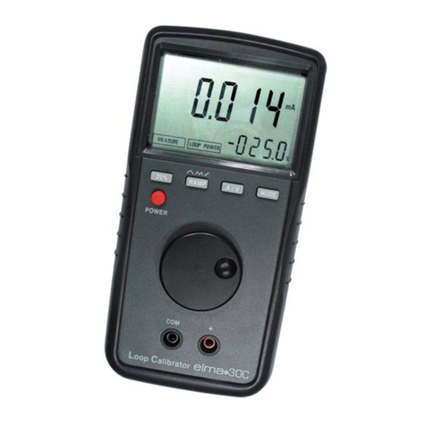
SHN-CAL is a 2-wre transmitter simulation tester and source (mA) calibrator.
It is also a multi-functional analog calibrator equipped with functions for measurement of
mA Output, power supply and measurement of 2-wire transmitter, and Measurement of
DC voltage for checking of loop power.
▷ Compact and light weight for each carrying.
▷ Proud of high accuracy of ±0.03% using high performance and high accuracy 16bit
A/D converter. (±0.01mA error at 4~20mA)
▷ Long time service with built-in Li-Polymer battery.
(Max. 13 hours on +24Vdc 20mA output)
▷ Fast switching with a slide switch.
▷ Indicating 0~25mA or -25.0~125.0% with 4-digit display.
■ This function is used to supply 0.00 ~ 24.00mA Output.
Check operation of your mA receiver with DC 24V output voltage.
1) Draw out one input wire from the instrument to be calibrated.
2) Move the central slide switch to mA or % and the right slide switch to
Source.
3) Connect (+) input of the instrument to a red source line of the calibrator and (-)
input to a black source line.
4) Turn the nob to adjust output current.
2. Read mA (+24Vdc Powered Measure) Mode
■ This function is used to measure the output current from the transmitter by
supplying +24Vdc.
1) Draw out output wires from the instrument to be calibrated.
2) Press +24Vdc powered S/W with slide switches at Source mA Output Mode.
(+24V LED On)
3) Connect Red wire (+) and Bl ack w i re (-) of t he calibrator to + a nd – of
the Output, r espectively.
4) Check if the current is put out within a range of 0.00~45.00mA.
3. Read mA (Current Measurement) Mode
■ This function is used to measure 0.00 ~ 45.00mA or -25.0~260.0%.
1) Connect one current loop of convenient part of the signal line.
2) Move the central slide switch to mA or % and the right slide switch to
Read.
3) Connect Red wire (+) and Bl ack w i re (-) of t he calibrator to + a nd –
of t he Output , respec tively.
4) Check if the current is put out within a range 0.00~55.00mA.
② Display Selector Switch (%, mA, Vdc)
③ Output Selector Switch (20mA, ADJ,
4mA)
4. Read Vdc (Voltage Measurement) Mode
■ This function is used to measure 0.00~+70.00Vdc.
④ +24Vdc Powered Measure S/W
1) Move the central slide switch to mA or % and the right slide switch to
Read.
2) Connect R ed wire (+) of the calibrator to + and Black wire (-) to –
pole of the voltage t o be measured. It is able to measure voltage to a
range of 0~70.00V.
3) When signal voltage of the loop power supply receiver exceeds DC 100V,
the internal fuse is disconnected
.
⑤ In/Out Terminals (Cautious on Polarity
of Outpts)
5. 2-Wire Transmitter Simulation Test
■ This function is used to simulate a test for 0.00 ~ 24.00mA output from 2-Wire
transmitter.
- +24V : Loop Powered Measure Mode
Output Mode for LED OFF
Measurement Mode for LED
ON
1) Disconnect and loose one or both inputs from the instrument to be
calibrated.
2)
Move the central slide switch to mA or % and the right slide switch to
2-Wire.
3) Connect Red wire (+) and Bl ack w i re (-) of t he calibrator to + a nd –
of t he Output , respec tively.
4) Turn the nob to adjust output current.
- CHG : Charging Check Lamp
Being Charged for LED ON
Charging Completed for LED
OFF
⑨ Output 4~20mA Variable Volume
For other problems than described above, please contact our head office .
※ Excessive switch operation may result in failure of the
product.
Address : 5
th
F/L, Shinho System Bldg. 20, Jomaruro 385 bungil, Bucheon -si, Gyeonggi -do
TEL : 032 -582 -3535 FAX : 03 2-582 -3674
