Leader Electronics Corp. LTC-906 User manual

LEADER ELECTRONICS CORP.
2-6-33 TSUNASHIMA-HIGASHI. KOHOKU-KU,
YOKOHAMA. JAPAN.
LEADER INSTRUMENTS CORP.
HEAD OFFICE
151 DUPONT ST.. PLAINVIEW. N.Y. 11803 U.S.A,
(516) 822-9300
)
J
I
MODEL LTC-906
>TRANSISTOR CHECKER
INSTRUCTION MANUAL
LEADER ELECTRONICS CORPORATION
77110.8K® Printed in Japan,
LTC-906 TRANSISTOR CHECKER
OPERATING INSTRUCTIONS
1. General
1.1 Transistor checker LTC-906
The LTC-906 is atransistor tester which is capable of determining
good/bad of transistor, FET, UJT, diode, etc. and also perfoming
automatic determination of the proper leads in-circuit and
out-of-circuit. This tester is also capable of DC parameter
measuring transistor and diode out-of-circuit.
1.2 Features
a. Auto-measurement which automatically scans electrode.
Electrode change-over by switch is not required.
b. Automatic determination Good/Bad of specimen.
c. Automatic identification of the lead configuration.
d. Both transistor and diode can be measured.
e. Audible indication of test result. This permits the operator
to pay his attention to the end of probe.
f. Drive power can be selected either at LOW/HIGH.
g. In measuring VgE transistor and Vj) of diode, Silicon
type and Germanium type can be distinguished.
h. Leak current of transistor and diode can be measured.
i. hpE of transistor can be measured.
j. 2way power supply system of internal battery/ external
power supply.
2. Specifications
2.1 Auto-test
AUTO-test can be accomplished both in-circuit and out-of-circuit
1
operation.
a. Semiconductors which can be tested
Bipolar transistor, J-FET, MOS-FET, UJT, SCR, Diode
b. Item of test
GOOD/BAD
Polarity (PNP/NPN, PCHANNEL/N CHANNEL)
Base/Collector of transistor
Gate/Drain of FET
Cathode/Anode of diode
c. Measurement mode
Transistor and diode
d. Measurement voltage
Approx. ±2V, duty ratio about 10%
e. Measurement current
LOW DRIVE ... Maximum 4.5mA, average 0.45mA
HIGH DRIVE ... Maximum 60mA, average 6mA,
f. Measurement speed 1-10 times/second
g. Display
Light emitting diodes and sound by buzzer
2.2
EX2 parameter measurement
Out-of-circuit operation alone. VbE> ICEO ^FE of bipolar
transistor and Vg and LEAK of diode are indicated by meter.
a. Measurement mode
Transistor and diode
b. Polarity to be measured
PNP and NPN transistors and forward and backward diodes
c. Measuring range
^D’ ^BE 0—3Vdc 1range. Accuracy ±6% of FS
2

LEAK, IcEO O-IOOaiA, 0-1,000juA, 0-10,000mA
3ranges Accuracy ±6% of FS
hpE 0—100, 0—1,000, 0—10,000 3ranges
Accuracy ±20%
d. Measuring current
Vd> VbE Maximum 2mA
hpE Base current ±ljuA
Collector current Maximum 30mA
e. Measuring voltage Maximum ±5V
2.3 Power supply
Internal battery Standard 9-volt transistor radio battery
(EVEREADY 216,
MALLORY MN1604)
External DC 8—lOV, 25mA
2.4 Diemsion and weight
152(H) XIIO(W) X60(D) mm (excluding handle)
About 0.4 kg.
2.5 Accessory
3-lead test cable 1 ea.
2.6 Options
AC adapter LPS-169A DC9V, 25mA
In-circuit probe LP-11
3
LTC-906
FUNCTIONAL
BLOCK
DIAGRAM

4. Description of panel
4.1 General
The front panel of LTC-906 is divided into three functional
sections, upper, middle and lower as shown in Fig. 4.1.
In the middle portion of the panel, those functions which are
related to all types of test are concentrated.® -®. In the lower
portion painted in brown, functions which are related to auto-test
of good or bad of transistor and leads identification are installed
®- @•
In the upper portion of the panel painted in green, functions
which are related to DC parameter test of bipolar transistor and
diode are concentratedly installed. ®-®.
(D AUTO/DC PARAMETER selector
-
@TRANSISTOR/DIODE selector-
®POWER switch —
®Test socket—
®External power jack
@Handle
(Q) Meter
(g) Meter-zero adjuster
©RANGE selector
51 POLARITY selector
5^ METER selector
5|i Mounting screw
®DRIVE level
®COLLECTOR/DRAIN indicator
(g) BASE/GATE indicator
(f) GOOD/BAD indicator
•® BUZZER
BUZZER switch
Fig. 4.1 Front Panel of LTC-906
5
4.2 Description of each functional section
A. Middle section
®POWER switch
This is aslide switch with 3positions for turning power on or off.
When the switch is slid to the left, power is turned off, at the
middle position battery can be checked, and at the right, power is
turned on.
Under battery check condition, the meter indicates whether the
voltage of abattery in operative condition or that of external
power supply is within aproper range or not.
@TRANSISTOR/DIODE selector
This is aslide switch with 2positions for setting the tester’s test
mode either to transistor or diode.
Test mode is set at transistor when the knob is slid to the left and
at diode when at the right.
@AUTO/DC PARAMETER selector
This is aslide switch with 2positions for setting the tester’s test
mode either to Auto-test for judging good/bad of transistor and
diode and identifying the proper leads, or DC PARAMETER test
for measuring forward voltage, leak current and current
amplification ratio. Test mode is set at Auto-test when the knob
is slid to the left and at DC parameter test when at the right.
®Test socket
This is asocket into which atransistor or diode to be tested is
inserted. In the case of in-circuit test, aplug of test lead is
connected to this socket.
The socket has 3contacts divided into upper, middle and lower,
and they are numbered from upper in sequence as 1, 2and 3for
identification. In addition to numbers, these are also identified by
color for matching with test leads as follows:
6
upper -1-Blue
Middle -2-Green
Lower -3-Yellow
In case adiode is tested, the middle contact is not used, and
1-blue and 3-yellow contacts are used.
Lower section
The following function units from reference numeral 5to
10 become effective in the case of AUTO-test mode, and
they are irrelevant to DC PARAMETER test:
DRIVE power
This is aslide switch with 2positions for select-test current,
HIGH or LOW, in the case of AUTO-test.
The power of test current is set at LOW when the knob is slide
down, and on the contrary, it is set at HIGH when slid upward.
BUZZER switch
This is aslide switch with 2positions for turning buzzer function
on or off. The buzzer is turned on as the knob is slid upward, and
on the contrary it is turned off when slid downward.
Buzzer
This buzzer (small speaker) generates sounds when atransistor or
diode under test is in good condition in the case of AUTO-test.
When this function is not required, it can be turned off.
GOOD/BAD indicator
This indicator consists of 3LEDs which indicate good/bad of a
transistor or diode under test, PNP or NPN of transistor and the
polarity of diode in the case of AUTO-test.
BASE/GATE indicator
This indicator consists of 3LEDs which indicate which one of the
3contacts of the test socket acontrol electrode such as the base
of abipolar transistor, and the gate of afield-effect transistor is
connected to in the case of AUTO-test of transistor. Only when
the transistor under test is in good condition, one of those LEDs
corresponding to the base is lighted.
@COLLECOT/DRAIN indicator
Like the base/gate indicator, this consists of 3LED which
indicate collector of bipolar transistor or drain of field-effect
transistor in the case of AUTO-test of transistor. In case of
transistor under test is good in quality, one or two LEDs
corresponding to the contacts of the socket are lighted.
C. Upper section
The following function units from reference numeral (U)to
@become effective only in the case of DC PARAMETER
test of bipolar transistor and diode, and they are irrelevant
to AUTO-test:
(U) POLARITY selector
This is aslide switch with 2positions for setting LTC-906 to
conform with the polarity of atransistor or diode when it is DC
PARAMETER test.
In case aPNP transistor or adiode of which cathode is at contact
1 side of the socket is tested, the knob is slid to the left, and in
case an NPN transistor or adiode of which cathode is at contact 3
side is tested, the knob is slid to the right.
®METER selector
This is aslide switch with 3positions for selecting aproper meter
display at the time of DC PARAMETER test. At the time of
transistor test mode, the meter indicates Vbe, the voltage in
forward direction between base and emitter when the knob is slid
to the right, ICEO> collector leak current with base open when it
is set at medium position and hpE) DC current amplification ratio
when it is slid to the left.
At the time of diode test mode, the meter indicates Vp), the

voltage in forward direction, when the knob is slid to the right,
and indicates leak current in the reverse direction, LEAK when it
is set at medium position. In the case of diode test, the left
position of this meter selector has no fiinction.
RANGE selector
This is aslide switch with 3contact points for selecting one of
three meter scale magnification ratios, xl, xlO or xlOO, to
indicate hpE ICEO transistor and LEAK of diode at the
time of DC PARAMETER test.
Its ratio is set at xl when the knob is slid to the left, and at xlO
when it is set at medium position and at xlOO when the knob is
slid to the right. The magnification ratio for Vbe and Vj) is xl
regardless the range selector.
Meter
This is aDC ammeter for indicating hpE> ICEO VgE ^
transistor and LEAK and Vp) of adiode in the case of DC
PARAMETER test. When the power switch is at the battery
check position, the meter indicates whether the voltage of battery
in operative condition or that of external power supply is within
proper range or not regardless the position of other switches.
Meter-zero adjuster
This mechanically adjusts the meter needle to zero. When the
power switch is off, adjust the meter needle to zero by rotating
the screw.
Other parts
External power jack
This is an external power jack to which external DC power supply
of DC9V can be connected. AC adapter, LPS-169A is fitted to
this jack.
Handle
-9-
@Mounting screw
The battery compartment can be opened by loosening 2
mounting screws located at left and right when abattery is
replaced.
5. Operation of LTC-906
5.1 General
5.1.1 For safety
In making atest of an electronic apparatus, it involves arisk in
many cases. There is apossibility that ahigh voltage is being
generated at unexpected parts in the equipment which is out of
order. Please pay attention to the following points:
(1) The power switch of an apparatus to be tested should be
turned off and apower supply cord should be disconnected
from AC oudet when atest lead is connected or
disconnected from the apparatus. If this is impractical do
not touch metal portions of such an apparatus and work
should be performed on the floor of good insulation to
reduce the influence of electric shock.
(2) Electric charge of filter capacitors should be discharged
before connecting atest cord to the apparatus. Such a
condenser may be fuUy charged up to adangerous degree.
(3) It is necessary to keep atest instrument in good condition.
Atest lead which is partly broken or its covering is partially
missing may accidentally come to contact with adangerous
potential.
(4) Upon completion of test, the test leads should be
immediately disconnected from an apparatus.
5.1.2 Replacement of battery
The LTC-906 can be operated on one unit of astandard 9volt
transister radio battery. Prior to operating the checker, anew
battery must be installed as it has no battery installed. Abattery
-10 -
can be mounted by the following procedures. Replacement of
battery after 2nd time can be accomplished in the same manner.
(1) Be sure to turn the power switch off. This is important. If
this is neglected, the LTC-906 may be damaged by an
unexpected accident such as inverted connection or
shortcircuit of abattery.
(2) Loosen the 2 screws at the left and right of battery case
with ascrew driver and remove the case.
(3) if an old battery is mounted, remove it from abattery
holder located at the bottom of case, and then disconnect
from abattery snap connected to the main unit of checker.
(4) Connect anew battery with proper polarity set to the
battery snap and set the battery in the battery holder at the
bottom of case.
(5) Place the case in the checker with care exercised not apply
undue force to printed circuit board and lead wire of
battery snap and fix it with 2screws.
5.1.3 Battery check
Tile voltage of abattery required to have LTC-906 perform
correct operation is 7V or larger. If the battery voltage decreases,
the proper operation of LTC-906 will be hampered.
When the power switch is set at battery check position, the meter
indicates the range of battery voltage under an optional operation
condition of LTC-906 (or the voltage of an external DC power
source when used.).
The battery is in good condition if the meter needle is within the
range of GOOD of the battery scale, and it must be replaced with
anew one if the needle indicates the range of REPLACE.
The terminal voltage of abattery becomes smaller in inverse
proportion to its current due to voltage decrease of internal
-11 -
resistance even if its internal electromotive force is the same.
Consequently, the battery voltage of LTC-906 when it is in such
operational condition in which alarge battery current is being
consumed becomes lower than that of such acase in which a
small current is being consumed.
Acurrent being consumed by LTC-906 under no load;
DC PARAMETER test About 2mA at 9V
AUTOtest About 15 mA at 9V.
When aload is connected, its power consumption is further
increased, and it may exceed 30mA depend on the type of load
and way of connection.
As aforementioned, the battery current^ of LTC-906 varies
considerably depend on its operative condition, and its operation
time is fairly long as much as several tens hours if its current is
small, and on the contrary it becomes shorter less than one hour
if its current is large.
In order to use the battery economically and lengthen its life,
measurement should be carried out quickly as short as possible
and the power switch should be turned off upon completion of
measurement.
5.1.4 External DC power supply
The LTC-906 can be operated by external DC power supply
which is 7to lOV and more than 25mA connected to the
external power source jack. The outer circumference of the jack
is positive and its internal pin is negative in polarity. The
LTC-906 may be damaged if an external power source is
inadvertently connected inverse position.
As an external power source suitable for the LTC-906, AC
adapter type LPS-169A (option) is available.
LPS-169A Input AC 50/60Hz 100-120V 4.5VA
Output DC 9A 25mA
-12 -

In case the checker is used for along time, it will be economical
to utilize AC adapter than battery operation which require
battery replacement.
5.1.5 Other prec autions
(1) Aused-up battery may g^ve bad influence to the LTC-906
by its leaked battery liquid, therefore, such abattery
should be immediately removed from the checker. By the
same reason, abattery should be kept removed when the
checker is not used for along time.
(2) It is dangerous to cause abattery to short or to throw it
into fire.
(3) When the LTC-906 is carried, its power switch should be
kept off regardless the presence or absence of abattery.
With the power switch set at off position, the moving coil
of the meter is made short, and by its brake action, adverse
influence of mechanical shock while in transit to the meter
will be reduced.
(4) The LTC-906 should be carefully handled not to give strong
mechanical shock.
(5) Please do not place the checker near afire or leave it inside
acar under the blazing sun. Plastic portion may be
deformed by heat.
(6) Do not use solvent such as alcohol, theinner, benzine, etc.
for cleaning the checker. These solvents may dissolve the
paint or plastics of the checker.
The checker should be cleaned with aslighdy wet cloth.
5.2 Auto-test
The LTC-906 is capable of making in-circuit and out-of-circuit
test of bipolar transistor, field-effect transistor (FET), SCR, UJT,
diode, etc.
For AUTO-test, there are 2modes of transistor and diode which
can be selected by the TRANSISTOR/DIODE selector.
The AUTO-test unit automatically scans test signal being
impressed to the electrode of asemiconductor to be measured
and determines whether it is good or bad, and identifies the
electrode, if it is good, and causes LEDs to display its results.
Together with LED display, the result of test is notified by the
sound of abuzzer (small speaker) when asemiconductor^ good
in quality. Consequendy, the operator can concentrate his
attention to perform testing without looking at the display panel
for confirming the result of each test, and it is possible to
perform efficient in-circuit test.
When this buzzer sound is not required, this founction is turned
off by the buzzer switch.
For making in-circuit test, connect the plug of the attached test
lead to the test socket iwith its lead wires adjusted to
corresponding colors displayed on the panel, and then connect its
clip to atransistor of diode to be measured.
When an in<ircuit probe Model LP-11, an option, is used being
connected to the end of the test lead, semiconductors installed on
the printed circuit board can be easily measured as the probe’s tip
can be freely moved depend on the arrangement of legs of such
semiconductors.
The attached test lead should be used when atransistor or diode
cannot be directly inserted into the test socket for out-of-circuit
test.
Caution for in-circuit test
(1) Prior to connecting the test clip or probe to an circuit
under test, be sure to turn the power switch of the circuit
off and cause electric charge accumulated in the capacitores
to completely discharge through aresistor of several tens
-13 --14 -

ohms.
The LTC-906 may be damaged if avoltage of more than
±5V is externally applied to it.
(2)
Upon completion of test, the test clip of LTC-906 should
be disconnected from the circuit before its power switch is
turned on.
5.2.1 Transistor auto-test
(1) Set the AUTO/DC PARAMETER select at AUTO.
(2) Set the TRANSISTOR/DIODE selector at TRANSISTOR.
(3) Turn the power switch on.
(4) Turn the BUZZER switch on when audible GOOD signal is
desired. Keep it off if not so desired.
(5) Set the drive level at LOW.
(6) Insert atransistor directly into the test socket (out-of-
circuit). Or, connect 3clips of test lead coming from the
test socket or 3tips of test probe to the 3legs of a
transistor to be measured. Connection of electrode must
continue more than 2seconds.
(7) The GOOD/BAD indicator should display GOOD signal if
the transistor is good, if aGOOD LED located at upper
flashes, the transistor is of PNP or Pchannel, and on the
contrary the lower GOOD LED flashes, it is on NPN or N
channel. At the same time, LEDs of the base/gate indicator
and collector/drain indicator flash and the electrode of the
transistor corresponding to test leads can be identified. If
the buzzer switch is on, intermittent sounds are generated.
(8) If the BAD display LED is kept lighted (the buzzer does
not generate sound), the transistor is bad or drive level is
inadequate due to aheavy load in the circuit around the
transistor.
(9) Change-over the drive level to HIGH and repeat test from
(6) to (8) in the case of the in-circuit test.
(10) If it is judged as BAD again, the transistor is bad or drive
level is still inadequate.
(11) In the case of in-circuit test, disconnect the transistor wdiich
has been judged as BAD by the step (10) from the circuit,
and test it again by out-of-circuit AUTO-test at LOW and
HIGH drive level.
if the transistor is judged as BAD at both LOW and HIGH
drive level, it should be short-circuit, broken or
deteriorated. If transistor is of bipolar type, perform DC
PARAMETER test described in Par. 5.3.1 to make sure it
is really bad or not.
(12) To test another transistor, return to Step (5).
(13) Identification of leads
a. Bipolar transistor/ FET
When the base bipolar transistor and field-effect
transistor of MOS type or junction type are in good
condition, one of the three LED of the base/gate
indicator corresponding to contacts 1to 3of the test
socket flashes.
Similarly, when the collector of bipolar transistor or
the drain of FET is in good condition, a
corresponding LED of the collector/drain indicator
flashes. In this case, the collector/drain indicator
displays one electrode excluding base, or 2electrodes
at the same time. The reason why it displays 2
electrodes simultaneously is that the collector and
emitter of abipolar transistor and the drain and
source of an FET have amplification function even if
-15 —-16 -
they are exchanged. Especially, the drain and source
of junction type FET have aperfect symmetry in
many cases.
In the case of out-of-circuit, the collector/drain
indicator frequendy displays 2LEDs at the same
time, and in the case of in-circuit test, it displays 1or
2depend on the condition of circuits.
In order to identify the emitter and collector, cannot
be identified by AUTO-test, of abipolar transistor,
hpE of the transistor is measured by DC PARA-
METER test. From agenerally known fact that hpg
of such atransistor becomes lower than that of
normal operation when its collector is caused to
operate as emitter, the collector and emitter of a
bipolar transistor can be distinguished,
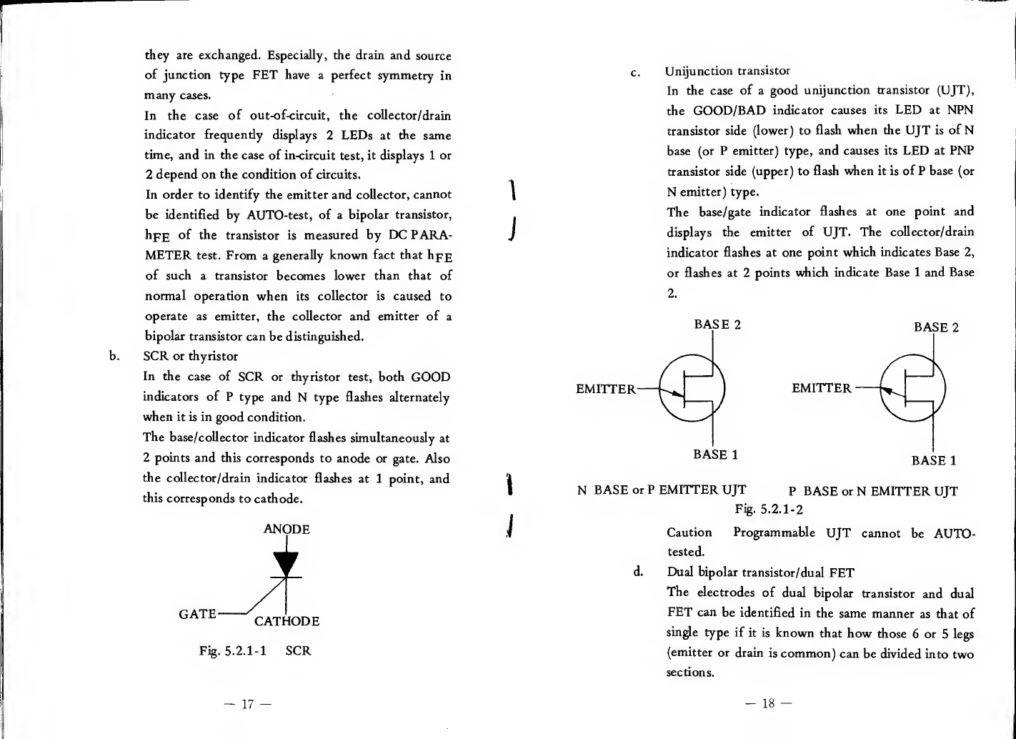
b. SCR or thyristor
In the case of SCR or thyristor test, both GOOD
indicators of Ptype and Ntype flashes alternately
when it is in good condition.
The base/collector indicator flashes simultaneously at
2points and this corresponds to anode or gate. Also
the codector/drain indicator flashes at 1point, and
this corresponds to cathode.
Fig. 5.2.1-1 SCR
-17 -
1
J
1
i
c. Unijunction transistor
In the case of agood unijunction transistor (UJT),
the GOOD/BAD indicator causes its LED at NPN
transistor side (lower) to flash when the UJT is of N
base (or Pemitter) type, and causes its LED at PNP
transistor side (upper) to flash when it is of Pbase (or
Nemitter) type.
The base/gate indicator flashes at one point and
displays the emitter of UJT. The collector/drain
indicator flashes at one point which indicates Base 2,
or flashes at 2points which indicate Base 1and Base
2.
NBASE or PEMITTER UJT pBASE or NEMITTER UJT
Fig. 5.2.1-2
Caution Programmable UJT cannot be AUTO-
tested.
d. Dual bipolar transistor/dual FET
The electrodes of dual bipolar transistor and dual
FET can be identified in the same manner as that of
single type if it is known that how those 6or 5legs
(emitter or drain is common) can be divided into two
sections.
-18 -
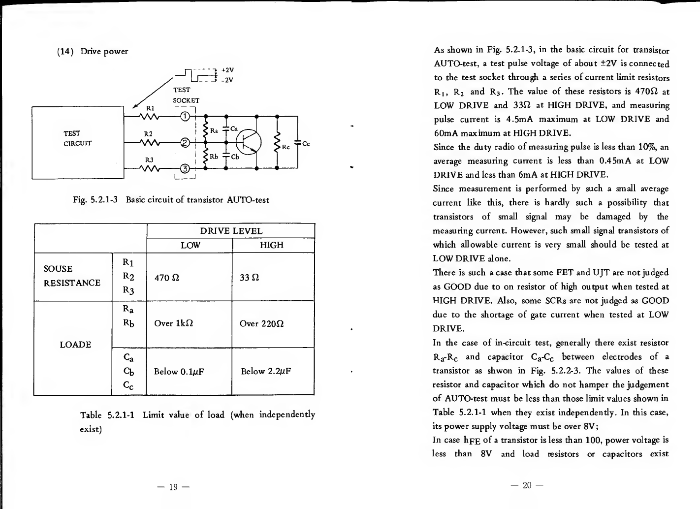
(14) Drive power
Fig. 5.2.1-3 Basic circuit of transistor AUTO-test
DRIVE LEVEL
LOW HIGH
SOUSE
RESISTANCE
Rl
R2
R3 470 n33
LOADE
Ra
Rb Over Ikn Over 220f2
Ca
Cb
Cc
Below 0.1/iF Below 2.2mF
Table 5. 2. 1-1 Limit value of load (when independently
exist)
As shown in Fig. 5.2. 1-3, in the basic circuit for transistor
AUTO-test, atest pulse voltage of about ±2V is connected
to the test socket through aseries of current limit resistors
Ri, Rj and R3.The value of these resistors is 470S2 at
LOW DRIVE and 33f2 at HIGH DRIVE, and measuring
pulse current is 4.5mA maximum at LOW DRIVE and
60mA maximum at HIGH DRIVE.
Since the duty radio of measuring pulse is less than 10%, an
average measuring current is less than 0.45mA at LOW
DRIVE and less than 6mA at HIGH DRIVE.
Since measurement is performed by such asmall average
current like this, there is hardly such apossibility that
transistors of small signal may be damaged by the
measuring current. However, such small signal transistors of
which allowable current is very small should be tested at
LOW DRIVE alone.
There is such acase that some FET and UJT are not judged
as GOOD due to on resistor of high output when tested at
HIGH DRIVE. Also, some SCRs are not judged as GOOD
due to the shortage of gate current when tested at LOW
DRIVE.
In the case of in-circuit test, generally there exist resistor
Rj-Rc and capacitor C^-Cc between electrodes of a
transistor as shwon in Fig. 5.2. 2-3. The values of these
resistor and capacitor which do not hamper the judgement
of AUTO-test must be less than those limit values shown in
Table 5. 2.1-1 when they exist independently. In this case,
its power supply voltage must be over 8V
;
In case hpE of atransistor is less than 100, power voltage is
less than 8Vand load resistors or capacitors exist
-19 --20 -
simultaneously more than 2, the value of allowable load
resistance will be larger than those shown in the table and
the value of capacitor will be smaller.
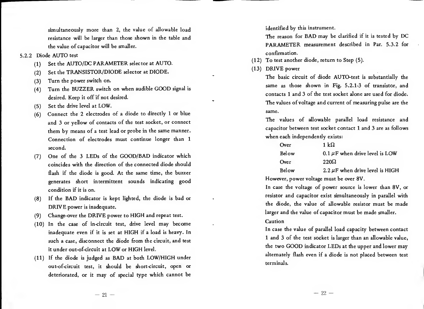
5.2.2 Diode AUTO test
(1) Set the AUTO/DC PARAMETER selector at AUTO.
(2) Set the TRANSISTOR/DIODE selector at DIODE.
(3) Turn the power switch on.
(4) Turn the BUZZER switch on when audible GOOD signal is
desired. Keep it off if not desired.
(5) Set the drive level at LOW.
(6) Connect the 2electrodes of adiode to directly 1or blue
and 3or yellow of contacts of the test socket, or connect
them by means of atest lead or probe in the same manner.
Connection of electrodes must continue longer than 1
second.
(7) One of the 3LEDs of the GOOD/BAD indicator which
coincides with the direction of the connected diode should
flash if the diode is good. At the same time, the buzzer
generates short intermittent sounds indicating good
condition if it is on.
(8) If the BAD indicator is kept lighted, the diode is bad or
DRIVE power is inadequate.
(9) Change-over the DRIVE power to HIGH and repeat test.
(10) In the case of in-circuit test, drive level may become
inadequate even if it is set at HIGH if aload is heavy. In
such acase, disconnect the diode from the circuit, and test
it under out-of-circuit at LOW or HIGH level.
(11) If the diode is judged as BAD at both LOW/HIGH under
out-ofcircuit test, it should be short-circuit, open or
deteriorated, or it may of special type which cannot be
identified by this instrument.
The reason for BAD may be clarified if it is tested by DC
PARAMETER measurement described in Par. 5.3.2 for
confirmation.
(12) To test another diode, return to Step (5).
(13) DRIVE power
The basic circuit of diode AUTO-test is substantially the
same as those shown in Fig. 5. 2. 1-3 of transistor, and
contacts 1and 3of the test socket alone are used for diode.
The values of voltage and current of measuring pulse are the
same.
The values of allowable parallel load resistance and
capacitor between test socket contact 1and 3are as follows
when each independently exists:
Over 1kf2
Below 0.1 juF when drive level is LOW
Over 220f2
Below 2.2 jUF when drive level is HIGH
However, power voltage must be over 8V.
In case the voltage of power source is lower than 8V, or
resistor and capacitor exist simultaneously in parallel with
the diode, the value of allowable resistor must be made
larger and the value of capacitor must be made smaller.
Caution
In case the value of parallel load capacity between contact
1and 3of the test socket is larger than an allowable value,
the two GOOD indicator LEDs at the upper and lower may
alternately flash even if adiode is not placed between test
terminals.
-21 -—22 —
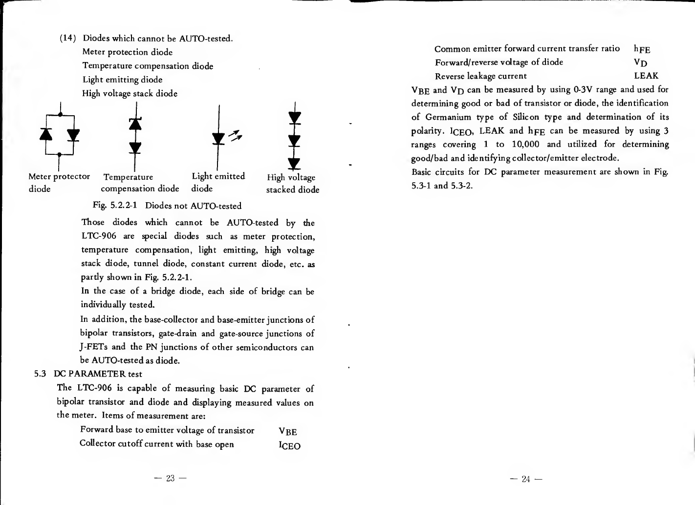
(14) Diodes which cannot be AUTO-tested.
Meter protection diode
Temperature compensation diode
Light emitting diode
High voltage stack diode
Meter protector Temperature Light emitted High voltage
diode compensation diode diode stacked diode
Fig. 5. 2.2-1 Diodes not AUTO-tested
Those diodes which cannot be AUTO-tested by the
LTC-906 are fecial diodes such as meter protection,
temperature compensation, light emitting, high voltage
stack diode, tunnel diode, constant current diode, etc. as
pardy shown in Fig. 5.2. 2-1.
In the case of abridge diode, each side of bridge can be
individually tested.
In addition, the base-collector and base-emitter junctions of
bipolar transistors, gate-drain and gate-source junctions of
J-FETs and the PN junctions of other semiconductors can
be AUTO-tested as diode.
5.3 DC PARAMETER test
The LTC-906 is capable of measuring basic EXH parameter of
bipolar transistor and diode and displaying measured values on
the meter. Items of measurement are:
Forward base to emitter voltage of transistor VgE
Collector cutoff current with base open ICEO
Common emitter forward current transfer ratio hpg
Forward/reverse voltage of diode Vj)
Reverse leakage current LEAK
Vbe and Vj) can be measured by using 0-3V range and used for
determining good or bad of transistor or diode, the identification
of Germanium type of Silicon type and determination of its
polarity. ICEO> LEAK and hpE can be measured by using 3
ranges covering 1to 10,000 and utilized for determining
good/bad and identifying collector/emitter electrode.
Basic circuits for DC parameter measurement are shown in Fig.
5.3-1 and 5.3-2.
—23 —-24 —
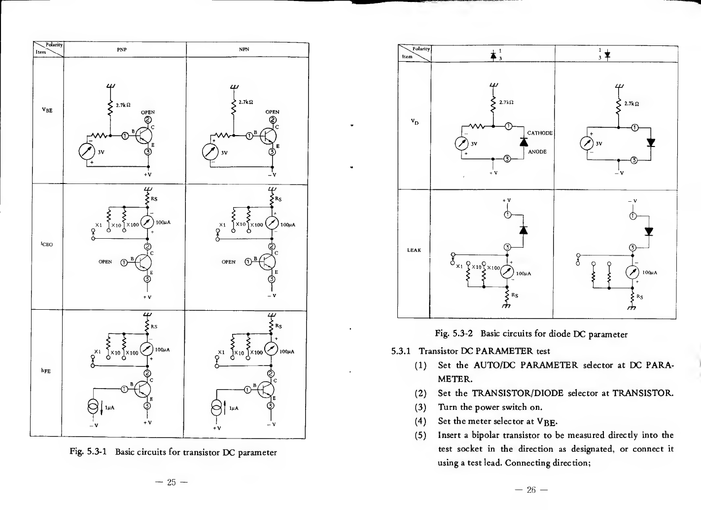
Fig. 5.3-1 Basic circuits for transistor DC parameter
!,7kn
Fig. 5.3-2 Basic circuits for diode DC parameter
5.3.1 Transistor DC PARAMETER test
(1) Set the AUTO/DC PARAMETER selector at DC PARA-
METER.
(2) Set the TRANSISTOR/DIODE selector at TRANSISTOR.
(3) Turn the power switch on.
(4) Set the meter selector at VgE-
(5) Insert abipolar transistor to be measured directly into the
test socket in the direction as designated, or connect it
using atest lead. Connecting direction;
Socket contact Electrode
1/blue Base
2/green Collector
3/yellow Emitter
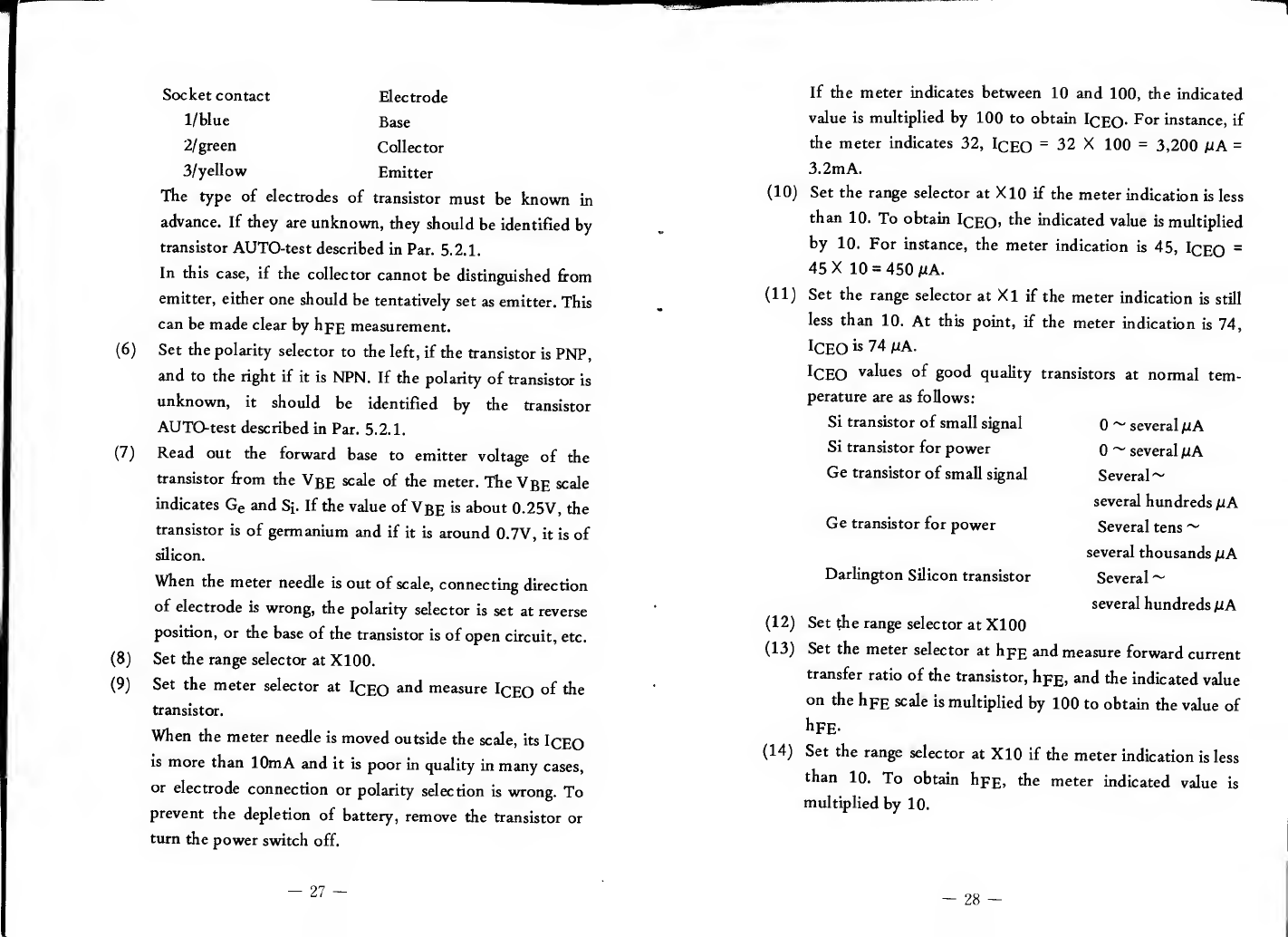
The type of electrodes of transistor must be known in
advance. If they are unknown, they should be identified by
transistor AUTO-test described in Par. 5.2.1.
In this case, if the collector cannot be distinguished from
emitter, either one should be tentatively set as emitter. This
can be made clear by hpg measurement.
(6) Set the polarity selector to the left, if the transistor is PNP,
and to the right if it is NPN. If the polarity of transistor is
unknown, it should be identified by the transistor
AUTO-test described in Par. 5.2.1.
(7) Read out the forward base to emitter voltage of the
transistor from the Vbe scale of the meter. The VgE scale
indicates Ge and Sj. If the value of VgE is about 0.25V, the
transistor is of germanium and if it is around 0.7V, it is of
silicon.
When the meter needle is out of scale, connecting direction
of electrode is wrong, the polarity selector is set at reverse
position, or the base of the transistor is of open circuit, etc.
(8) Set the range selector at XI00.
(9) Set the meter selector at ICEO measure ICEO of 'll®
transistor.
When the meter needle is moved outside the scale, its ICEO
is more than 10mA and it is poor in quality in many cases,
or electrode connection or polarity selection is wrong. To
prevent the depletion of battery, remove the transistor or
turn the power switch off.
-27 —
If the meter indicates between 10 and 100, the indicated
value is multiplied by 100 to obtain ICEO- For instance, if
the meter indicates 32, IcEO =32 X100 =3,200 /tA =
3.2mA.
(10) Set the range selector at X10 if the meter indication is less
than 10. To obtain ICEO> indicated value is multiplied
by 10. For instance, the meter indication is 45, IcEO =
45 X10 =450 M.
(11) Set the range selector at Xl if the meter indication is still
less than 10. At this point, if the meter indication is 74,
ICEO is 74 iJiA.
ICEO values of good quality transistors at normal tem-
perature are as follows:
Si transistor of small signal 0~several /l/A
Si transistor for power 0~several jiA
Ge transistor of small signal Several ~
several hundreds /tA
Ge transistor for power Several tens
several thousands fxA
Darlington Silicon transistor Several ~
several hundreds fiA
(12) Set the range selector at XlOO
(13) Set the meter selector at hpg and measure forward current
transfer ratio of the transistor, hpg, and the indicated value
on the hpE scale is multiplied by 100 to obtain the value of
hpE.
(1^) Set the range selector at XIO if the meter indication is less
than 10. To obtain hpp, the meter indicated value is
multiplied by 10.
-28 -

(15) Set the range selector at XI if the meter indication is still
less than 10. For instance, if the meter indication is 70, its
hpE =70.
The LTC-906 is capable of measuring hpE in 3ranges up to
10,000, and these values cannot be regarded as the same as
those listed in the data book due to different measuring
conditions.
Measured values by this instrument are between several tens
and several hundreds for ordinary small signal transistor and
between several hundreds and several thousands for
Darlington transistor.
In the case of apower transistor of which hpg depends on
collector current, its hpp is shown with afairly small value
(less than 100) since measurement is done by avery small
base current of 1flA.
(16) Distinction of collector and emitter
In case the collector and emitter of atransistor are
unknown, they can be distinguished by the difference in
hpg. The value of hpg of atransistor when it is connected
inverse direction with its emitter assumed as collector is
decreased to 50 to 5% of that of hpp to be obtained by
normal connection.
When atransistor is unknown about its collector and
emitter, its hpp is measured with one of the two electrodes
other than the base tentatively assumed as emitter and the
other as collector. Again, hpp is measured with those
electrodes exchanged. One of these two cases in which is
larger hpp has been obtained shows the correct connection
of the transistor.
(17)
Correction of hpp
By the hpp measuring method of LTC-906, an apparent
hpp is indicated larger than the tme hpp due to Ip;pQ
especially in the case of agermanium transistor.
Atrue hpp can be easily obtained by deducting l^pQ
shown by the unit of fiA from ameasured value of hpp.
For instance, if ameasured value of hpp is 280 and Iq^q is
45mA, its true hpp will be; 280-45 =235.
(Note) When base current is Ip and collector current is
Ip,; the following relationship exists;
^C^'^FE^B *CEO (a)
^C “*CEO
II (b)
In the LTC-906, abase current of 1(lA is caused to flow
and collector current is measured by the unit of /nA,
therefore, the value of hpp can be direcdy read out as the
value of collector current from which the unit of nA is
eliminated by ignoring Ip;£Q, If bpp cannot be ignored, a
value which is obtained by deducting Iq£q from Iq will be
atrue hpp.
(18)
Calculation of IQpQ
The collector cutoff current with emitter open IpjgQ,
which is another EXi: parameter of transistor, can be
obtained by the following computation:
-29 —-30 -

^BO “^CEO
True hpg (c)
For instance, I(^gQ in the case of example (17) will be
45 mA
235 0.19 HA
(19) To start anew measurement, return to Step (4)
5.3.2 Diode DC PARAMETER test
(1) Set the AUTO/DC PARAMETER selector at EXD PARA-
METER’
(2) Set the TRANSISTOR/DIODE selector at DIODE.
(3) Turn the power switch on.
(4) Set the meter selector at Vq.
(5) Insert the two electrodes of adiode to be measured directly
into contact 1and 3of the test socket, or connect them by
using atest cable.
(6) Set the polarity selector in the same direction as that of the
connected diode if its polarity is known. If the polarity of
diode is unknown, it should be round out by the diode test
described in Par. 5.2.2, or it should be estimated from the
value of forward/reverse shown in (9).
(7) Read out the forward voltage of diode Vq from the Vq
scale of the meter. The meter needle is moved outside the
scale when adiode is not connected, connection is in
revsrse direction or it is made as open circuit.
(8) Set the polarity selector to the other side and read out the
value of Vj^ again. This value is areverse direction voltage
of the diode. In the case of diodes of which leak current is
small such as silicon diode, etc., the meter needle is moved
outside the scale in most cases when their reverse direction
voltage is measured.
(9) Distinction of polarity
Since the forward voltage of adiode is generally larger than
its reverse voltage, the polarity of adiode of which polarity
is unknown can be estimated by comparing its forward
voltage with its reverse voltage. In other words, the
connection is which the value of Vj^ is smaller than the
other is in forward, and at this time, it can be known from
the direction of diode displayed by the polarity selector
that the cathode of diode is connected to contact 1or 3of
the test switch. For instance, if the value of Vp is smaller
when the polarity selector is set at the lefr position, the
cathode electrode is connected to contact 1side of the test
switch.
(10) Identification of type of diode
The type of diode can be presumed by the amount of
forward voltage or reverse voltage as shown in Table
5. 3. 3-1. The scale of the meter indicates the
representative ranges of forward voltage to serve as
guideline to identify germanium and silicon diode.
(11) Set the polarity selector at the same direction as that of the
connected diode.
(12) Set the range selector at XIOO.
(13) Set the meter selector at LEAK and measure reverse leak
current of diode on the LEAK scale of the meter.
When the meter needle is moved outside the scale,
a. Setting of the polarity selector is reverse.
b. Leak current of diode is larger than 10mA.
—31 —-32 -

c. Diode is short-circuit
d. Diode is of special type such as meter protection,
tunnel, trigger, etc.
In such acase, immediately stop measurement to protect
the diode from damage and prevent the depletion of
battery and remove the diode or turn the power switch off.
If the meter indicates between 10 and 100 on the LEAK
scale, the indicated value is multiplied by 100 to obtain a
leak current, for instance, if the meter indication is 35, a
leak current =35 X100 =3,500 iiA =3.5mA.
(14) Set the range selector at XIO if the meter indication is less
than 10, and multiply the meter indication by 10. For
instance, if the meter indication is 85, leak current will be
85 X10= 850/xA.
(15) Set the range selector at XI if the meter indication is still
less than 10, and read out the meter indication.
For instance, if the meter needle indicates 15 on the LEAK
scale, its leak current is 15 fiA.
In the case of asilicon diode, its leak current is very small
at normal temperature, and the meter needle hardly moves
in many cases.
In the case of agermanium diode, it is between several and
several hundreds ^lA.
(16) To start anew measurement, return to Step (4).
(Note) At the time of diode DC parameter test, the left
hand side position of the meter selector does not
have any function.
Diode Forward
voltage (V)
Reverse
voltage (V)
Leak
current {(J-A)
Germanium small
signal
0.1 -0.5 1—full scale Several —Several 100
Germanium power 0.2 ~0.7 1—full scale Several 10 —
Several 1000
Silicon small signal 0.3-1 Full scale 0—Several 10
Silicon power 0.5 -1.5 Full scale 0—Several 100
Light emitting 1.5-3 Full scale 0—Several 10
Meter protection 0.2 -0.7 same as forward voltage
Zener 0.3-1 FuU scale 0—Several 100
Temperature com-
pensation Zener
Full scale Full scale 0—Several 10
(Caution) 1. The light emitting diode generates weak light when its
forward voltage is measured. In measuring aleak current,
the l^ht emitting diode emits strong light by alarge
forward current which is caused to flow by setting the
polarity switch in reverse.
2. The forward voltage of atemperature compensation
Zener diode becomes full scale as it is atemperature
compensation diode.
3. In the case of abridge diode, each side of the bridge can
be individually measured.
4. DC parameter can be measured by assuming PN junction
of base-collector and base-emitter of bipolar transistor
and gate-drain and gate-source of junction type FET as
diode. In this case, for measuring aleak current, if a
large forward current is caused to flow by mistake, such
acurrent may damage junctions.
—33 ——34 —

Battery +1—
^
006P TYPE -p
0106 }
\2SC372-0(
V^102 A
•T2SC372 -0
iR108.
*102 ,50k;
»-l>iA^
\ADjH
LJ^
6 6 66
Jt&BCHECK I
I1O9PJ05 50r,R1» 82K
has aa
I<Rit6^$i5e^isae
iiSLLZL
y»PO»iAADj t6-J? 66
o^.ES ;«o J~”^
ol; JU
0-T041 {2
/j)
LEADER ELECTRONICS CORP.
VIC303B
'BCD COUNTtR
>j IC305 h6_ Xc3I1
ii<i Vdecade counter /driver oT0X>IJ'
'•0'^ -V
VTO Tl 12 T3 MT5 T6 T7 TB TBCffrl ,,
13 12 f4 17 IK. h15 _I6 T9 mll2 LooEJ-^SmJ
|40^
220*^ '
fHian^L.3
Ss 3C313Dhl .2IC5t3A^li
4066] ]]406&P [
RSC^
“SsfrsRgF
220K .
™a9*vL
^iocrt/^ 1
)ic3a&^
R321 IM ^.J._ R322 lOOK *
v-wi-flh +V-W^h
Model LTC -906 0-104T(3/3 )
leader electronics CORP.

Other Leader Electronics Corp. Test Equipment manuals


