*1 Above code shows model number of driver only. Refer to outline drawings for model number of sensor and extension cable.
CALIBRATION JIS SCM440 flat surface SYSTEM CABLE LENGTH 5m or 9m
MATERIAL OPERATING Sensor : -40 to +125°C
MEASURING 3mm to 16.5mm from sensor tip TEMPERATURE Extension Cable : -40 to +125°C
RANGE RANGE Driver : -40 to +80°C
SENSITIVITY*2 0.8 V/mm RANGE OF TEMPERATURE EX4 : -20 to +85C(Sensor, Extension Cable & Driver)
SENSITIVITY ERROR*2 Within ±4% AT EXPLOSION PROOF EX5,B : -38 to +80C(Sensor, Extension Cable & Driver)
LINEARITY*2 Within ±200
m of 0.8V/mm straight line : CONSTRUCTION EXC : -30 to +80C(Sensor, Extension Cable & Driver)
(if calibrated as a system) TEMPERATURE Sensor : Less than ±3% of F.S.
Within ±270
m of 0.8V/mm straight line : CHARACTERISTIC Extension Cable : Less than ±3% of F.S.
(including interchangeability errors) Condition : Gap=14mm, Target : JIS SCM440
Linear range : 13.5mm 0 to 80°C (at 20°C standard)
FREQUENCY DC to 200 kHz or more(-3 dB) Driver : Less than ±3% of F.S.
RESPONCE*2 Loop : Less than ±4% of F.S.
MAX. OUTPUT Approx. -23VDC Condition : Gap=14mm, Target : JIS SCM440
VOLTAGE*2 0 to 60°C (at 20°C standard)
SENSOR ABNORMAL Approx. -0.6VDC (Sensor OPEN/Sensor SHORT) OPERATING 30 to 95% RH (non-condensing, non-submerged)
OUTPUT VOLTAGE*2 HUMIDITY RANGE (Sensor body : 100%RH)
OUTPUT 50ΩCurrent 5mA(max.) POWER SUPPLY -24VDC ± 10%
IMPEDANCE*2 DIELECTRIC Between each terminals and mounting plate :
CURRENT STRENGTH OF DRIVER 1mA or less at 500VAC for one minute
CONSUMPTION Max. -15mA INSULATION Between each terminals and mounting plate :
(10kΩload) RESISTANCE OF DRIVER 100MΩor more at 500VDC
OUTPUT NOISE*2 Approx. 20mVpk-pk + power supply noise APPLICABLE WIRE Screw type terminal block (M4) : 0.75 to 2mm2
SENSOR TIP Approx. 27 mm dia. SIZE Spring lock terminal : 0.2 to 1.5mm
DIAMETER DRIVER MASS Approx. 200g
CABLE DIAMETER Approx. 3.6mm dia. *2 The above specification apply at 25°C with -24VDC power supply and
load resistance 10kand JIS SCM440 target (thickness≥5mm).
CONNECTOR Approx. 7.1mm dia.
DIAMETER
1. CALIBRATION MATERIAL
MODEL FK-143F Transducers are calibrated for JIS SCM440 flat surface
(more than 81mm dia.).
If the measured target is other than JIS SCM440 flat surface, it will present
a different characteristics. In such a case, calibration by the connected
equipment (e.g. monitor) side should be required for system operation.
2. SHIELD WIRE CONNECTION
Connect shield wire of signal cable (3-wire shielded cable between driver
and monitor) to driver’s “COM” terminal (Spring lock terminal: “Shield”
terminal) and monitor’s “COM” terminal.
If this is not adhered to, noise may be caused.
3. CONNECTOR ISOLATION, etc.
The connector connecting the sensor cable and the extension cable shall
be insulated with the attached insulation sleeve (transparent shrink tube) or
fluoro resin insulation tape.
The vinyl-insulating tape shall not be used, which may cause the wiring
trouble in the case of temperature more than 80°C.
The connector shall not be located in the oil environment.
The oil penetration to cable through the connector may cause the sensitivity
change, due to the change of the cable capacitance.
4. MEGGER TEST OF SIGNAL CABLE
If megger test is made on the signal cable (3-wire shielded cable), be sure
to discharge the charged electric load before connecting the cable to driver.
If this caution is not adhered the driver could be dameged.
5. SENSOR INSTALLATION
Not available for rain water at out door use.
It may cause the sensitivity change and insulation down.
6. CALIBRATED AS A SYSTEM
The sensor, extension cable and driver, which are calibrated as a system,
shall be connected with each serial No. as specified in the inspection test
report. If this is not adhered the output characteristics may be out of
specification.
7. LINEARITY
The linearity margin provides for examination result in our factory.
This regulated value is not applied to the examination result in the site.
8. SAFETY BARRIER
In case of the intrinsically safe specification, the approved following safety
barrier is recommended.
• MTL 7796-
9. The instructions manual contains important information such as conditions
necessary for safe handling of the system.
Such information and conditions are important and indispensable for ensuring
safety. Therefore, be sure to read the instructions manual thoroughly before
handling the system.
10. Cable length 5.0m sensor is designed for 5m system only.
Can not use for 9m system.
-
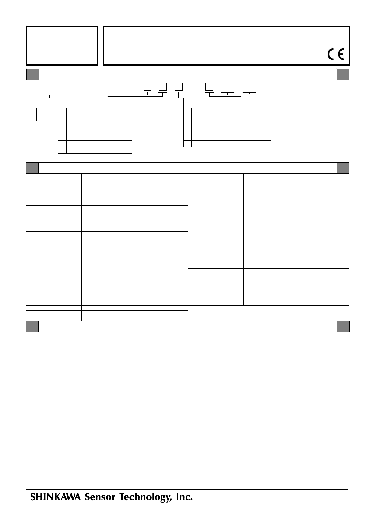
Model Code / Additional Spec. Code ( )
No entry if additional
spec. code is not specified.
FK-143F
6H14-052 Rev.6
Issued : Feb. 2015
Revised : Apr. 2019
FK-143F TRANSDUCER
Pa
e 1 of 2
FK SERIES
TRANSDUCER
SPECIFICATIONS
/ EX / SYS / GEO
-
SPECIFICATIONS
NOTICE
System
cable length Mounting plate Terminal block Intrinsically safe System calibration Geothermal spec.
1 5m 1 DIN Rail(35mm) Mount 1 Screw type
4
CSA C/US
2 9m 2 Screw mount terminal block (M4) Class , Division 1, Groups A,B,C and D
(50.8×50.8mm) 2 Spring lock terminal Ex ia C T4 , AEx ia C T4
3 Screw mount 5 ATEX (Ex ia C T4 Ga)
(92×31mm: For VK replacement)BTS(ExiaC T4 Ga)
4 Screw mount Multi-pitch C TR-CU (Ex ia C T4 Ga X)
(50.8×50.8mm and 92×31mm)


