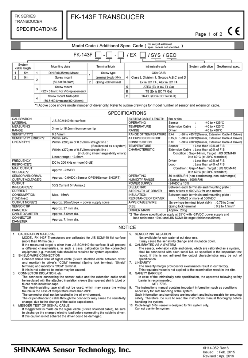
Shinkawa FK-152R User manual

MANUAL No. 6G17-037 Rev.7
Published in Jun. 2017
Revised in Dec. 2022
INSTRUCTION MANUAL
FK SERIES TRANSDUCER
Model FK-152R TRANSDUCER
Carefully read and understand this manual before using the product.
After reading this manual, store it in a safe location so that it can be
referenced readily as required.

-
-
F
FK
K-
-1
15
52
2R
R
T
Tr
ra
an
ns
sd
du
uc
ce
er
r
I
In
ns
st
tr
ru
uc
ct
ti
io
on
n
M
Ma
an
nu
ua
al
l
-
-
Thank you for purchasing the FK series FK-152R transducer.
This instruction manual (referred to as “this manual” hereafter) explains handling instructions and
cautions regarding the FK series FK-152R transducer (referred to as “this unit” hereafter).

Important notice
-
-
F
FK
K-
-1
15
52
2R
R
T
Tr
ra
an
ns
sd
du
uc
ce
er
r
I
In
ns
st
tr
ru
uc
ct
ti
io
on
n
M
Ma
an
nu
ua
al
l
-
-
1
▊Important Information ▊
Carefully read and understand this manual before using the unit. Store this manual in a safe
location so that it can be referenced readily as required.
If you have any questions regarding this manual or the unit, contact your dealer.
When using this product, it is necessary to be knowledgeable about not only the contents of this
manual, but also regarding the instrumentation and equipment connected to this unit. For safety,
it is necessary to have standard knowledge regarding safety in addition to the contents
described in this manual.
The FK series uses a variety of noise tests to evaluate EMC(electro-magnetic compatibility).
However, since the following environmental conditions will cause fluctuations in EMC
characteristics, it is important to ensure the stability of the system according to the cautionary
instructions found in this manual.
-Volume of noise produced
-Temperature and humidity
-Equipment layout
When combining this unit with other instrumentation or equipment and then selling or
transferring ownership as an assembly, always make sure to attach this manual as well and
provide it to the end user.
When disposing of this product, make sure to follow all local laws and regulations.
This unit is comprised of the following devices.
-FL-152R sensor (referred to as FL sensor hereafter)
-FW-152R extension cable (referred to as FW extension cable hereafter)
-FK-152R driver (referred to as FK driver hereafter)
During use, it is necessary to build the system structure according to the instructions in this
manual. For system structure examples, refer to page 18.
This manual contains some explanations for parts of other separately sold equipment, in order
to explain their attachment to this unit.
The illustrations of parts that are sold separately in this manual may differ from their actual
appearance.
Any company names and product names listed in this manual are the trademarks or registered
trademarks of their respective companies.
SHINKAWA Sensor Technology, Inc. owns the copyright to this manual. Unauthorized
publication of this content, and any and all copying/duplication of the content are prohibited.

Important notice
-
-
F
FK
K-
-1
15
52
2R
R
T
Tr
ra
an
ns
sd
du
uc
ce
er
r
I
In
ns
st
tr
ru
uc
ct
ti
io
on
n
M
Ma
an
nu
ua
al
l
-
-
2
▊Exclusion from liability ▊
SHINKAWA Sensor Technology, Inc. shall not be liable for any damages or injuries arising from
not following the instructions indicated in this manual, or from carelessness or neglect while
handling this unit or during its installation.
Compensation shall not be made for any damage, injury, or loss that occurs as a direct or
indirect result of the incorrect use, improper use, modification, or disassembly of this product.
SHINKAWA Sensor Technology, Inc. will not take any responsibility for any items not listed in
this document and in the warranty, including the guarantee of product merchantability,
guarantee for specific objectives or specifications, or for violation of patents, whether they are
expressed or implied.
The warranty for this unit is at the end of this manual. If a breakdown occurs in the unit, repairs
will be performed according to this warranty.
SHINKAWA Sensor Technology, Inc. will not take any responsibility for any and all results from
using parts other than those recommended by our company.
▊Confirmation of the unit and package items ▊
SHINKAWA Sensor Technology, Inc. performs strict quality control and quality inspections to
provide reliable products. When the unit first arrives, please check that it is the correct ordered
product, that there was no damage to it during its transportation, and that all accessories (ordered
items) are provided in the package.
If there is damage to the unit or missing accessories (ordered items), contact your dealer
immediately.

Index
-
-
F
FK
K-
-1
15
52
2R
R
T
Tr
ra
an
ns
sd
du
uc
ce
er
r
I
In
ns
st
tr
ru
uc
ct
ti
io
on
n
M
Ma
an
nu
ua
al
l
-
-
3
▊Index ▊
Page
Important notice ................................................................................................................1
Exclusion from liability ......................................................................................................2
Confirmation of the unit and package items ......................................................................2
Chapter 1 Safety Information.........................................................................................................5
1.1 Warning Symbols.......................................................................................................5
1.2 Cautions when handling.............................................................................................5
Chapter 2 Introduction...................................................................................................................7
2.1 Objectives of this unit.................................................................................................7
2.2 Measurement principles.............................................................................................7
2.3 Specifications.............................................................................................................8
2.3.1 Specifications of this unit..............................................................................8
2.3.2 FL sensor specifications...............................................................................9
2.3.3 FW extension cable specifications.............................................................10
2.3.4 FK driver specifications..............................................................................10
2.3.5 Additional Specification code.....................................................................10
2.3.6 Recommended specifications for the monitor cable..................................11
2.4 Outer dimensions and part nomenclature ...............................................................12
2.4.1 FL sensor outer dimensions and part nomenclature.................................12
2.4.2 FW extension cable outer dimensions and part nomenclature.................13
2.4.3 FK driver (Spring lock terminal) outer dimensions and
part nomenclature......................................................................................14
2.4.4 FK driver (Screw type terminal block (M4)) outer dimensions and part
nomenclature..............................................................................................16
2.5 System configuration example.................................................................................18
Chapter 3 Installation...................................................................................................................19
3.1 Installation environment...........................................................................................20
3.1.1 FK driver installation environment..............................................................20
3.1.2 FL sensor installation environment............................................................21
3.2 FK driver installation ................................................................................................23
3.2.1 Installation of FK-152R□-2-□, FK-152R□-3-□, and FK-152R□-4-□...23
3.2.2 Installation of FK-152R□-1-□...................................................................24
3.3 FL sensor installation...............................................................................................25
3.3.1 When using the VZ-3A bracket (separately sold)......................................25
3.3.2 When using the VZ-10A sensor sleeve (separately sold)..........................26
3.3.3 Gap adjustment..........................................................................................27
3.4 Wiring connections...................................................................................................28
3.4.1 FW extension cable connection (When using the FW extension cable)...29
3.4.2 FL sensor connection.................................................................................30
3.4.3 FK driver (Spring lock terminal) and Monitor (VM monitor) connection....30

Index
-
-
F
FK
K-
-1
15
52
2R
R
T
Tr
ra
an
ns
sd
du
uc
ce
er
r
I
In
ns
st
tr
ru
uc
ct
ti
io
on
n
M
Ma
an
nu
ua
al
l
-
-
4
3.4.4 FK driver (Screw type terminal block (M4)) and Monitor (VM monitor)
connection..................................................................................................32
3.4.5 Confirmation after completing connection.................................................34
3.4.6 Set gap voltage confirmation .....................................................................34
Chapter 4 Maintenance/Inspection...................................................................................36
4.1 Periodic inspection...................................................................................................36
4.2 Unit life.....................................................................................................................36
4.3 Troubleshooting .......................................................................................................37
Chapter 5 Individual characteristics data..........................................................................38
5.1 Standard static characteristics.................................................................................38
5.2 Sensor temperature characteristics.........................................................................39
5.3 Driver temperature characteristics...........................................................................40
5.4 Static characteristic effect by target material...........................................................41
5.5 Frequency characteristics........................................................................................42
Chapter 6 Information about intrinsically safe application.................................................43
6.1 Japan:DEKRA .......................................................................................................43
6.2 Canada / North America:CSA ...............................................................................45
6.3 Europe:ATEX, Oceania : IECEx............................................................................48
6.4 China:Ex-CCC.......................................................................................................50
6.5 Taiwan:TS..............................................................................................................54
6.6 Russia:TR-CU .......................................................................................................59
Appendix Cable wiring/laying...................................................................................................60

Chapter 1 Safety Information
-
-
F
FK
K-
-1
15
52
2R
R
T
Tr
ra
an
ns
sd
du
uc
ce
er
r
I
In
ns
st
tr
ru
uc
ct
ti
io
on
n
M
Ma
an
nu
ua
al
l
-
-
5
Chapter 1 Safety Information
Read this section carefully to use this product safely.
1.1 Warning Symbols
In this document, rules that must be followed in order to prevent injuries or financial losses to
customers, and for the safe usage of this unit, is labeled with the following markings. Make sure
to understand the contents of these cautions and make sure to follow their instructions.
Warning Symbol Meaning
This symbol is used to warn against the possibility of serious or fatal
injury.
Always follow the instructions to ensure safety.
This symbol is used to caution against the possibility of injury.
Always follow the instructions to ensure safety.
This symbol is used to draw attention to the possibility of property
damage.
Always follow the instructions to prevent damage to equipment.
Point The Point is used to emphasize important items or to provide useful
information.
1.2 Cautions when handling
Be sure to observe the following instructions for safe use of this unit.
▊Prohibited actions ▊
Never disassemble or modify this unit. And do not use the unit under conditions outside the
standards specified in the specifications.
Doing so may lead to failures of the unit, fires, or personal injuries.
Do not use transceivers and other radio equipment/cellular phones near this unit. If this unit or
signal cables are exposed to electromagnetic waves, the unit may not satisfy the precision
indicated in the specifications.

Chapter 1 Safety Information
-
-
F
FK
K-
-1
15
52
2R
R
T
Tr
ra
an
ns
sd
du
uc
ce
er
r
I
In
ns
st
tr
ru
uc
ct
ti
io
on
n
M
Ma
an
nu
ua
al
l
-
-
6
▊ Rules to follow ▊
WARNING
When installing this unit, be sure to follow the procedures described in “Chapter 3 Installation”.
If the procedures indicated are not followed, it may lead to failures of the unit, fires, or
personal injuries.
ATTENTION
Do not give the sensor tip to excessive shock or vibration. The sensor tip will be damaged.
Before operating this unit, be sure to read the instruction manuals for instruments and
equipment that will be connected to this unit.
The person handling this unit must have specialized knowledge regarding instrumentation
and other devices related to this unit.
Before touching this unit, be sure to touch a metal section near by to discharge any static
electricity.
The device may be damaged if exposed to static electricity from a person’s body.
Do not perform insulation resistance measurements or voltage endurance tests at
locations other than those with the insulation resistance and voltage endurance
specifications indicated. Doing so may damage the unit.
When performing a megger test (insulation test) of the signal transmission cable, always
disconnect the cable from the unit and the monitor.
When reconnecting the cable after a megger test, short the cable to ground first before
connecting the cable to discharge any electric charge.
Connecting cables in a charged condition to the unit or the monitor may damage the unit.
Perform the following measures to ensure the stability of the system.
- Be sure to install surge killers for each relay used near this system, devices related to
this system or signal cables connecting the system and these devices.
- Install an interlock functions on the system to prevent malfunction in the event of
trouble with the product.
- The FK driver should be put into the EMC shield enclosure, if the FK driver is installed
at noisy environment. And the enclosure should be grounded for EMC shield
grounding.
- The signal cable, FL sensor cable and FW extension cable should be lay into the metal
conduit, if the cable passes through noisy environment. And the conduit should be
grounded for EMC shield grounding.
If any one of the following conditions occurs, stop using the unit and contact your retailer.
Continuing the usage in an abnormal condition may result in fires or failures.
- When there is a strange odor coming from the unit.
- When the unit is heating up abnormally.
- If the unit is dropped
- If the casing of the unit is damaged
Store this unit in a location away from direct sunlight, under the following conditions. Do
not store in a location exposed to high temperatures and/or humidity, or where corrosive
gasses are present.
- Temperature: -40 to 80 °C
- Humidity: 30 to 95%RH (No condensation)

Chapter 2 Introduction
-
-
F
FK
K-
-1
15
52
2R
R
T
Tr
ra
an
ns
sd
du
uc
ce
er
r
I
In
ns
st
tr
ru
uc
ct
ti
io
on
n
M
Ma
an
nu
ua
al
l
-
-
7
Chapter 2 Introduction
2.1 Objectives of this unit
This unit performs non-contact measurement of the distance (gap) between the FL sensor and
the measured object (target), and outputs a voltage signal corresponding to the gap.
By combining this unit with our monitor, it is possible to measure the vibration of a rotating shaft,
its eccentricity, rotating speed etc. The unit is utilized for continuous measurement or monitoring
of shafts rotating at high speeds, in turbines, generators, compressors, etc.
This unit is not designed for use in any other applications.
2.2 Measurement principles
The gap between the FL sensor and the target is found according to the following principles.
•If an approximately 1MHz high frequency current is supplied from the oscillator in this unit to
the FL sensor, a high frequency magnetic field is created at the FL sensor.
•By the interlinkage of high frequency magnetic flux in the target, an eddy current will flow on
the target surface.
•When the eddy current flows on the target surface, a magnetic field is created at the target
side, and the sensor impedance will change.
•The output of the oscillator (voltage amplitude) changes by the change in the sensor
impedance.
•The output of the oscillator is detected, and the distance vs. output voltage is made linear by
a linearizer electrically, and the result is output.
Therefore, if the following relationships are identified in advance, it is possible to find the gap
between the FL sensor and the target by measuring the sensor impedance:
•Relationship between the FL sensor and the target gap
•Relationship of the sensor impedance
Block diagram
Linearizer

Chapter 2 Introduction
-
-
F
FK
K-
-1
15
52
2R
R
T
Tr
ra
an
ns
sd
du
uc
ce
er
r
I
In
ns
st
tr
ru
uc
ct
ti
io
on
n
M
Ma
an
nu
ua
al
l
-
-
8
2.3 Specifications
2.3.1 Specifications of this unit
6H17-042 Rev.6
Dimension of
Target
[recommended]
(mm)
A ≥6
B ≥7
C ≥2.5
D ≥16
Set gap
[recommended]
(mm)
1.0 to 1.5
D
A
B
C
D
D
A
C
B
C
• Dimension of target [recommended for rotational speed measurement]
Driver
System Cable Length :
FK-152R1 : 15m
FK-152R2 : 20m
Connector
Sensor
Extension Cable
CALIBRATION MATERIAL
JIS SCM440 flat surface
TEMPERATURE
Sensor : Less than ±6% of F.S.
MEASURING RANGE
0.25mm to 1.75mm from sensor tip
CHARACTERISTIC
Extension Cable : Less than ±4% of F.S.
SENSITIVITY*2
7.87V/mm
Condition : Gap=1.5mm, Target : JIS SCM440
SENSITIVITY ERROR*2
Within ±5%
0 to 80°C (at 20°C standard)
SCALE FACTOR ERROR*2
Within ±5% of 7.87V/mm (if calibrated as a system)
Driver : Less than ±5% of F.S.
Within ±10% of 7.87V/mm
Loop : Less than ±7% of F.S.
(including interchangeability errors)
Condition : Gap=1.5mm, Target : JIS SCM440
Step : 0.25mm, Linear range : 1.5mm
0 to 60°C (at 20°C standard)
LINEARITY*2
Within ±25
µ
m of 7.87V/mm straight line :
OPERATING
30 to 95% RH (non-condensing, non-submerged)
(if calibrated as a system)
HUMIDITY RANGE
(Sensor body : 100%RH)
Within ±45
µ
m of 7.87V/mm straight line :
POWER SUPPLY
-24VDC ± 10%
(including interchangeability errors)
DIELECTRIC
Between each terminals and mounting plate :
Linear range : 1.5mm
STRENGTH OF DRIVER
1mA or less at 500VAC for one minute
FREQUENCY RESPONCE*2
DC to 7kHz or more (-3dB)
INSULATION
Between each terminals and mounting plate :
MAX. OUTPUT VOLTAGE*2
Approx. -23VDC
RESISTANCE OF DRIVER
100MΩ or more at 500VDC
SENSOR ABNORMAL
Approx. -0.6VDC (Sensor OPEN/Sensor SHORT)
APPLICABLE WIRE SIZE
Screw type terminal block (M4) : 0.75 to 2mm2
OUTPUT VOLTAGE*2
Spring lock terminal : 0.2 to 1.5mm2
OUTPUT IMPEDANCE*2
50Ω Current 5mA (max.)
DRIVER MASS
Approx. 200g
CURRENT CONSUMPTION
Max. -15mA
Other
(10kΩ load)
OUTPUT NOISE*2
Approx. 15mVpk-pk + power supply noise
SENSOR TIP DIAMETER
Approx. 8mm dia.
CABLE DIAMETER
Approx. 3.6mm dia.
CONNECTOR DIAMETER
Approx. 7.1mm dia.
SYSTEM CABLE LENGTH
15m or 20m
OPERATING
Sensor : -40 to +177°C
TEMPERATURE RANGE
Extension Cable : -40 to +177°C
Driver : -40 to +80°C
RANGE OF TEMPERATURE
E10 : -40 to +80°C(Sensor, Extension Cable & Driver)
AT EXPLOSION PROOF
E40 : -40 to +80°C(Sensor, Extension Cable & Driver)
CONSTRUCTION
E50 : -40 to +80°C(Sensor, Extension Cable & Driver)
E70 : -40 to +80°C(Sensor, Extension Cable & Driver)
EB0 : -40 to +80°C(Sensor, Extension Cable & Driver)
EC0 : -40 to +80°C(Sensor, Extension Cable & Driver)
*2 The above specification apply at 25°C with -24VDC power supply and
load resistance 10kΩand JIS SCM440 target (thickness≥5mm).
ED0 : -40 to +80°C(Sensor, Extension Cable & Driver)
1. CALIBRATION MATERIAL
MODEL FK-152R Transducers are calibrated for JIS SCM440 flat surface
(more than 15mm dia.).
If the measured target is other than JIS SCM440 flat surface, it will present a
different characteristics. In such a case, calibration by the connected equipment
(e.g. monitor) side should be required for system operation.
2. SHIELD WIRE CONNECTION
Connect shield wire of signal cable (3-wire shielded cable between driver and
monitor) to driver’s “COM” terminal (Spring lock terminal: “Shield” terminal) and
monitor’s “COM” terminal.
If this is not adhered to, noise may be caused.
3. CONNECTOR ISOLATION, etc.
The connector connecting the sensor cable and the extension cable shall be
insulated with the attached insulation sleeve (transparent shrink tube) or fluoro
resin insulation tape.
The vinyl-insulating tape shall not be used, which may cause the wiring trouble in
the case of temperature more than 80°C.
The connector shall not be located in the oil environment.
The oil penetration to cable through the connector may cause the sensitivity
change, due to the change of the cable capacitance.
4. MEGGER TEST OF SIGNAL CABLE
If megger test is made on the signal cable (3-wire shielded cable), be
sure to discharge the charged electric load before connecting the cable to driver.If
this caution is not adhered the driver could be dameged.
5. SENSOR INSTALLATION
Not available for rain water at out door use.
It may cause the sensitivity change and insulation down.
6. CALIBRATED AS A SYSTEM
The sensor, extension cable and driver, which are calibrated as a system, shall
be connected with each serial No. as specified in the inspection test report. If this
is not adhered the output characteristics may be out of specification.
7. SCALE FACTOR ERROR and LINEARITY
The scale factor error margin and linearity margin provides for examination result
in our factory.
This regulated value is not applied to the examination result in the site.
8. SAFETY BARRIER
In case of the intrinsically safe specification, the approved following safety barrier
is recommended.
• MTL 7796-
Please use in combination with the barrier which has explosion-proof certification
in the country of use.
Linear range reduces when intrinsic safety system with barrier.(to approx. 95%)
9. The instructions manual contains important information such as conditions
necessary for safe handling of the system.
Such information and conditions are important and indispensable for ensuring
safety. Therefore, be sure to read the instructions manual thoroughly before
handling the system.
10. In the intrinsically safe system, the product cannot be used in combination
with a sensor/extension cable/driver with the intrinsically safe code "/EX□".
SPECIFICATIONS
NOTICE

Chapter 2 Introduction
-
-
F
FK
K-
-1
15
52
2R
R
T
Tr
ra
an
ns
sd
du
uc
ce
er
r
I
In
ns
st
tr
ru
uc
ct
ti
io
on
n
M
Ma
an
nu
ua
al
l
-
-
9
2.3.2 FL sensor specifications
FL-152R08
Thread size Unthreaded length Case length
M2 M10 ×1
10mm STEP, 0 - 230mm
L1 ≤L2 - 20mm
e.g.) 06 = 60mm
10mm STEP,
20 - 250mm
e.g.) 25 = 250mm
U2 3/8-24UNF
0.1inch STEP, 0 - 9.2inches
L1 ≤L2 - 0.7inches
e.g.) 04 = 0.4inches
0.1inch STEP,
0.8 -9.9inches
e.g.) 35 = 3.5inches
Specified in mm for M threaded sensor.
Specified in inch for UNF threaded sensor.
FL-152R08R
Thread size Unthreaded length Case length
M2 M10 ×1
R5 = 5mm
03 = 30mm
U2 3/8-24UNF
02 = 0.2inches
12 = 1.2inches
Specified in mm for M threaded sensor.
Specified in inch for UNF threaded sensor.
Cable allowable
bending radius
Without armor : 30mm
With armor : 50mm
With fluoro resin coating armor : 75mm
Cable allowable
tension
98.1N (10kgf)
Armor
L
Without armor
A
With armor
(Without fluoro
resin coating)
T
With armor
(With fluoro resin
coating)
Cable length
005
0.5m
010
1.0m
150
15.0m
200
20.0m
FL-152R08
-
L1
-
L2
-
L3
-
Cable length
005
0.5m
010
1.0m
150
15.0m
200
20.0m
FL-152R08R
-
L1
-
L2
-
L3
-

Chapter 2 Introduction
-
-
F
FK
K-
-1
15
52
2R
R
T
Tr
ra
an
ns
sd
du
uc
ce
er
r
I
In
ns
st
tr
ru
uc
ct
ti
io
on
n
M
Ma
an
nu
ua
al
l
-
-
10
2.3.3 FW extension cable specifications
Armor
L
Without armor
A
With armor
(Without fluoro resin coating)
T
With armor
(With fluoro resin coating)
Cable allowable
bending radius
Without armor : 30mm
With armor : 50mm
With fluoro resin coating armor : 75mm
Cable allowable
tension
98.1N (10kgf)
2.3.4 FK driver specifications
System cable length
Mounting plate
Terminal block
1
15m
1
DIN rail (35mm) mount
1
Screw type terminal block (M4)
2
20m
2
Screw mount (50.8 ×50.8mm)
2
Spring lock terminal
3
Screw mount (92 ×31mm:
for VK replacement)
4
Screw mount multi-pitch
(50.8
×
50.8mm and 92
×
31mm)
▊Terminal Arrangement ▊
2.3.5 Additional Specification code
Intrinsically safe
System Calibration
Geothermal Spec.
10 Japan : DEKRA 70 China : Ex-CCC
Ex ia
ΙΙ
C T4 Ga
Ex ia
ΙΙ
C T4 Ga
40
Canada / NorthAmerica : CSA C/US
B0
Taiwan
:
TS
Class
Ι
, Division 1, Groups A,B,C,D T4
Ex ia
ΙΙ
C T4 Ga
Ex ia
ΙΙ
C T4 Ga
C0
Russia
:
TR-CU
Class
Ι
, Zone 0, AEx ia
ΙΙ
C T4 Ga
0 Ex ia
ΙΙ
C T4 Ga X
50
Europe : ATEX
D0
Oceania
:
IECEx
Ex ia
ΙΙ
C T4 Ga
Ex ia
ΙΙ
C T4 Ga
Terminal No.
Signal
1
OUTPUT
2
COM
3
-24V
4
Shield (COM)
Terminal No.
Signal
1
OUTPUT
2
COM
・
Shield
3
-24V
Case of Screw type terminal block (M4)
Case of Spring lock terminal
Cable length
140
14.0m
145
14.5m
190
19.0m
195 19.5m
FW-152R
-
L
FK-152R
-
-
/ E
/ SYS / GEO

Chapter 2 Introduction
-
-
F
FK
K-
-1
15
52
2R
R
T
Tr
ra
an
ns
sd
du
uc
ce
er
r
I
In
ns
st
tr
ru
uc
ct
ti
io
on
n
M
Ma
an
nu
ua
al
l
-
-
11
2.3.6 Recommended specifications for the monitor cable
Use a commercially sold cable to connect the unit and the monitor.
A CVVS 3 core shielded cable (straight) is recommended, but if it is not available, a 3 line
multiple core cable for light electrical instruments (individually shielded) can be used.
Use cables of sizes are following
Terminal block
Cable conductor size
Screw type terminal block (M4)
AWG. No.18
~
14 (0.75mm
2~
2.00mm
2
)
Spring lock terminal
AWG. No.20
~
16 (0.5mm
2~
1.25mm
2
)
Cable name
Note
CVVS 3 core shielded cable (straight)
The CVVS 3 core shielded cable is also recommended in the
API STANDARD 670.
Recommendation: Copper tape shield (core wire; soft copper
wire)
(Normally, silver plated braid)
Use conduit pipe (cable rack) for wiring.
3 line multiple core cable for light
electrical instruments (individually
shielded)
Recommendation: Outer shield is aluminum tape, copper tape
shield
The multipair cable can contain a mixture of vibration signals
and displacement signals. However, vibration signals for a high
amplitude vibration can affect other vibration
signals and
displacement signals negatively, and these need to be wired on
a separate cable.
•The FK driver and FW extension cable should be installed as follows to protect from
electromagnetic influence.

Chapter 2 Introduction
-
-
F
FK
K-
-1
15
52
2R
R
T
Tr
ra
an
ns
sd
du
uc
ce
er
r
I
In
ns
st
tr
ru
uc
ct
ti
io
on
n
M
Ma
an
nu
ua
al
l
-
-
12
2.4 Outer dimensions and part nomenclature
2.4.1 FL sensor outer dimensions and part nomenclature
L1: Unthreaded length L2: Case length L3: Cable length
*1 TAG No. (TAG No. is indicated on product, if required)
*2 MODEL No. and SERIAL No.
■
FL-152R08L
■
FL-152R08A
■
FL-152R08T
*
1
*
2
*
2
*
1
*
2
*
1

Chapter 2 Introduction
-
-
F
FK
K-
-1
15
52
2R
R
T
Tr
ra
an
ns
sd
du
uc
ce
er
r
I
In
ns
st
tr
ru
uc
ct
ti
io
on
n
M
Ma
an
nu
ua
al
l
-
-
13
L1: Unthreaded length L2: Case length L3: Cable length
2.4.2 FW extension cable outer dimensions and part nomenclature
L: Cable length
*1 TAG No. (TAG No. is indicated on product, if required)
*2 MODEL No. and SERIAL No.
*
2
*
1
L2
L1
*
2
*
1
*
1
*
2
*
1
*
1
*
1
*
2
*
1
■
FW-152RL
■
FW-152RA
■
FW-152RT
■
FL-152R08R

Chapter 2 Introduction
-
-
F
FK
K-
-1
15
52
2R
R
T
Tr
ra
an
ns
sd
du
uc
ce
er
r
I
In
ns
st
tr
ru
uc
ct
ti
io
on
n
M
Ma
an
nu
ua
al
l
-
-
14
2.4.3 FK driver (Spring lock terminal) outer dimensions and part nomenclature
■FK-152R□-1-2
Unit :mm
■FK-152R□-2-2
Unit :mm
Mounting
plate
Mounting
plate

Chapter 2 Introduction
-
-
F
FK
K-
-1
15
52
2R
R
T
Tr
ra
an
ns
sd
du
uc
ce
er
r
I
In
ns
st
tr
ru
uc
ct
ti
io
on
n
M
Ma
an
nu
ua
al
l
-
-
15
■FK-152R□-3-2
Unit :mm
■FK-152R□-4-2
Unit :mm
Mounting
plate
Mounting
plate

Chapter 2 Introduction
-
-
F
FK
K-
-1
15
52
2R
R
T
Tr
ra
an
ns
sd
du
uc
ce
er
r
I
In
ns
st
tr
ru
uc
ct
ti
io
on
n
M
Ma
an
nu
ua
al
l
-
-
16
2.4.4 FK driver (Screw type terminal block (M4)) outer dimensions and part nomenclature
■ FK-152R□-1-1
Unit : mm
■ FK-152R□-2-1
Unit : mm
Shipments before 2021

Chapter 2 Introduction
-
-
F
FK
K-
-1
15
52
2R
R
T
Tr
ra
an
ns
sd
du
uc
ce
er
r
I
In
ns
st
tr
ru
uc
ct
ti
io
on
n
M
Ma
an
nu
ua
al
l
-
-
17
■ FK-152R□-3-1
Unit : mm
■ FK-152R□-4-1
Unit : mm
Shipments before 2021

Chapter 2 Introduction
-
-
F
FK
K-
-1
15
52
2R
R
T
Tr
ra
an
ns
sd
du
uc
ce
er
r
I
In
ns
st
tr
ru
uc
ct
ti
io
on
n
M
Ma
an
nu
ua
al
l
-
-
18
2.5 System configuration example
This unit is designed to fulfill the specifications when used under the following configuration.
Point Always combine the components of this unit (FL sensor, FW extension
cable, and FK driver) so that it will be configured as follows. If this unit is
not configured as shown below, or if the FW extension cable is not used in
combining the FL sensor and FK driver, the output characteristics will differ
dramatically.
FL-152R sensor FW-152R extension cable System cable length FK-152R driver
0.5m + 14.5m = 15m →FK-152R1
1.0m + 14.0m = 15m →FK-152R1
15.0m ---- = 15m →FK-152R1
0.5m + 19.5m = 20m →FK-152R2
1.0m + 19.0m = 20m →FK-152R2
20.0m ---- = 20m →FK-152R2
Point The sensor, extension cable and driver, which are calibrated as a system
at the manufacturer, shall be connected with each serial number as
specified in the inspection test report. If this is not adhered the output
characteristics may be out of specification.
This manual suits for next models
1
Table of contents
Other Shinkawa Transducer manuals