Shinko Electric CHC-S1245-5 Technical specifications

YQE8-J0092E
Date: March 8, 2005
Revised:
Revision: First Edition
Confirmation Signature
(Shinko Electric Co., Ltd.)
Approved Inspected Drew
(Custome
r
: )
Shinko Electric Co., Ltd.
Digital Photo Printer
CHC-S1245-5
Maintenance Specifications

YQE8-J0092E
Revision Record
Revised Date Correction
symbol
Descriptions ECN No.
3/8/2005 -First Edition

YQE8-J0092E
Contents
1.Scope....................................................................................................................................................1
2.Periodic Inspection................................................................................................................................2
2.1 Parts Required.................................................................................................................................................. 2
2.2 Tools Required ................................................................................................................................................ 2
2.3 Tool Required.................................................................................................................................................. 2
2.4 Maintenance Schedule..................................................................................................................................... 3
2.5 Inspection Contents ......................................................................................................................................... 4
2.6 Description for point of cleaning..................................................................................................................... 6
2.7 Description for point of lubrication............................................................................................................... 11
3.Adjustment ..........................................................................................................................................14
3.1 Power Unit Voltage Setting........................................................................................................................... 14
3.1.1 +5V Setting............................................................................................................................................. 14
3.1.2 Thermal Head Power (THV) Setting...................................................................................................... 15
3.1.3 +24V Verification................................................................................................................................... 15
3.2 Timing Belts Adjustment............................................................................................................................... 16
3.2.1 For Feed Roller Drive............................................................................................................................. 16
3.2.2 For Feed Roller Drive............................................................................................................................. 16
3.2.3 For Roll Paper Drive............................................................................................................................... 16
3.3 Print Density Adjustment .............................................................................................................................. 17
3.4 Resetting Maintenance Print Counter and Cutter Counter............................................................................. 18
4.Test Printing........................................................................................................................................20
5.Troubleshooting ..................................................................................................................................21
5.1 How to Use This Specification...................................................................................................................... 21
5.2 Troubleshooting Table................................................................................................................................... 22
5.2.1 Troubles during Power On and Off ........................................................................................................ 22
5.2.2 Error Messages on LCD Display when Power Is On ............................................................................. 24
5.2.3 Troubles in Operation Buttons and Indicators........................................................................................ 29
5.2.4 Troubles in Paper Feed........................................................................................................................... 31
5.2.5 Troubles in Feeding Ink Ribbon............................................................................................................. 34
5.2.6 Troubles in Printing and Contents of Printing........................................................................................ 36
5.2.7 Occurrence of Abnormal Noise.............................................................................................................. 39
5.2.8 Troubles in Connection........................................................................................................................... 41
Appendix 1: Maintenance Parts List (including Periodic Replacement Parts).........................................43
Appendix 2: BLOCK DIAGRAM................................................................................................................45

YQE8-J0092E
1
1.Scope
This document is applicable to the following Shinko Digital Photo Printer.
Applicable Model Name:CHC-S1245-5
Related Documents
・Maintenance Parts Replacement Procedures YQE8-J0093E
・Operation Manual YTE8-J0124E

YQE8-J0092E
2
2.Periodic Inspection
2.1 Parts Required
№Description Parts Number Q’ty Supplier Remarks
1 Head Cleaning Kit 060-91-7146 1Option
2 Isopropyl Alcohol (IPA) or Ethyl
Alcohol (more than 99% purity)
Some Available on
market
3 Bleached Cloth Some Available on
market
4 Grease (equivalent to MOLYKOTE
PG-671)
Some Available on
market
5Wire Tire (insulation lock) 060-64-8011 20
2.2 Tools Required
Description Model Type Q’ty
+Philips Screwdriver #0(Micro-driver)1
+Philips Screwdriver #11
+Philips Screwdriver(small)#2 (less than 100mm in length)1
+Philips Screwdriver #21
+Philips Screwdriver #2(more than 300mm in length)1
+Philips Screwdriver #2(Latch type)1
−Flat-blade Screwdriver(small)2.5×100 1
−Flat-blade Screwdriver(small)4.5×50 1
Nipper 1
Pliers 1
Scissors 1
Clip for Digital Voltmeter Refer to figure below for aspect 2
Clip for Digital Voltmeter
2.3 Tool Required
Description Remarks
Digital Voltmeter 0.1V unit of measurement

YQE8-J0092E3
2.4 Maintenance Schedule
Periodic inspection is performed according to the following schedule. If problem is detected during the inspection, adjustment or Replacement of parts may be
necessary. Schedule
○(circle) denotes to Perform, R denotes to Replace
Number of Prints
(K=1,000 prints)
№Inspect Item
10K 20K 30K 40K 50K 60K 70K 80K 90K 100K
Remarks
1 Thermal Head ○R○R○R○R○R
2 Platen Roller ○○○○○○○○○○
3 Timing Belt ○○○○○○○○○○
4 DC Power Supply ○
5DCMotorASSY
(Ribbon winding)
RRR
6DCMotorASSY
・Thermal Head Up/Down
・Pinch Roller UP/Down
・Paper Feed Pinch Up/Down
・Paper Ejection Pinch Up/Down
R
7 Ribbon Brake 2 ASSY R
8 Pinch Roller ASSY ○○○○○○○○○○
9 Cleaning ○○○○○○○○○○
Lubricate ○○○○○
10
Lubricate (DC Motor ASSY) ○○○○○○○○○○
Remarks: Replace DC Power Supply and DC fan (Control box cooling) every 30,000 hours of total printer working time.

YQE8-J0092E4
2.5 Inspection Contents
№Inspection Items Inspection Contents
1 Thermal Head Perform test printing, and replace the Thermal Head ASSY if the following
problem occurs (Refer to Section 4 of this document for test printing
procedures)
-Visible white line on output surface (ink does not transfer to the paper
even after cleaning the thermal print head.
-Using pattern with fairly even density, there is extreme uneven density the
output. (Refer to Maintenance Parts Replace Procedures for replacement
procedures)
2 Platen Roller Roll the Platen Roller to check for unevenness or scratches on the surface.
Replace the platen if problem occurs with the output. (Refer to Maintenance
Parts Replace Procedures for replacement procedures)
3 Timing Belt Inspect the timing belt tension (Refer to Section 3.2 of this document).
Turning the pulley to check for scratches and split on the timing belt.
Replace the timing belt if the problem occurs (Refer to Maintenance Parts
Replacement Procedures for replacement procedures).
4 DC Power Supply Inspect the +5V, +24V, and THV output value. (Refer to Section 3.1 of this
document for more details)
5 Pinch Roller Roll the Pinch Roller to check for unevenness or scratches on the surface.
Replace the pinch Roller if problem occurs with the output (Refer to
Maintenance Parts Replace Procedures for replacement procedures).
6 Cleaning (1) Clean the thermal head with Head Cleaning Kit (Refer to Section 2.6 for
more details).
(2) Clean the surface of rubber rollers with Isopropyl Alcohol (IPA) in
bleached cloth (Refer to Section 2.6 for more details).
①Platen
②Cleaning Roller
③Paper Feed Roller (Paper feed)
④Paper Feed Roller (Paper transport)
⑤Ejection Roller
(3) Clean the front of peeling plate and ribbon mark sensor reflector with
Isopropyl Alcohol (IPA) in bleached cloth (Refer to Section 2.6 for more
details).
(4) Clean the paper sensor and ink ribbon sensor with Head Cleaning Kit.
(5) Clean the surface of Pinch Roller with dry and bleached cloth.
(6) Vacuum and/or clean the paper dust inside the printer.
(7) Clean the covers with dry and bleached cloth (Refer to Operation Manual
for more details).
(8) Clean the fan filters at upper and side cover (Refer to Operation Manual
for more details).

YQE8-J0092E5
№Inspection Item Inspection Contents
7 Lubricate Apply some grease (Molykote PG-671) to each of the following
sections.
(1)DC Motor ASSY (Ribbon roll-up)
①Circumference of Worm Gear
(2)DC Motor (Pinch Roller)
①Circumference of Worm Gear
②Circumference of the Pinch Cam (left and right)
③Circumference of Gear
(3)DC Motor (Thermal Head)
①Circumference of Worm Gear
②Circumference of Head Cam
(4)DC Motor (Paper Feeding Pinch Roller)
①Circumference of Worm Gear
②Circumference of Feed Pinch Roller Cam
(5)DC Motor (Paper Ejection Pinch Roller)
①Circumference of Worm Gear
(6)Sub-Motor
①Circumference of Pinion Gear

YQE8-J0092E6
2.6 Description for point of cleaning
(1)Covers for remove
(2)Thermal Head Heat Element
Cleaning while opening Upper Unit
(3)Platen
Cleaning while opening Upper Unit
Platen
Thermal Head
Heat Element
Front CoverSide Cover L2 Side Cover R2
Side Cover R
Side Cover L
Upper Cover

YQE8-J0092E7
(4)Cleaning Roller(Paper Ejection side)
Remove the Cleaning Roller and clean while opening Upper Unit
(5)Cleaning Roller(Paper Feed side)
Remove the Cleaning Roller and clean while opening Upper Unit
(6)Paper Feed Roller
Clean the Paper Feed Roller while opening Paper Cover.
Cleaning Roller(Paper Ejection side)
Cleaning Roller(Paper Feed side)
Paper Feed Roller
YQE8-J0092E8
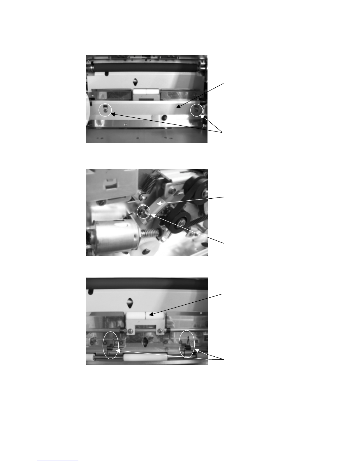
(7)Paper Feed Roller (For Paper Transport)
①Remove Cleaning Roller(Paper Feed side)
②Remove 2 screws (M3 x 6) which hold Print Position Sensor Cover, and remove Print Position Sensor
Cover.
③Remove side cover R.
④Remove a screw (M3 x 6) which holds Feed Pinch Up Lever and remove Feed Pinch Up Lever.
⑤Remove the spring (roller side) which holds Feed Pinch Roller, move the Feed Pinch Roller upwards, and
then clean the Pinch Roller.
Print Position Sensor Cover
Screw
Screw
Feed Pinch Up Lever
Feed Pinch Roller
Helical Torsion Spring

YQE8-J0092E9
(8)Cleaning Ejection Roller
①Remove Side Cover L, Side Cover R, Front Cover, and cleaning roller (ejection side).
②Remove 2 screws (M3x6) which hold PCB HSSV7-LCDSOSA-F ASSY and remove the PCB (removing
wire harness is not required).
③Remove 2 screws (M3x6) which hold the Paper Cutter Unit, then remove the Paper Cutter Unit, and clean
the Ejection Roller.
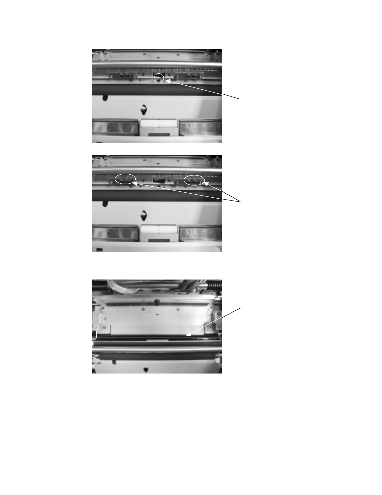
(9)Separation Plate and Ribbon Sensor Reflection Shield
Clean the Separation Plate and Ribbon Sensor Reflection Shield with the upper unit opened.
Separation PlateRibbon Sensor Reflection Shield
Warnin
g
: Do not touch the blade of the cutter unit in order to avoid in
j
ur
y
.
Screw
HSSV7-LCDSOSA-F ASSY
Paper Cutter Unit
Screw
YQE8-J0092E10
(10)Paper Edge Sensor and Ribbon Sensor
Clean the Paper Edge Sensor and Ribbon Sensor with the upper unit opened.
(11)Main Pinch Roller
Clean the Main Pinch Roller with the upper unit opened.
Main Pinch Roller
Paper Edge Sensor
Ribbon Sensor

YQE8-J0092E11
2.7 Description for point of lubrication
(1)Lubricating driving system of DC motor for ribbon winding
Lubricate the driving system of DC motor for ribbon winding with Side Cover L removed.
(2)Lubricating driving system of DC motor for pinch roller
Lubricate the driving system of DC motor for pinch roller with Side Cover L and Side Cover R removed.
Circumference of Pinch Roller Cam Circumference of Pinch Roller Cam
Worm Gear
Worm Gear and Circumference
of Gear

YQE8-J0092E12
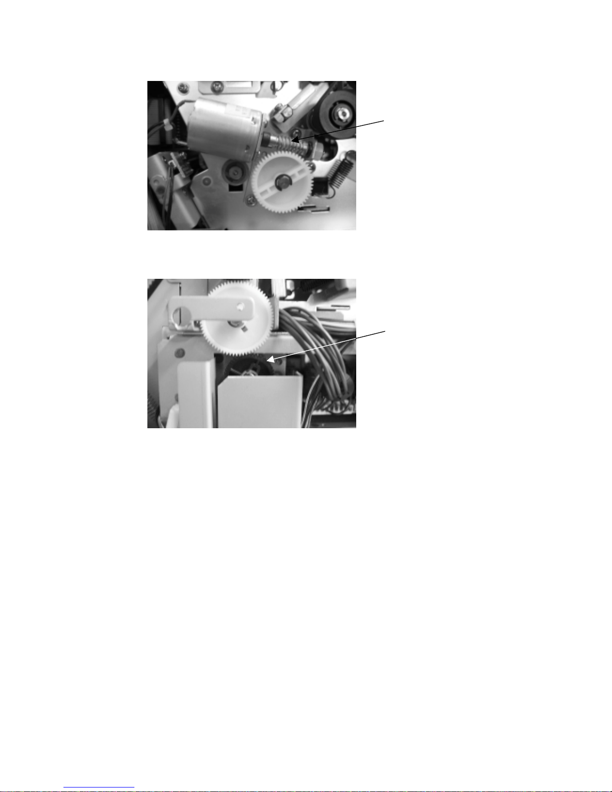
(3)Lubricating driving system of DC motor for thermal head
Lubricate the driving system of DC motor for thermal head with the Upper Cover and Head Gear Cover
removed.
Circumference of Head Cam Circumference of Head Cam
(4)Lubricating DC motor system for paper feed pinch roller
Lubricate the DC motor system for paper feed pinch roller with Side Cover L and Side Cover L2 removed.
Worm Gear
Worm Gear
YQE8-J0092E13
(5)Lubricating DC motor system for ejection pinch roller
Lubricate the DC motor system for ejection pinch roller with Side Cover R removed.
(6)Lubricating driving system of sub-motor
Lubricate the driving system of sub-motor with Side Cover L and Side Cover L2 removed.
Circumference of Pinion Gear
Worm Gear
YQE8-J0092E14
3.Adjustment
3.1 Power Unit Voltage Setting
Remove the main cover and set the power unit voltage by the following procedures.
3.1.1 +5V Setting
(1)Measurement Conditions
Turn the Power on, and measure under ready condition.
(Ink Ribbon and Paper are not required with control PC board connected)
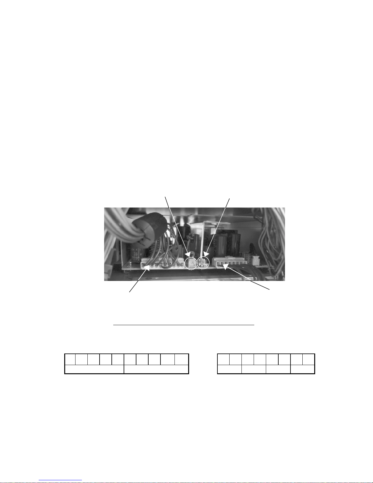
(2)Setting Voltage
Connect the digital voltmeter directly to the +5V terminal (pin 1 or 2) and 0V terminal (pin 3 or 4) of CN3
connector on DC Power Supply and verify whether Power output is under the following figure.
+5V Voltage:5.15±0.1 [V]
If it is not set correctly, set the voltage by +5V adjustment volume of which shown at the following figure.
(Turning the volume clockwise increases the voltage.)
View of DC Power Supply from the left side of the Printer
CN2 pin assignment (10 pins) CN3 pin assignment (8 pins)
12345678910 12345678
THV GND +5V 0V +24V P0V
0V, P0V, and GND are jumpered.
THV Variable Volume +5V Variable Volume
CN3
Pin 1 〜 Pin 8
CN2
Pin 1 〜 Pin 10

YQE8-J0092E15
3.1.2 Thermal Head Power (THV) Setting
(1)Measurement Conditions
Turn the Power on, and measure under ready condition.
(Ink Ribbon and Paper are not required with control PC board connected)
(2)Setting Voltage
①Open the Upper Cover, and read the THV value that is stated in the nameplate on the Thermal Head cover
(see below).
②Close the Upper Cover.
③Connect the digital voltmeter directly to the THV terminal (pin 1) and GND terminal (pin 10) of CN2
connector on DC Power Supply and set Power output under the following figure.
Set the voltage to +/- 0.1V limit to the THV value.
To set the THV value, use the THV variable volume described in Section 3.1.1.
(Turning the volume clockwise increases the voltage.)
3.1.3 +24V Verification
(1)Measurement Conditions
Be sure to perform the procedure for "+5V Setting" described in Section 3.1.1 first.
Turn the Power on, and measure under ready condition.
(Ink Ribbon and Paper are not required with control PC board connected)
(2)Setting Voltage
①Connect the digital voltmeter directly to the +24V terminal (pin 5 or 6) and P0V terminal (pin 7 or 8) of the
CN3 connector on DC Power Supply and set Power output under the following figure.
Verify whether the voltage is set at 24V +/- 1.44 V
If it is not set, replace DC Power Supply.
24.7V 4625Ω0707000001
5B04 6038 TPH216R66
THV value

YQE8-J0092E16
3.2 Timing Belts Adjustment
3.2.1 For Feed Roller Drive
①Loosen Tension Pulley Screw.
Tension pulley presses timing belt at appropriate strength by spring.
②Tighten Tension Pulley Screw.
3.2.2 For Feed Roller Drive
①Loosen Tension Pulley Screw.
Tension pulley presses timing belt at appropriate strength by spring.
②Tighten Tension Pulley Screw.
3.2.3 For Roll Paper Drive
①Loosen Tension Pulley Screw.
Tension pulley presses timing belt at appropriate strength by spring.
②Tighten Tension Pulley Screw.
Timing Belts
Tension Pulley Screw
Timing Belts
Tension Pulley Screw
Timing Belts
Tension Pulley Screw

YQE8-J0092E17
3.3 Print Density Adjustment
Print density setting is done for every Thermal Head. Therefore after replacing the thermal head, set the print
density by the following procedures.
Turn the Power On by pressing “PAPER SET” and “CLEAR/PAPER REWIND” keys at the same time.
LCD displays “Density Setup Mode” afterwards.
Press “MENU” key.
Press “ENTER” key.
Press “ENTER” key.
This shows the current setting.
By pressing “+” or “-“ keys, change this value to the density that is stated in Thermal Head (Spare
Parts). Press “CLEAR” key until “Ready” appears on LCD.
Confirm the setting value by pressing the "ENTER" key, then press the "CLEAR" key until "Ready"
appears on LCD.
Remarks:Do not change the setting other procedures than explained above. If you have entered to
other setting mode, press “CLEAR” key or turn off the power.
Initializing
DensitySetUpMode
READY:8×10
Density
Density :YMC
Density YMC ***
Table of contents
Other Shinko Electric Printer manuals


