Shinko CIT-200 User manual
PLC INTERFACE UNIT
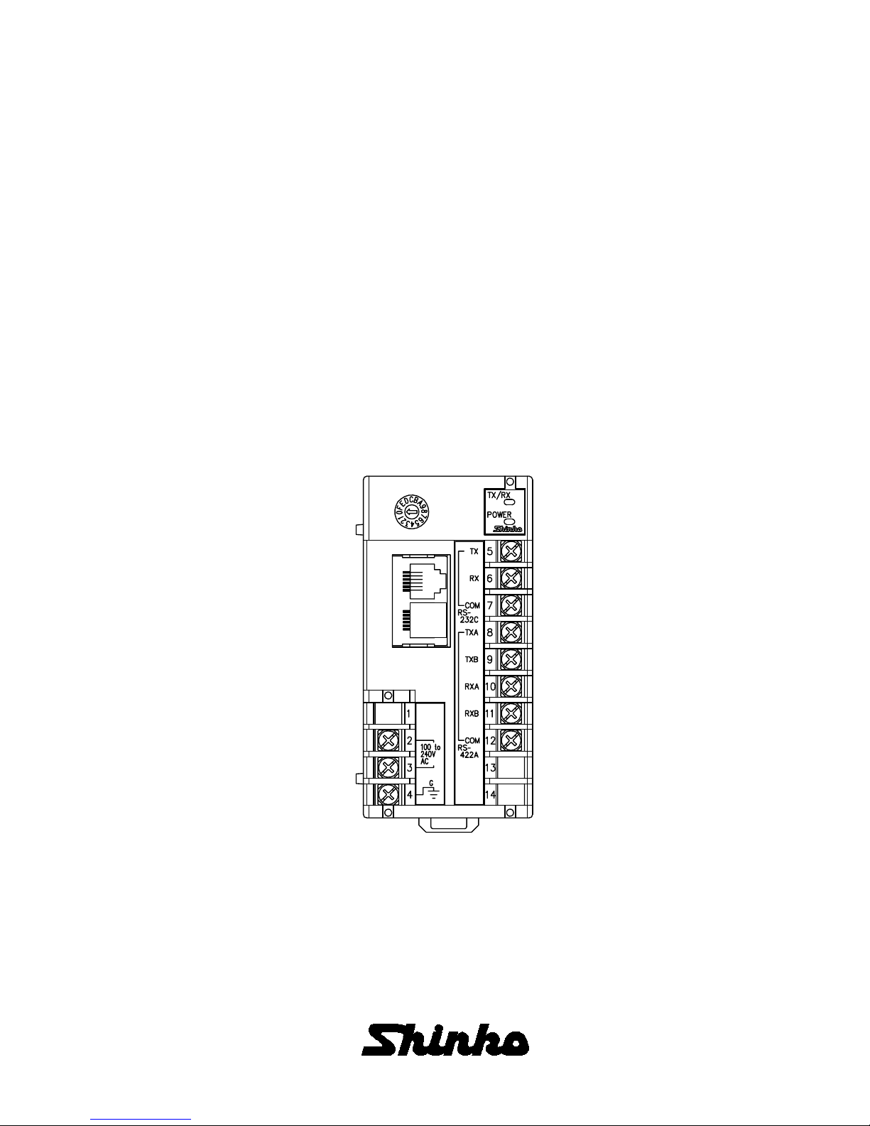
CIT-200
INSTRUCTION MANUAL

2
PREFACE
Thank you for the purchase of our PLC Interface Unit CIT-200.
This manual contains instructions for the mounting, functions, operations and notes when operating the
CIT-200.
For confirmation of the model and specifications, please read this manual carefully before starting operation.
To prevent accidents arising from the misuse of this unit, please ensure the operator using it
receives this manual.
Notes
• This instrument should be used according to the specifications described in the manual.
If it is not used according to the specifications, it may malfunction or cause fire.
• Be sure to follow the warnings, cautions and notices. If they are not followed, serious injury or malfunction
may occur.
• Do not apply a commercial power source to the sensor which is connected to the input terminal nor allow the
power source to come into contact with the sensor.
• Specifications of the CIT-200 and the contents of this instruction manual are subject to change without
notice.
• Care has been taken to assure that the contents of this instruction manual are correct, but if there are any
doubts, mistakes or questions, please inform us or the shop you purchased the unit.
• Any unauthorized transfer or copying of this document, in part or in whole, is prohibited.
• Shinko Technos Co., Ltd. is not liable for any damages or secondary damages incurred as a result of
using this manual, including any indirect damages.
Safety precautions
(Be sure to read these precautions before using our products.)
The safety precautions are classified into two categories: “Warning” and “Caution”.
Depending on circumstances, procedures indicated by Caution may be linked to serious results
and so be sure to follow the directions for usage.
Warning
Procedures which may lead to dangerous conditions and cause death or serious injury, if not
carried out properly.
Caution
Procedures which may lead to dangerous conditions and cause superficial to medium injury or
physical damage or may degrade or damage the product, if not carried out properly.

3
1. Installation precautions
Warning
Turn the power supplied to the instrument OFF before mounting.
Working or touching the terminal with the power switched ON may result in severe
injury or death due to Electric Shock.
Caution
This instrument is intended to be used under the following environmental conditions (IEC61010-1):
Overvoltage category
, Pollution degree 2
Mount the unit in a place with:
(1) A minimum of dust, and an absence of corrosive gases
(2) No flammable, explosive gases
(3) No mechanical vibrations or shocks
(4) No exposure to direct sunlight, an ambient temperature of 0 to 50 (32 to122 ) that does not
change rapidly
(5) An ambient non-condensing humidity of 35 to 85%RH
(6) No large capacity electromagnetic switches or cables through which large current is flowing
(7) No water, oil or chemicals or where the vapors of these substances can come into direct contact
with the unit
Note: Although the case of this instrument is made of flame resisting resin, do not install
this instrument near flammable material.
Avoid setting this instrument directly on flammable material.

4
2. Wiring precautions
Warning
Turn the power supplied to the instrument OFF before wiring or checking.
Working or touching the terminal with the power switched ON may result in severe
injury or death due to Electric Shock.
Caution
• Do not leave wire chips in the instrument, because they could cause fire, malfunction or trouble.
• Use the solderless terminal with an insulation sleeve that fits to the M3 screw when wiring the CIT-200.
• The terminal block of the CIT-200 is designed to be wired from the left side. The lead wire must be
inserted from the left side of the terminal, and fastened with the terminal screw.
• Tighten the terminal screw with the specified torque.
If excessive force is applied to the screw when tightening, the screw or case may be damaged.
3. Running and maintenance precautions
Warning
• Do not touch live terminals. It may cause electric shock or problems in operation.
• Turn the power supply to the instrument OFF before cleaning the module or retightening the screws.
Doing this work while the power is ON may result in severe injury or death due to electric shock.

5
CONTENTS
1. Overview
1.1 Overview of the CIT-200 ------------------------------------------------------------------------------------ 6
1.2 Units and structure when applying the CIT-200 to the C series ---------------------------------- 6
1.3 System configuration ---------------------------------------------------------------------------------------- 7
1.4 Parameter exchange ----------------------------------------------------------------------------------------- 7
2. Model name
2.1 Model name ---------------------------------------------------------------------------------------------------- 8
2.2 How to read the model name label ----------------------------------------------------------------------- 8
3. Name and functions of the sections --------------------------------------------------- 8
4. Setup ------------------------------------------------------------------------------------------------------------ 9
5. Mounting
5.1 Site selection-------------------------------------------------------------------------------------------------- 11
5.2 External dimensions ---------------------------------------------------------------------------------------- 11
5.3 DIN rail mounting and removal --------------------------------------------------------------------------- 11
6. Wiring connection
6.1 Terminal arrangement -------------------------------------------------------------------------------------- 12
6.2 Communication interface ---------------------------------------------------------------------------------- 12
6.3 Wiring connection example ------------------------------------------------------------------------------- 13
6.3.1 Wiring between the CIT-200 and Mitsubishi Calculator link unit, Serial
communication unit ---------------------------------------------------------------------------------- 14
6.3.2 Wiring between the CIT-200 and Mitsubishi Micro PLC ------------------------------------ 14
6.3.3 Wiring between the CIT-200 and Omron Host link unit ------------------------------------- 15
6.3.4 Wiring between the CIT-200 and Fuji Interface module ------------------------------------- 16
7. Communication between the CIT-200 and Mitsubishi PLC
7.1 Setup
7.1.1 Setup of Calculator link unit (AJ71UC24) ------------------------------------------------------- 17
7.1.2 Setup of Calculator link unit (A1SJ71UC24-R4) ---------------------------------------------- 18
7.1.3 Setup of Micro PLC (FX2N-XXMR) -------------------------------------------------------------- 18
7.1.4 Setup of Serial communication unit (QJ71C24) ----------------------------------------------- 19
7.2 Initial setting
7.2.1 Initial setting of Calculator link unit (AJ71UC24, A1SJ71UC24-R4) --------------------- 20
7.2.2 Initial setting of Micro PLC (FX2N-XXMR) ----------------------------------------------------- 21
7.2.3 Initial setting of Serial communication unit (QJ71C24) -------------------------------------- 22
7.3 Communication details-------------------------------------------------------------------------------------- 23
8. Communication between the CIT-200 and Omron PLC
8.1 Setup of Host link unit (C200H-LK202-V1) ----------------------------------------------------------- 34
8.2 Initial setting of Host link unit (C200H-LK202-V1) -------------------------------------------------- 34
8.3 Communication details ------------------------------------------------------------------------------------- 35
9. Communication between the CIT-200 and Fuji PLC
9.1 Setup of Interface module (NC1L-RS4) --------------------------------------------------------------- 41
9.2 Initial setting of Interface module (NC1L-RS4) ------------------------------------------------------ 42
9.3 Communication details ------------------------------------------------------------------------------------ 42
10. Specifications
10.1 Standard specifications ---------------------------------------------------------------------------------- 48
10.2 Optional specifications ----------------------------------------------------------------------------------- 49
11. Troubleshooting ------------------------------------------------------------------------------------ 50
Table of contents
Other Shinko Recording Equipment manuals


