Shinko HR-701 User manual

Hybrid recorder
HR-700
(Pen writing type)
Instruction manual
㩷
㩷
㩷
㩷
㩷
㩷
㩷
㩷
㩷
㩷
㩷
㩷
Systems & Services
PO Box 1 Ilkley West Yorkshire LS29 8EU
PO Box 1 Ilkley West Yorkshire LS29 8EU
Phone: 01943 602001 Fax: 01943 816796
Phone: 01943 602001 Fax: 01943 816796
Ltd
instrumentation
n

㵪1㵪
For safety using
Thank you for purchasing our HR-701 type (HR-702 type) Hybrid Recorder.
In order to exhibit all the functions of this instrument effectively and correctly, read and understand this
instruction manual thoroughly before using the instrument.
The symbols below are used in this instrument for the cautioning information.
Symbols used in the instrument
This shows “Caution for handling”. This symbol is used on the parts need
to refer to the instruction manual for protecting human body and the
instrument.
This shows “Protective grounding”.
Be sure to provide protective grounding prior to the operation of this
instrument.
This shows “Risk of electric shock”.This symbol is used on the parts, which
has a risk of electric shock.
Be sure to observe the following warnings/cautions and those written in this
manual in order to secure safety in handling the instrument.
WARNING
In order to prevent electric shock; be sure to disconnect this instrument
from the main power source when wiring it.
(1) In order to prevent an electric shock; be sure to provide protective
grounding prior to turning on this instrument.
(2) Do not cut a protective grounding conductor or disconnect protective
grounding.
(1) Make sure that the supply voltage for this instrument conforms to the
voltage of the supply source.
(2) Attach a protective cover prior to turning on this instrument.
Do not operate this instrument in the environment where it is exposed to
a combustible/explosive/corrosive gas or water/steam.
Provide input and output wiring after turning off the power.
General
Protective㩷Grounding
Power Source
Working Environment
Input and Output㩷㪮㫀㫉㫀㫅㪾㩷
i
i
Tel: (01943) 602001 Fax: (01943) 816796

㵪2㵪
CAUTION
Do not unused terminals for other purposes such as relaying, etc.
Do not touch the switches, etc. inside this instrument. Also, do not
replace the main unit or printed circuit boards. When this is neglected,
we cannot guarantee functioning of the instrument. Contact our dealer
where you purchased the instrument, or our sales representative.
When transporting this instrument or the equipment with this instrument
incorporated in it, take measures to prevent opening the door and falling
out the inner module.
㨇Note 㨉
(1) Deliver this instruction manual to an end user.
(2) Prior to handling this instrument, be sure to read this manual.
(3) If you have any questions on this manual or find any errors or
omissions in this manual, contact our sales representative.
(4) After reading this manual, keep it carefully near the instrument.
(5) When the manual is lost or stained, contact our sales representative.
(6) It is prohibited to copy or reproduce this manual without our
permission.
(1) When installing this instrument, put on a protective gear such as
safety shoes, helmet, etc. for your safety.
(2) Do not put your foot on the installed instrument or get on it, because it
is dangerous.
Only our servicemen or people authorized by Shinko are allowed to
remove and take the inner module, the main unit and printed circuit
boards apart.
(1) Dispose the replaced batteries in a correct way.
(2) Do not incinerate plastics of maintenance parts and replacement
parts.
㩷㩷A harmful gas may be produced.
(1) Use dry cloth to clean the surface of this instrument.
(2) Do not use any organic solvent.
(3) Clean the instrument after the power is turned off.
This instruction manual is subject to change without prior notice.
Input and Output Wiring
Transportation
Inside of Instrument
Instruction Manual
Installation
Maintenance
Disposal
Cleaning
Revisions
i
i
Tel: (01943) 602001 Fax: (01943) 816796

㵪3㵪
Using procedure for this manual
Using procedure
This instruction manual consists of “For safety using”, “Contents” and “Chapter 1 to Chapter 11” as below.
Read the corresponding sections for your purpose to use this instrument.
Chapter and TITLE For purchase
and install
For initial
setting and
change
setting
For daily
operation
For using
communication
For
maintenance
and
trouble-shootin
g
For safety using (page 1) ٧٧٧٧٧
1. INTRODUCTION ٧
2. CONSTRUCTION ٤٤٤ ٤
3. INSTALLATION ٧٤
4. WIRING ٧٤٤٤٤
5.PREPARATIONS FOR
OPERATION ٤٧
6. OPERATION ٤٧
7. DEVICE SETTING ٧٤٤
8.COMMUNICATIONS ٧
9. MAINTENANCE
٧
10.TROUBLESHOOTIG ٤٧
11. SPECIFICATIONS ٤٤
٤
䃁㩷 䋺Be absolutely certain to read this.
䂾㩷 䋺Be certain to read this if you need.
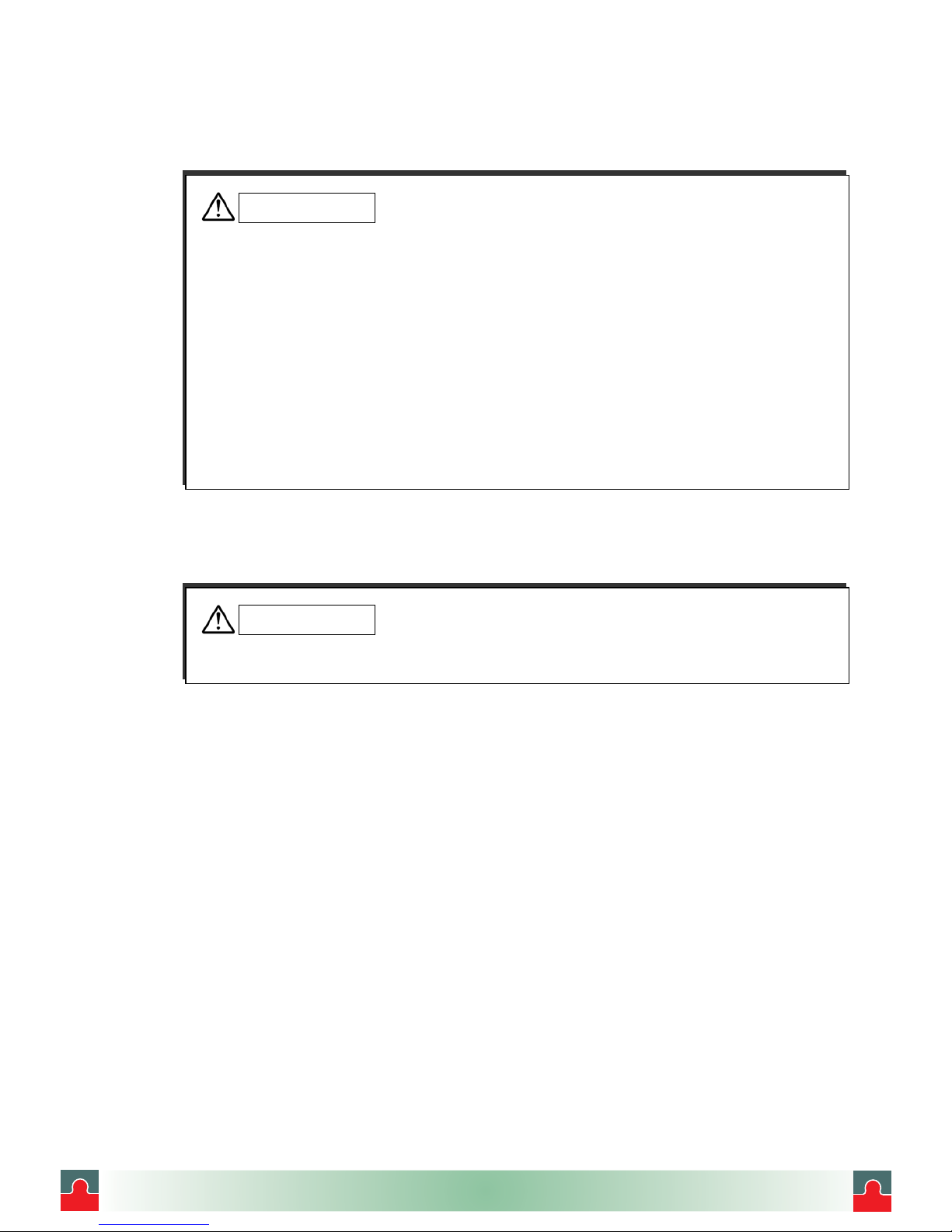
The symbols below are used on the warning and cautioning information in this manual.
Symbols used in this manual
WARNING Failure to observe this information could result in death or injury.
Be absolutely certain to read this.
CAUTION
Failure to observe this information could damage the instrument.
Be certain to read it.
㨇Note㨉This is cautionary information for correct use of the instrument.
Be certain to read it.
㨇Reference㨉This is information to help you use the functions of this instrument more
effectively.
Guide of Instruction manual
The instruction manuals of this instrument are as the table below.
Name Part No. Outline
㧝
HR-700 Hybrid Recorder
(Pen type) instruction
manual
HR72E
Explanation for installing,
wiring, standard operation.
And setting or operation for
using this instrument.
㧞
HR-700 Hybrid Recorder
Communication Command
instruction manual
HR7CE
Explanation for reading and
writing data of the recorder by
communication function.
This
manual
i
i
Tel: (01943) 602001 Fax: (01943) 816796

㵪4㵪
CONTENTS
1. INTRODUCTION..............................................................6
1.1Checking the Accessories.................................................... 6
1.2Checking the Type and Specifications ................................ 8
1.3Temporary Storage............................................................... 9
1.4Indication Card...................................................................... 9
2. CONSTRUCTION ..........................................................10
2.1Appearance ........................................................................ 10
2.2Display Screen and Operation Keys ..................................11
2.2.1Display Screen...............................................................11
2.2.2Operation Keys............................................................. 12
3. INSTALLATION..............................................................13
3.1 External Dimensions and
Panel Cutout Dimensions........................ 13
3.2Mounting to the Panel ........................................................ 14
3.2.1Procedure for Mounting to the Panel........................... 14
3.2.2Mounting to the Panel
in compliance with the IP65.................. 15
4. WIRING ..........................................................................16
4.1Terminal arrangement and Power Wiring.......................... 16
4.1.1Terminal Layout ............................................................ 16
4.1.2Power Wiring ................................................................ 16
4.1.3Wiring Procedure.......................................................... 17
4.2Input Wiring......................................................................... 18
4.2.1Wiring Procedure.......................................................... 18
4.3DI function/Alarm Output Wiring (Option).......................... 20
4.3.1DI function/Alarm Output Wiring Example................... 20
4.3.2Alarm Output Wiring Procedure................................... 21
4.3.3DI function Wiring Procedure ....................................... 21
4.4Communication Wiring....................................................... 22
4.4.1RS-232C Wiring............................................................ 22
4.4.2RS-485 Wiring .............................................................. 22
5. PREPARATIONS FOR OPERATION ...........................23
5.1Setting the Chart Paper...................................................... 23
5.2Setting the Cartridge Pen................................................... 30
5.3Setting the Ribbon Cassette .............................................. 32
6. RUNNING.......................................................................37
6.1 Running............................................................................... 37
6.1.1Status after Initial Screen ............................................. 37
6.2Recording............................................................................ 38
6.2.1Recording Colors.......................................................... 38
6.2.2Printing Color ................................................................ 38
6.2.3Pen Gap........................................................................ 38
6.2.4Gaps between Pens and Printer.................................. 38
6.2.5Print gap collection ....................................................... 39
6.3How to Record.................................................................... 39
6.3.1Starting/Stopping Recording Operation....................... 39
6.3.2Feed the Chart Paper................................................... 39
6.3.3Print Sample ................................................................. 40
6.4Digital Print.......................................................................... 41
6.4.1Manual Print.................................................................. 41
6.4.2List Print ........................................................................ 42
6.4.3Engineering List Print ................................................... 44
6.5Changing the Display ......................................................... 46
6.5.1Auto Display㧨㧪..........................................46
6.5.2Manual Display㧨㧪.........................................46
6.5.3Date Display㧨㧪..........................................46
6.5.4Time Display㧨㧪..........................................46
6.5.5Display Off㧨㧪.................................................46
7. DEVICE SETTING......................................................... 47
7.1Setting the Setup Mode ......................................................47
7.1.1Setting the Range..........................................................50
(1)Setting method...............................................................50
(2)(Current/Voltage)㧘(Thermocouple)㧘
(Resistance Temperature Detector) ...................51
(3)(Scaling) ......................................................53
(4)(Square Root) .................................................55
(5)(Decade)......................................................57
(6)(Difference)㧘(Sum)㧘
(Average)......................59
(7)(Skip) ...............................................................60
7.1.2Setting the Alarm...........................................................61
7.1.3Setting the Unit ..............................................................63
(1)Character Code Table ...................................................64
7.1.4Setting the Chart Speed................................................65
7.1.5Setting the Date and Time ............................................66
7.1.6Copying the Setting Data ..............................................67
7.1.7Setting the Other Functions ..........................................68
(1)(Zone Recording)............................................69
(2)㧔Partial Compression/Expansion㧕.............70
(3)㧔Digital Print㧕...........................................71
(4)㧔Ta g 㧕...............................................................72
(5)㧔Comment Words㧕.....................................73
7.2 Setting the Engineering Mode to
use this more smoothly...........................74
7.2.1Alarm Hysteresis ...........................................................77
7.2.2Burnout ON/OFF ...........................................................77
7.2.3Channel Offset...............................................................78
7.2.4Reference Junction Compensation ..............................78
7.2.5Digital Filter ....................................................................80
7.2.6Settings Related to Recording ......................................80
(1)Recording start/stop trigger setting ...............................80
(2)Tag/channel print selection............................................81
(3)Alarm print ON/OFF ......................................................81
(4)Logging print ON/OFF ...................................................82
(5)Logging print Synchronous/Asynchronous...................82
(6)Print gap correction ON/OFF ........................................83
7.2.7Setting the Communication Function ...........................84
7.2.8Initializing the Setup Data .............................................84
7.2.9DI functions....................................................................85
7.2.10Temperture Unit...........................................................85
7.2.11Point Calibration ..........................................................86
7.2.12Data Calibration...........................................................87
7.3Terminating the Engineering Mode...................................89
i
i
Tel: (01943) 602001 Fax: (01943) 816796

㵪5㵪
8.COMMUNICATIONS.......................................................90
8.1General Description............................................................ 90
8.1.1General Description of Functions ................................ 90
8.1.2Transmission Specifications......................................... 90
8.1.3Data Construction......................................................... 90
8.2Opening/Closing the Link................................................... 91
8.2.1Open Command ........................................................... 91
8.2.2Close Command........................................................... 92
8.3Outputting the Process Variable ........................................ 92
8.3.1Specifying the Process Variable
Output ............................................................................ 92
8.3.2Updating the Data......................................................... 92
8.3.3Specifying the Process Variable Data
Output Order (At BINARY Mode Output) .. 92
8.3.4Outputting the Data ...................................................... 92
8.3.5Process Variable Data Transmission Format
(ASCII) ................................ 93
8.3.6Process Variable Data Transmission Format
(BINARY) ....................................... 94
8.4Outputting the Unit and Decimal Point
Position Data............................................ 95
8.4.1 Specifying the Unit and Decimal Point
Position Data Output ......................... 95
8.4.2Updating the Data......................................................... 95
8.4.3Outputting the Data ...................................................... 95
8.4.4Data Format.................................................................. 95
8.5Outputting the Status.......................................................... 96
8.5.1Status Output Command ............................................. 96
8.5.2Status Output................................................................ 96
8.6Data Reception Example ................................................... 97
9. MAINTENANCE.............................................................98
9.1Inspection............................................................................ 98
9.2Cleaning.............................................................................. 98
9.3Replacing Consumables .................................................... 99
9.4Adjusting the Pen Recording Position
(Point Calibration) ...................................... 99
9.5Calibration (Data Calibration)............................................. 99
(1)Calibration of Voltage.................................................. 100
(2)Calibration of Resistance temperature detector ........ 100
(3)Calibration of Reference Junction Compensation..... 101
10. TROUBLESHOOTING ..............................................102
10.1Troubleshooting.............................................................. 102
10.1.1Trouble Items ............................................................ 102
10.1.2When the Recorder Does
not Work at All....................................... 102
10.1.3When There is a Big Error........................................ 103
10.1.4When the Pen Recording Deflected ........................ 103
10.1.5When Prints Nothing ................................................ 104
10.1.6When Printing is Faint .............................................. 104
10.1.7When the Chart Paper is not Fed at All ................... 105
10.1.8When the Chart Paper is not Fed Properly ............. 105
10.2Self Diagnosis Function (ERROR) ................................ 106
10.2.1Self Diagnostic Items................................................ 106
10.2.2Error Display ............................................................. 107
11. SPECIFICATIONS .....................................................108
11.1Common Specifications.................................................. 108
11.1.1Input Signal ............................................................... 108
11.1.2Performance and Characteristics............................. 108
11.1.3Structure.................................................................... 109
11.1.4Power Source ........................................................... 109
11.1.5Normal Operating Conditions .................................. 109
11.1.6Alarm Output (Option : LH3) .....................................110
11.1.7Safety Standard and EMI Standard..........................110
11.1.8DI Function (Option : RE1)........................................110
11.1.9Paper-empty Detecting Function (Option : FL) ........110
11.2Standard Setting Specifications...................................... 111
11.2.1Measurement Range................................................. 111
11.2.2The Accuracy at the Computation ............................114
(1) Scaling ............................................................................114
(2) Square root computation................................................114
(3)Decade.........................................................................115
(4)Difference, Sum, and Average....................................115
11.2.3Individual Specifications............................................116
11.2.4Standard Functions ...................................................117
11.3Standard Setting Functions.............................................118
11.3.1Standard Setting Functions.......................................118
11.4Optional Functions .....................................................118
11.4.1Remote Function of DI ..............................................118
11.4.2Alarm Board...............................................................118
11.4.3Communication Unit..................................................118
i
i
Tel: (01943) 602001 Fax: (01943) 816796

㵪6㵪
INTRODUCTION
1.1 Checking the Accessories
Upon delivery of this instrument, unpack and check its accessories and appearance.
If there are any missing accessories or damage on the appearance, contact our dealer where you㩷
purchased the instrument, or our sales representative.
Following accessories should be attached.
ԘChart paper ԙRibbon cassette ԚCartridge Pen
ԛMounting bracket ԜInstruction manual ԝPacking
Fig. 1.1㩷Accessories
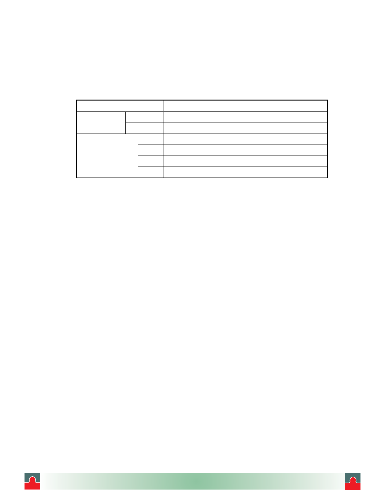
㩷㩷㩷㩷㩷㩷㩷㩷㩷Table 1.1㩷List of Accessories
Quantity
No. Part Name Type 1 pen 2 pen Remarks
㧝Chart paper H-10100 㧝㧝100 equal divisions
㧞Ribbon Cassette HPSROO1H0002C 㧝㧝
WPSR196A000001A 㧝㧝For 1 pen (Red)
㧟Cartridge Pen WPSR196A000002A 㧝 For 2 pen (Green)
㧠Mounting H4A14175 㧞㧞Panel mounting bracket
㧡Instruction HR72E 㧝㧝This manual
㧢Packing H4H14900 㧝㧝For IP65
䌛Note䌝
The ribbon cassette has been set in the instrument when this is shipped.
i
i
Tel: (01943) 602001 Fax: (01943) 816796

㵪7㵪
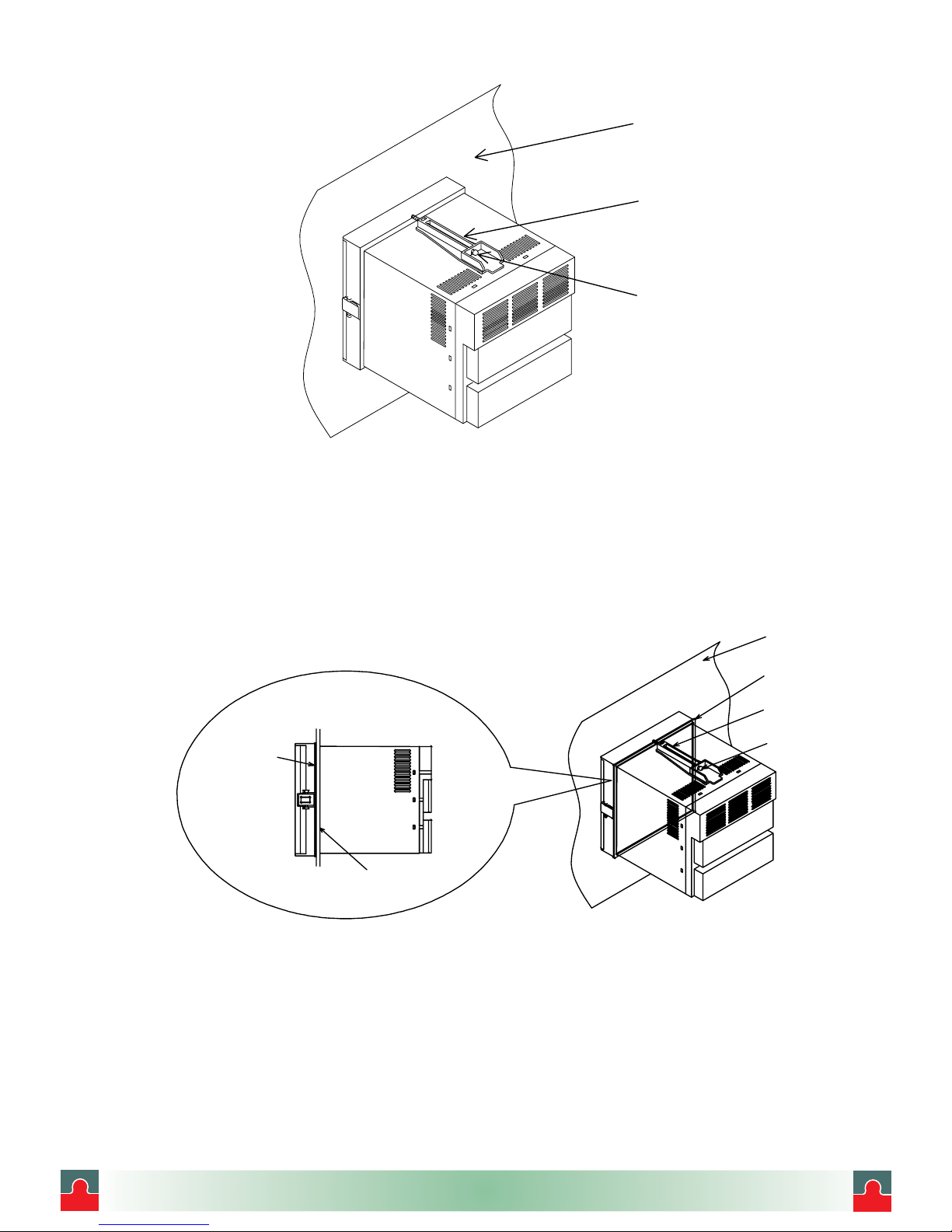
Take the chart holder out to check its accessories.
See Section 5.1 “Setting the Chart Paper” for pulling out the chart holder.
Fig. 1.2㩷Position of the Ribbon Cassette
Fig. 1.3㩷Position of the Chart Paper and the Cartridge Pen
The chart paper is contained in
the chart holder.
Open the Chart Guide to chec
k
it.
The cartridge pen is contained
in the storage chamber.
Open the chart cover to chec
k
it.
This instrument is shipped
with the ribbon cassette in
the back of the chart holder.
Chart Guide
Chart Cover
䌛Note䌝
ԘThis instrument is equipped with the ribbon cassette in back of the chart holder. Open the door
and pull out the chart holder to check it. (See Section 5.1 about taking out the chart holder.)
ԙThe chart paper and the cartridge pen are contained in the chart holder. Take the chart holder
out and open the chart cover to check it.
ԚMaximum angle of the door is 135 degrees when the door is fully open. Do not open the door
further, or the hinge will be broken.
i
i
Tel: (01943) 602001 Fax: (01943) 816796
㵪8㵪
1.2 Checking the Type and Specifications
A nameplate is put on the inside of the instrument. Remove the chart holder and make sure that the
nameplate is put in the middle far side of the instrument.
Make sure that this instrument meets your requested specification, seeing the following tables.
Table1.2 㩷Type
㧴㧾-㧣㧜غ㧘غغغ 㧝㧠㧠(㨃)㧝㧠㧠(㧴)㧝㧡㧜(㧰)mm
㧝㧝points
Measuring point 㧞㧞points
㧯㧡 Communication function (RS-485)
㧾㧱㧝 DI function
㧲㧸 Out of paper detection function
Options
㧸㧴㧟 Alarm output function
i
i
Tel: (01943) 602001 Fax: (01943) 816796
㵪9㵪
1.3 Temporary Storage
Store the instrument in the following environment.
When incorporated in the equipment, store it in the following environment as well.
1.4 Indication Card
An indication card has been affixed to the door upon delivery.㩷Enter a name as required.
㩷CAUTION㩷
Note that if a non-original nameplate㩷is attached, it may damage the door or mounting part.
㩷CAUTION㩷
Storage in a poor environment may damage the appearance, functions, and service life of the
instrument.
Storage Environment
䊶A place with little dust.
䊶A place free from combustible, explosive, or corrosive gases ( SO2, H2S, etc. ).
䊶A place free from vibrations or shocks.
䊶A place free from water or steam or high humidity ( 95% RH max. ).
䊶A place free from direct sunlight or high temperature ( 50㷄㩷 max. ).
䊶A place free from an extremely low temperature ( -20㷄min. ).
i
i
Tel: (01943) 602001 Fax: (01943) 816796

㵪10 㵪
CONSTRUCTION
Appearance
Fig. 2.1 Appearance
Cartridge pen
Door
Chart Holder
Display
keyboard
Terminal block
Case
Mounting bracket
Indication card
i
i
Tel: (01943) 602001 Fax: (01943) 816796
㵪11 㵪
2.2 Display Screen and Operation Keys
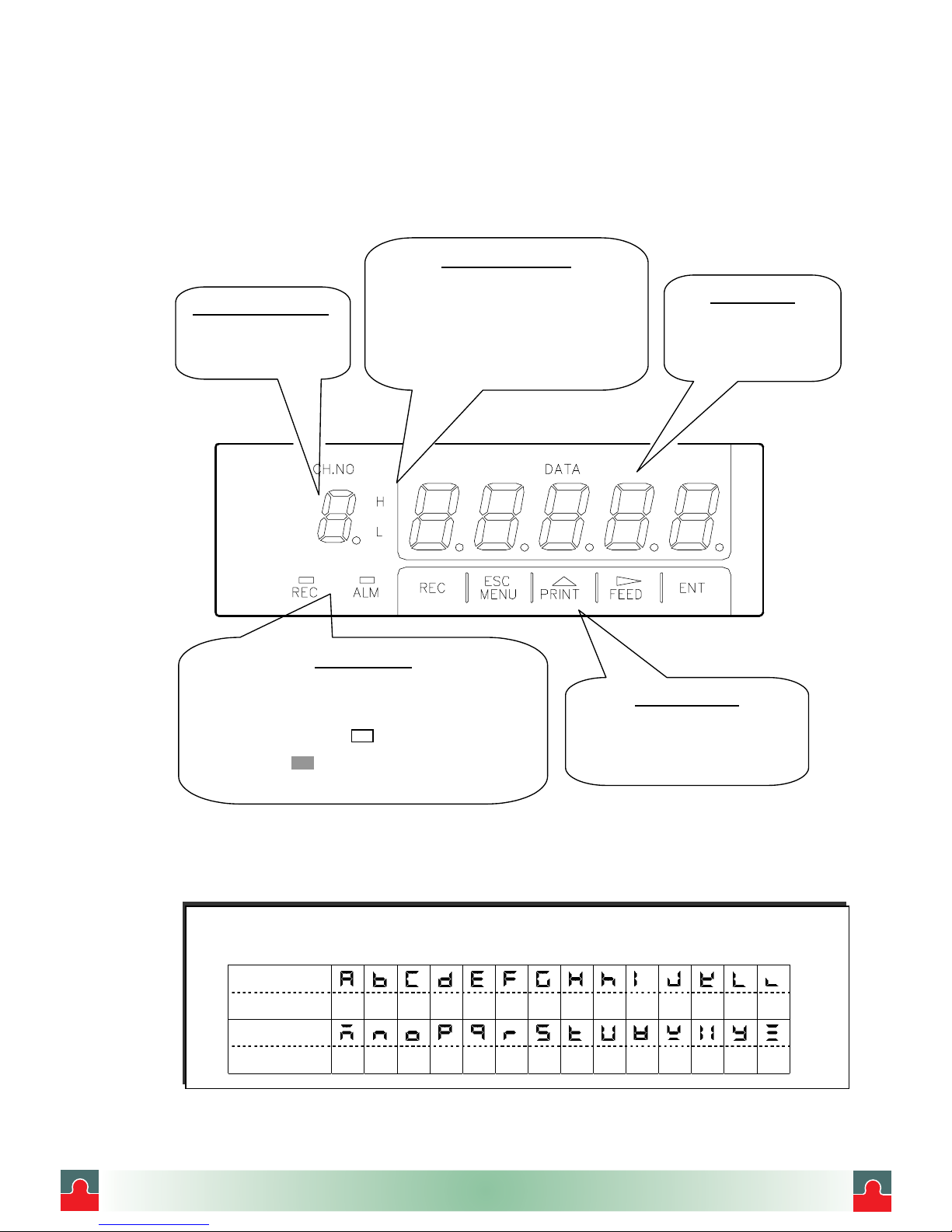
2.2.1 Display Screen
The following describes the display screen. Since the channel numbers and data are indicated by a
7-segment LED, alphabets are symbolized to represent them.
For the LED display, see " Symbolized Alphabets for Display" at [Reference] below.
Fig. 2.2 Display
䌛Reference䌝㩷 Symbolized Alphabets for Display
Display
Alphabet A B C
DE F G H 㨔I J K L 㨘
Display
Alphabet M N O P Q R S T U V W X Y Z
Alarm Type Display
Indicates alarm type in red.
"H" is lit when the alarm is High. And
“L” is illuminated when the alarm is
Low. Neither of them is illuminated
when there is no alarm.
Channel No. Display
Indicates channel
number in orange.
Data Display
Indicates the process
variable, time, setting
screen, etc. in orange.
Operation Keys
Use these keys for setting and
other operations.
Status Display
The "REC" lamp (orange) is lit when recording.
The "ALM" lamp (red) is illuminated when the alarm
is being activated. 㩷㩷 denotes that the lamp㩷
goes out and denotes that it is illuminated.
i
i
Tel: (01943) 602001 Fax: (01943) 816796
㵪12 㵪
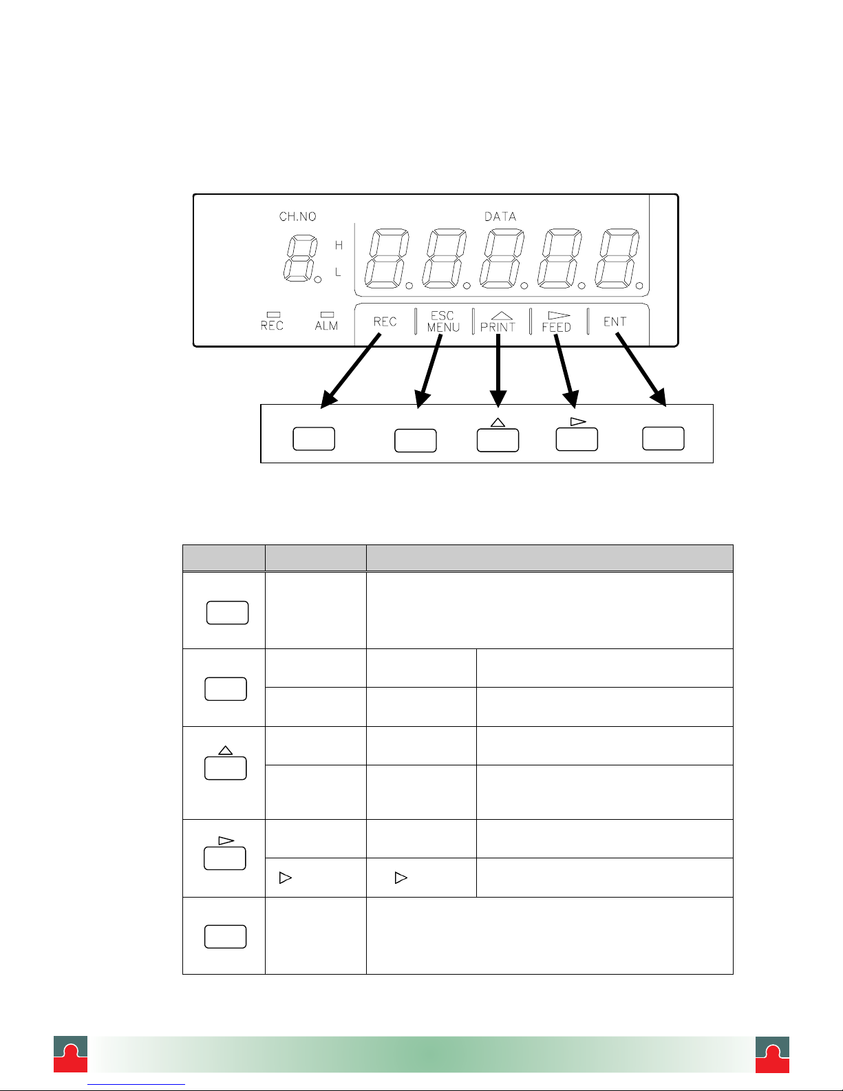
2.2.2 Operation Keys
The following describes the functions of each operation key.
The actual operation keys are represented as shown in the figure below in this manual.
㩷㩷㩷㩷㩷㩷㩷㩷㩷㩷㩷㩷㩷㩷㩷㩷Fig. 2.3 㩷Operation Keys in This Manual
Table2.1㩷Names of Operation Keys and Their Functions
Key Name Function
㵰REC㵱key
Starts/stops recording. To stop, press the “REC” key for 3
seconds or more. (Puts out the “REC” lamp.) To start,
press the “REC” key. (Lights the “REC” lamp.)
㵰MENU㵱key MENU
function
Selects engineering list print and
changes the mode to the setting mode.
㵰ESC㵱key ESC
function
Exits that menu halfway while selecting
a function.
㵰PRINT㵱key PRINT
function
Used to perform manual print or list
print.
㵰䂦㵱 key 䂦function
Used to select a setting parameter
(numeral or built-in
command)(ascending direction).
㵰FEED㵱key FEED
function
The chart paper is fed while the key is
pressed, and stopped when released.
㵰 㵱 key function Used to shift a digit in setting a
numeral.
㵰ENT㵱key
Used to register a setting parameter (numeral or built-in
command) after selecting it, or executing a function.
Pressing this key executes the setting.
REC
ENT
ESC
MENU
PRINT
FEED
REC PRINT FEED ENT
ESC
MENU
i
i
Tel: (01943) 602001 Fax: (01943) 816796

㵪13 㵪
INSTALLATION
3.1 External dimensions and panel cutout Dimensions
Unit㧦চ 㧨Front㧪㧨Rear㧪
㧨Side㧪㧨Panel cutout㧪
Fig. 3.1㩷External dimensions and panel cutout
㩷CAUTION㩷
For maintenance and using the instrument safely, it is recommended that spaces larger than the size
written in the bracket be secured per unit.
Dimensionrequired
when the door is full
y
opened (135ࠑ).
(Wall on the left side).
㧔㧕
㧔㧕
OCZ
㧔2CPPGNVJKEMPGUU
㧔㧕
OKP
OKP
.0
# %#% # %#% # %#%
$
$
#
$
$
#
$
$
#
$
$
#
$
$
#
$
$
#
5)
4&6&
&+
%1/
&+
&+
&+
i
i
Tel: (01943) 602001 Fax: (01943) 816796

㵪14 㵪
3.2 Mounting to the Panel
3.2.1 Procedure for Mounting to the Panel
1) Assemble the mounting bracket refering to Fig.3.2.
2) Insert this instrument through the front of the panel.
3) Hook the claws of the mounting bracket at the square holes in the top and bottom surfaces
of the case.
4) Tighten the screw of the mounting bracket with a screwdriver to attach it to the panel.
When the mounting unit does not move back and forth any more, tighten a screw by 180䉙.
Fig. 0.2㩷Mounting bracket
A
ssemble in such a manner tha
t
the screw nose will be almos
t
aligned with the plate surface. Mounting Claw
Body
Mounting
䌛Note䌝
If it is tightened with an excessive force, the case may be distorted and the mounting bracket may be
deformed. An adequate tightening torque is about 0.2 to 0.3 N䍃m (2䌾3䋗䌦䊶䋙).
㩷WARNING㩷
Do not install the instrument in a place exposed to a combustible, explosive, or corrosive gas (SO2,
H2S, etc.).
㩷CAUTION㩷
Install the instrument in the following places㩷㩷
䊶A place without rapid humidity change.
䊶A place of normal temperature (25㷄or so).
䊶A place exposed to as little mechanical vibrations as possible.
䊶A place with as little dusts as possible.
䊶A place affected by the electromagnetic field as little as possible.
䊶A place not directly exposed to high radiant heat.
䊶A place where the altitude is up to 2000m.
䊶Humidity has an effect on the chart paper and ink. Use the instrument in a humidity range of 20
to80%RH (60%RH is optimum).
䊶This instrument needs the inside installation.
Mounting to the Panel
䊶㩷A steel plate not thinner than 1.2mm is recommended as a mounting panel.
䊶㩷The maximum thickness of the mounting panel is 7mm.
Inclination
䊶㩷Install the instrument horizontally.
The instrument should be installed so that its inclination should be 0䉙at the front and within 30䉙at the
i
i
Tel: (01943) 602001 Fax: (01943) 816796
㵪15 㵪
Fig. 3.3㩷Mounting to the Panel
3.2.2 Mounting to the Panel in compliance with the IP65
Prior to mounting the instrument to the panel, attach packing to the position shown in the figure.
The rest of the procedure is the same.
Fig. 3.4㩷Mounting to the Panel䋨in compliance with the IP65䋩
Panel
Mounting
Screw
Mounting of Packing
Packing
Panel
Mounting bracket
Packing
Panel
Screw
i
i
Tel: (01943) 602001 Fax: (01943) 816796

㵪16 㵪
4. WIRING
4.1 Terminal arrangement and Power Wiring
4.1.1 Terminal arrangement
Fig. 4.1㩷Terminal Layout (Rear view)
4.1.2 Power Wiring
㩷WARNING㩷
㽲㩷 In order to prevent an electric shock, be sure to provide protective grounding prior to the power supply
to the instrument.
㽳㩷 Do not cut a protective grounding conductor or disconnect protective grounding.
㽴㩷 Make sure that the supply voltage for the instrument conforms to the voltage of the supply source.
㽵㩷 Attach a transparent protective cover prior to turning on the POWER of the instrument.
㽶㩷 Any interruption of the protective conductor inside or outside the instrument or disconnection of the
protective grounding terminal is likely to make the instrument dangerous under some fault conditions.
Intentional interruption is prohibited.
.0
%# # %#%
$
$
#
$
$
#5)
4&6&
&+
%1/ &+
&+
&+
Power source
terminal block
Communication
terminal block(RS-232C)
Input terminal block
Alarm output terminal block
(Option : LH3) Communication
terminal block (RS-485)
(Option : C5)
DI terminal block
(
O
p
tion : RE1
)
i
i
Tel: (01943) 602001 Fax: (01943) 816796

㵪17 㵪
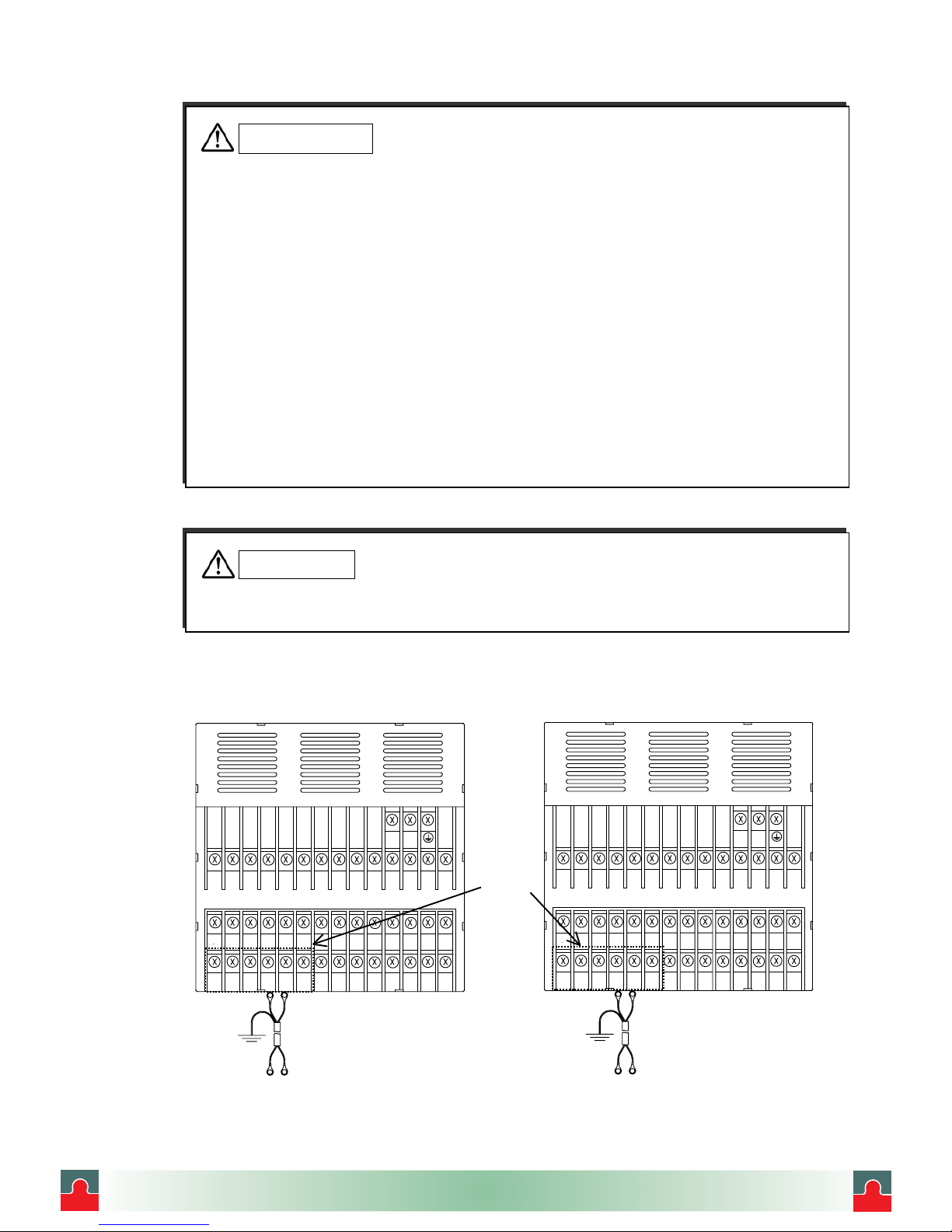
4.1.3 Wiring Procedure
1) Put your fingers on the left and right (both sides) hooks of the transparent protective cover on the
power source terminal block. Pushing them inside, pull out the cover to this side.
2) Connect the power source electric wire referring to Fig. 4.2. Connect the protective grounding to
㩷㩷㩷 the㩷㩷㩷 terminal. Connect the non-grounding side of the power source to "L" terminal. Connect
㩷㩷㩷the grounding side to the "N" terminal.
3) Put on the transparent protective cover.
4) Make sure that protective grounding is properly done.
㩷㩷㩷㩷㩷㩷㩷㩷㩷㩷㩷㩷㩷㩷㩷㩷㩷㩷㩷㩷㩷㩷㩷㩷㩷㩷㩷㩷㩷㩷㩷㩷㩷㩷㩷㩷㩷㩷㩷㩷㩷㩷㩷㩷㩷㩷Fig. 4.2㩷Power source Terminal block
㩷CAUTION㩷
㽲㩷 As an electric wire for the power source, use a 600 V vinyl insulated wire (IEC 227-3) or its equivalent
or above.
㽳㩷 Attach a round press-fitting terminal with insulated sleeve (for M3.5) to the end of the electric wire.
㽴㩷 Connect a protective grounding (resistance:100 㱅or lower, a minimum diameter of a grounding
conductor:1.6mm) to the protective grounding terminal.
㽵㩷 If other instrument shares the protective grounding conductor, there may be an effect caused by
noise coming from the grounding conductor. It is recommended not to share it with other instrument.
㽶㩷 In order to comply with the requirements of safety standard EN61010, the recorder shall have one of
the following as a disconnecting device, fitted within easy reach of the operator, and labeled as the
disconnecting device.
㩷䌡䋮A switch or circuit breaker which complies with the requirements of IEC60947-1, IEC60947-2 and 㩷
㩷㩷㩷IEC60947-3.
㩷䌢䋮A separable coupler which can be disconnected without the use of a tool.
㩷䌣䋮A separable plug, without a locking device, to mate with a socket outlet in the building.
㽷㩷 This product has been designed to conform to IEC1010-1 installation category 㸈and pollution
degree 2.
㧸㧺
CAUTION
The transparent protective cover should surely remove the left and right (both sides) hooks simultaneously.
If it removes by turns, there is a possibility that it may be damaged.
i
i
Tel: (01943) 602001 Fax: (01943) 816796
㵪18 㵪
4.2 Input Wiring
4.2.1 Wiring Procedure
1) Put your fingers on the left and right (both sides) hooks of the transparent protective cover on the
input terminal block. Pushing them inside, pull out the cover.
2) Wire the input lines referring to Fig. 4.3, Fig. 4.4 and Fig. 4.5(Page 19).
3) Put on the transparent protective cover.
Fig. 4.3㩷Input Wiring (For mV, V and Thermocouple inputs)
㩷CAUTION㩷
㽲Precautions for the input electric wire
㩷䊶See to it that no noise is mixed in input wiring. For input wiring, it is recommended a shielding wire or 㩷㩷㩷
㩷㩷twisted wire effective for noise be used.
㩷䊶In the case of thermocouple input, connect a thermocouple wire directly or use a compensating lead
㩷㩷wire. It is recommended a shielded input line be used.
㩷䊶In the case of resistance temperature detector input, dispersion of 3-wire line resistance should be less
㩷㩷than the below mentioned values. It is recommended to use a shielded input line.
㩷㩷㩷㩷㩷㩷㩷㩷㩷㩷㩷㩷㩷㩷㩷㩷㩷For Pt 100, JPt 100 䋻50m 㱅max.
㩷䊶When it is likely to be affected by induction noise, particularly when wiring near the high-frequency
㩷㩷power source, it is recommended a shielded twisted wire be used.㩷
㩷䊶Attach a round press-fitting terminal with insulated sleeve (for M3.5) to the end of the electric wire.
㽳Precautions for wiring
㩷䊶The wiring between the instrument and measurement point should be kept away from the power circuit
㩷㩷(25V or higher circuit or DO circuit).
㩷䊶Short-circuit unused input terminals. (Short-circuit between "䋫" and "䋭" in the case of mV, V, or
㩷㩷thermocouple input, and short-circuit among A, B, and B in the case of resistance temperature detector
㩷㩷input.)
㩷䊶Be sure to ground the shield of connecting wire.
䋨䋫䋩㩷㩷㩷㩷䋨䋭䋩 䋨䋫䋩㩷㩷㩷㩷䋨䋭䋩
.0
# %#% # %
$
$
#
$
$
#
5)
4&6&
&+
%1/ &+
&+
&+
.0
# %#% # %
$
$
#
$
$
#
5)
4&6&
&+
%1/ &+
&+
&+
Shielded wire Shielded wire
Ground Ground
DC voltage input Thermocouple input
Connecting lead wire Connecting compensating lead wire
Input
terminal
block
CAUTION
The transparent protective cover should surely remove the left and right (both sides) hooks simultaneously.
If it removes by turns, there is a possibility that it may be damaged.
i
i
Tel: (01943) 602001 Fax: (01943) 816796

㵪
19 㵪
Fig. 4.4㩷Input Wiring (For Resistance temperature detector)
Fig. 4.5㩷Input Wiring (For mA input)
㩷CAUTION㩷
㽲㩷 Attach the shunt resistor to the input terminal block of the instrument.
㽳㩷 A shunt resistor influences input accuracy. Use the following recommended resistor.
Resistance䋺250 㱅㩷 Rated power䋺1/4W Tolerance䋺㫧0.1% max.
㩷Temperature coefficient䋺㫧50ppm max.
.0
# %#% # %
$
$
#
$
$
#
5)
4&
6&
㧗㧙
&+
&+
&+
&+
%1/
$$#
Shielded wire
3-core cord
(Identical wire diameter length)
Ground
Resistance temperature detector
Input terminal block
Shielded wire
Ground
DC current input
Input terminal block
.0
# %#% # %
$
$
#
$
$
#
5)
4&
6&
㧗㧙
&+
&+
&+
&+
%1/
Shunt resistor
Connecting lead wire
i
i
Tel: (01943) 602001 Fax: (01943) 816796
Table of contents
Other Shinko Recording Equipment manuals


