SHO-ME 21.7662 User manual

SHO-ME@
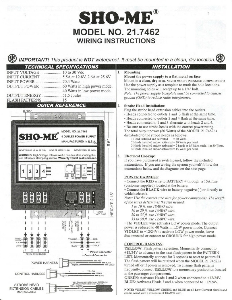
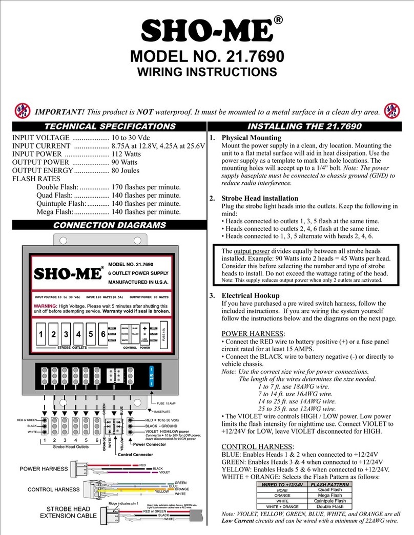
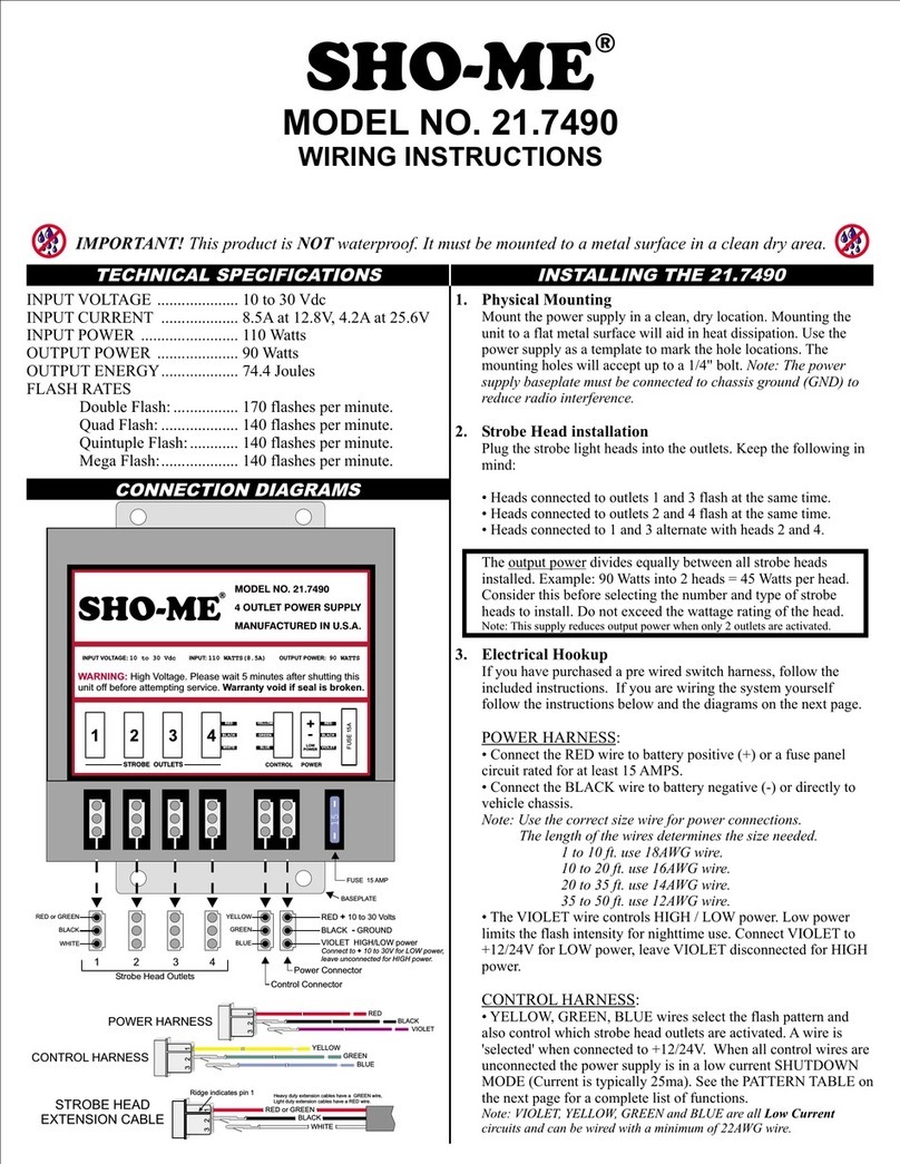
MODEL NO. 21.7662
WIRING INSTRUCTIONS
<I> IMPORTANT! Thisproduct is NOT waterproof. It must be mounted in aclean, dry location.<I>
TECHNICAL SPECIFICATIONS INSTALLATION
INPUT VOLTAGE 10to 30Vdc
INPUT CURRENT 5.5A at 12.8V,2.6A at 25.6V
INPUT POWER 70.4 Watts
OUTPUT POWER 60 Watts in high power mode.
40 Watts in low power mode.
OUTPUT ENERGY 51.5 Joules
FLASH PATTERNS 15
QUICK REFERENCE
I
I
I I I I I I
I I I I I I
++++++
~;;;;
11 2 3 4 5 61
StrobeHeadOutlets
f-'O: -"0: f-'O:
=>0 Wo =>0 I
~5 ~~ ~5
00 [jj~ 0I
~ 0 ~
()
I
I
+ +
YELLOW
!!RED
GREEN BLACK
BLUE VIOLET
ttPower Connector
Control Connector
RED "'
$]
GREEN
BLACK
WHIT
POWER HARNESS -REO ._BLACK
- VIOLET
M~ ~
CONTROL HARNESS YELLOW
-GREEN
-BLUE
M~ ~
STROBE HEAD
EXTENSION CABLES
(NOT INCLUDED)
H",y doly""'""0" oabl" h"s a GREEN wi".
Ughldoly""'""0" cabl"hm a RED wi,s.
RED or GREEN.
- BLACK
~WHITE
L
1. Mounting:
Mount the power supply to a flat metal surface.
Mountin a clean,dry area.NEVERMOUNTINENGINECOMPARTMENT!
Use the power supply as a template to mark the hole locations.
The mounting holes will accept up to a 1/4" bolt.
Note: The power supply baseplate must be connected to chassis
ground (GND) to reduce radio interference.
2. Strobe Head Installation:
Plug the strobe head extension cables into the outlets.
.Heads connected to outlets 1,3,5 flash at the same time.
.Heads connected to outlets 2, 4, 6 flash at the same time.
.Heads connected to 1,3,5 alternate with heads 2, 4,6.
. Be sure to use strobe heads with the correct power rating.
The total output power (60 Watts) of the MODEL 21.7662 is
distributed to the strobe heads as follows:
1Head installed and activated = 30 Watts.
2 Heads installed and/or activated =30 Watts per head.
3 Heads installed and/or activated = 2 heads at 15Watts each, 1at 30 Watts.
11Ieads installed and/or B£tiv~e<:I= 15 Watts per he~d~ - -
5 Heads installed and/or activated = 3 heads at 10Watts, 2 at 15Watts.
6 Heads installed and/or activated = 10Watts per head.
3. Electrical Hookup:
Ifyouhavepurchasedaswitchpanel,followthe included
instructions. If you are wiring the system yourself follow the
instructions below and the diagrams on the next page.
POWER HARNESS:
.Connect the RED wire to BATTERY + through a 15A fuse
(customer supplied) located at the battery.
.Connect the BLACK wire to battery negative (-) or directly to
vehicle chassis.
Note: Usethecorrectsizewirefor powerconnections.Thelength
of the wires determines the size needed.
1to 10ft. use 18AWGwire.
10 to 20ft. use 16AWG wire.
20 to 35ft. use 14AWG wire.
35 to 50ft. use 12AWG wire.
.The VIOLET wire activates LOW power mode. The output
power is reduced to 40 Watts in LOW power mode. Connect
VIOLET to +12/24Vto activate LOW power mode, leave
disconnected or connect to GROUND for high power mode.
CONTROL HARNESS:
WU([])'W: Flash pattern selection. Momentarily connect to
+12/24Vto advance to the next flash pattern in the PATTERN
LIST. Momentarily connect for 3 seconds to reset to pattern #1.
The flash pattern will be retained when the MODEL 21.7662 is
turned off or if power is removed. To change flash patterns
frequently, connect WJLJL([])'Wto a momentary pushbutton located
in the passenger compartment.
GREEN: Activates Heads 1 & 2 when connected to +12/24v.
BLUE: Activates Heads 3,4,5 and 6 when connected to +12/24v.
NOTE: VIOLET, YELLOW, GREEN, and BLUE are all Low Current circuits and
can be wired with a minimum of 18AWG wire.

ON/OFF and LOW POWER control.
WIRING DIAGRAM 1FLASH PATTERN SELECTION
Momentarily connect YELLOW wire to +l2/24V to advance to
the next flash pattern in the list below. (Or use pushbutton if you
installed one). The flash pattern loops back to pattern #1 when it
is advanced past #15. If you are unsure of which flash pattern is
currently selected, connect and hold YELLOW to +12/24V for 3
seconds to reset to flash pattern #1.
~f-
LOW ':'J
,POWER ~
:J; GREEN. BLUE
CONTROL HARNESS
Touch YELLOW to the terminal of the RED wire to select flash pattern.
Connect YELLOW to GROUND to ensure that flash pattern will never change.
:2JJGREEN, BLUE
CONTROL HARNESS
ON/OFF
SWITCH
DIAGNOSTIC INDICATORS
The MODEL 21.7662 is equipped with two
diagnostic indicators located on the PC board
directly below the EZ PANEL connector.
Ifthe MODEL21.7662hasstoppedfunctioning
check the diagnostic lights and follow the
INoDY6~~6R IN6~6~;ORinstructions below.
I . I OUTPUTINDICATOR(RED)
NORMAL: The OUTPUT INDICATOR will light when ANY strobe
head fires. It will blink inexact time with the flash pattern. When the
MODEL 21.7662 is turned off the indicator may dimly blink for a few
seconds. This indicates that the power supply is discharging itself.
-L
0 o--e.
PATTERN
SELECT
PROBLEM: Ifthe MODEL 21.7662 is activated but none of the strobe
heads are firing, check the OUTPUT INDICATOR. If the light is
blinking or on steady then it indicates that there is a short circuit on one
or more of the strobe head outputs.
To find the short circuit, unplug all strobe head cables from the
MODEL 21.7662. Test one cablelhead at a time until the problem is
found. Do not test with more than one cable/head installed.
The problem is typically at the strobe head end of the cable. If there is a
blue/green or black colored corrosion on the connector it is shorted.
Also checkfor a head or cable with a reverse wired connector.
WIRING DIAGRAM 3
SELECTIVE HEAD SWITCHING and PATTERN SELECT.
High Power mode.
YELLOW
CONTROL HARNESS
UJ
::>
-'
[!) I INPUT INDICATOR (GREEN)
NORMAL: The INPUT INDICATOR should NOT be lit during
normal operation. It may blink for a second when power is first applied
to the MODEL 21.7662, or when power is removed but this does not
indicate a problem with the power supply.
OUTLETS
1-2 z
UJ
UJ
a::
t:>
-L
0 o--e
PATTERN
SELECT PROBLEM: If the MODEL 21.7662 is activated but none of the strobe
heads are firing, check the INPUT INDICATOR. If it is ON then it
indicates that the input voltage is too low (below IOY).
There may be a bad connection to the battery or ground.
If the MODEL 21.7662 is functioning but the INPUT INDICATOR is
blinking or lit it indicates that the voltage is too low and the power
supply is not operating at full power. Check for bad connections and be
sure the proper size wire was used for the + and - connections.
!8:1 BLOWN FUSE
The MODEL 21.7662 will blow a fuse if the input voltage is reversed.
If this happens, fIrst locate the wiring fault, then replace the fuse with
one ofthe same rating. If the fuse continues to blow it indicates an
internal fault. Do not use a fuse larger than 15A!
EZ PANEL CONNECTOR
.The EZ PANEL connector is only for use with the EZ
PANEL series of control panels.
.Do not connect both the EZ PANEL cable and the
standard control wires at the same time!
.Do not connect any other devices to the EZ PANEL
connector as permanent damage may result.
.Use only approved cables with the EZ PANEL.
Other SHO-ME Power Supply manuals
Popular Power Supply manuals by other brands

Eaton
Eaton APS3-300 Installation and operation guide
Antec
Antec BP550 PLUS user manual

LifeSafety Power
LifeSafety Power FLEXPOWER RC75 Series installation manual
Delta Electronics
Delta Electronics DPS-300PB-1 Specifications
Oxford Instruments
Oxford Instruments NanoScience MercuryiPS Operator's manual

Thermaltake
Thermaltake TOUGHPOWER GF1 ARGB 850W user manual
