Sun Power SPS-G025 Series User manual

SPS-G025 Series User’s Menu
Please read this user's guide carefully before setup
Input:
1. Input range:
Universal full rangeAC 88V ~ 264V (47~ 63Hz) or DC 125V ~ 375V
2. Inrush current: When turn on input power source, there is peak current (inrush
current) running through filter capacitor of power supply. During power supply
operating, it is important not to turn off input power source and then immediately
turn on it again, otherwise, it may shorten power supply’s life.
Inrush current could be several to tens times of the normal current. It is important
to make sure input wiring, fuse and SW are able to carry inrush current.
Output:
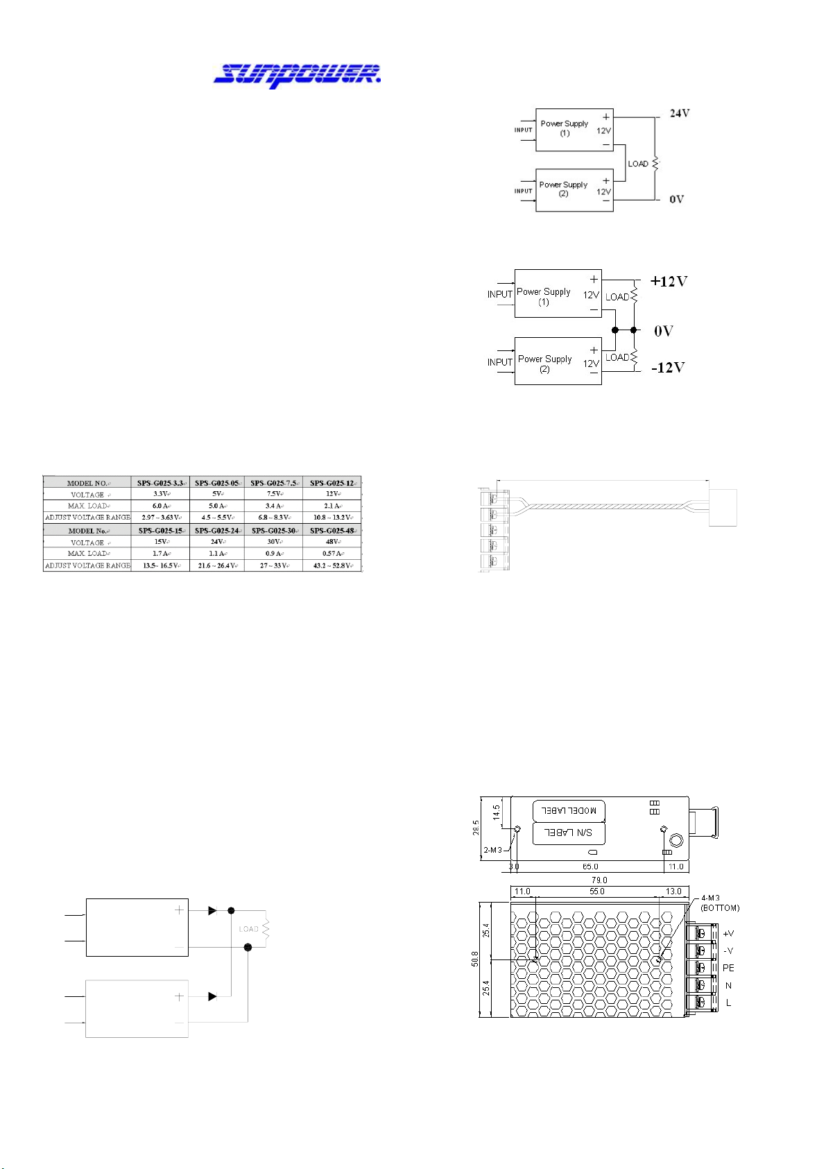
1.The output voltage adjustable range is ±10% of rated output voltage.As output
power is V0 x A0, when adjusting V0 to a higher value, should decrease A0as well,
ex.:
For SPS-G025-05, the rated output voltage is 5V, max output current is 5A: If
adjusting output voltage to 5.5V, should decrease max output current to 4.55Aas
well; and even if adjusting output voltage to 4.5V, max output should not be over
5A. (Note:Total output watts can’t over 25W)
2. Output rating :
Protection:
1. Short circuit protection :The power supply will go into “hiccup mode” against
Short circuit or overload conditions,and auto recovery while fault conditions are
removed.
2. Over load protection: When over loaded, power supply will “hiccup mode”.After
load reduced to meet rated range, power supply will recover automatically.
To Parallel Switching Power Supplies
Adjusting output voltage of each power supply to a same level, and then serialize
a diode after the positive pole of each power supply. The diode must be able to
carry current that higher than power supply’s max output, and should be
equipped with a proper heat sink. (It is suggested to choose a power supply
which max output could meet your system’s requirement instead of paralleling
lower output power supplies)
Operating temperature range : -20℃~ +70℃
( Derating factor 50℃~ 70℃: 2.5% / ℃)
ex: SPS-G025-05, the rated output voltage is 5V, max output current is 5A.
If working in 60℃, max output current is 3.75A.
Storage environment : 10% to 95% RH. (Non condensing)
INPUT Power Supply (1)
INPUT Power Supply (2)
D1
D2
To Serialize Switching Power Supplies:
a. To up rise output voltage:
b. To generate both positive and negative output voltage:
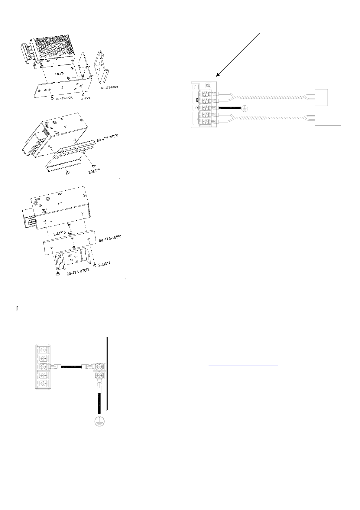
Wiring:
1. Output wiring must be thick and short enough to carry loading. The shorter and thicker
the wire, the less voltage it drops (less wire loss).
WIRE LOSS
L
N
PE
-V
+V
-V
+V
LOAD
2. Connecting PE of power supply to system’s chassis with a short & thick wire can
reduce noise and prevent electric shock.
Mounting:
1. Each power supply is enclosed with mounting screws. It is suggested to use enclosed
screws to setup power supply, otherwise, make sure its length must not be too long
(refer to the following drawing) to cause short circuit.
2. The input wiring should be separated fromoutput wiring to avoid noise interfere.
3. When multiple power supplies work together, be sure to keep proper distance
between power supply & power supply as well as power supply and the
environment for good air convection. Use extra cooling fans if needed.
A. Mounting holes dimension:
To keep the power supply working properly, do not block the vent holes as provide good
heat dissipation with air convection.

B. Din rail mounting: (contact your dealer for Din Rail brackets if needed)
Grounding :
g
thicker & short cable to connect between the Ground of the S.P.S.
& rack, to prevent noise & leakage safety.
L
N
PE
-V
+V
EQUIPMENT
CASE
Connection:
LOUT
IN
NPE-V+VADJ
V
-V
+V
LOAD
Power Source
AC/DC
Safety terms:
1. The Y capacitor inside power supply could deliver leakage current. When multiple
power supplies work in parallel or in series, the leakage current will increase to cause
the possibility of getting electric shock. Make sure ground wire is thick enough to
prevent the danger.
2. For AC input switching power supplies, the voltage running through primary circuit could
up to 2~4 times of AC input voltage. It is forbidden for non-technicians to open the
case. Contact your local dealer for technical support if needed.
3. The temperature inside power supplymay exceed 85℃(185℉) during full loading, so it
is dangerous to touch power supply at this time. Be sure to keep a proper distance
between power supply and combustible material.
Trouble Shooting:
If power supply couldn't work properly, please turn off input power SW, and check the
following steps:
1. Check all the connections (pin in/out correct? polarity correct? etc.)
2. Does terminal well connected? If not, reconnect it, and then turn on input power source
again.
3. Check load current. If over loaded, decrease loading, and then turn on input power
source again. (Rated load current show on label)
4. If there comes a sudden output interruption during adjusting VR, please turn VR to the
middle value, and then turn onAC power again.
5. If there is a temporary working followed by power supply shut down, it may cause by a
higher inrush current requirement of the system. Replace a higher output power supply
to meet the system’s requirement.
6. If environmental temperature gets too low or too high?
(1) If the environmental temperature lower than -20℃(-4℉) , take either of the
following steps:
a. Use heater to warm up the environment; or, b. Reduce loading.
(2) If environmental temperature higher than 50℃(122℉), use extra cooling fans to
enforce air convection, or reduce loading. (Refer to related specification)
7. If the fuse inside power supply melted, there must be something function abnormally.
Find out the abnormal cause and remove it; and then replace a new fuse. Make sure
the new fuse’s spec mustbe same as the original.
If all of the above items were checked and power supply still cannot
function normally, please contact your local dealer for support or
e-mail us: service@sunpower.com.tw. Also,for input / output
Specification,please visit www.sunpower.com.tw.
SUNPOWER TECHNOLOGY CORP. operates a policy of continuous development. Therefore, we
reserve the right to make changes and improvements to any of the products described in this guide
withoutpriornotice.
© SUNPOWER TECHNOLOGY CORP. All right reserved.
URL: http://www.sunpower.com.tw
April 3, 2009
VR1 for adjusting output voltage.
If there comes a sudden output
interruption during adjusting VR,
please turn VR1 to the middle
This manual suits for next models
8
Other Sun Power Power Supply manuals
Popular Power Supply manuals by other brands

alfatronix
alfatronix PR65R Operating & assembly instructions

IBM
IBM 9008-22L manual

SilverStone
SilverStone ST45SF Multilanguage manual

Delta Elektronika
Delta Elektronika ES300 Series manual

Altronix
Altronix AL400UL3 installation guide

Simco-Ion
Simco-Ion IQ Power HL Installation and operating instructions