Murrelektronik Emparro 20-3x360-500/24 User manual

(1) Allgemeines
Das Netzgerät enthält viele Besonderheiten, die bei Industrienetzgeräten zuvor nicht
gegeben waren. Es ist so konstruiert, daß es die üblichen Störfestigkeit im Industriebereich
ausgleicht und die Störaussendungen in Wohn- und Geschäftsbereichen garantiert.
Das Netzgerät hat die positive Eigenschaft, größere Anlauf- und Kurzschlußströme zu
liefern, so daß auch bestimmte Sicherungsautomaten auslösen.
Das Netzgerät enthält elektronische Schutzfunktionen für Überlast und beginnende
Überhitzung.
Wenn die Eingangsspannung für 4s bis auf 3 x 300 VAC abfällt, liegt die Ausgangsspannung
immer noch im Bereich der PLC Norm EN 61131-2 (≥20,4 VDC).
Verwendbar nur in Stern-Architektur TN, TT und IT Netzen.
Für den Einsatz in einer Umgebung mit Verschmutzungsgrad 2 (kontrollierte Umgebung).
(3) Ausrüstung
[1] Eingangsklemme:
Leitungsart
Starr 0,2 - 10 mm² / 24 - 8 AWG
Flexibel 0,2 - 6 mm² / 24 - 10 AWG
Flexibel mit Aderendhülse ohne Kunststoffhülse 0,2 - 6 mm² / 24 - 10 AWG
Flexibel mit Aderendhülse mit Kunststoffhülse 0,2 - 4 mm² / 24 - 12 AWG
Abisolierlänge 15 mm
Verwenden Sie Kupferleiter die für eine Mindestbetriebstemperatur von 75°C bei einer
Umgebungstemperatur von bis zu 60°C ausgelegt sind.
[2] Ausgangsspannungseinstellpoti 24 - 28 VDC.
[3] Zweifarbige LED, Ausgangsspannung “OK” – grün, Alarm – rot.
[4] Schalter für Parallelbetrieb. Schalter auf AN stellen, wenn Netzgeräte parallel
geschaltet werden. Werkseinstellung ist AUS.
[5] Potentialfreier Alarmkontakt (13/14),
max. Bemessungsgrößen 60 VDC / 80 mA (ohmsch) SELV.
Abisolierlänge 10 mm
[6] Ausgangsklemme:
Leitungsart
Starr 0,2 - 10 mm² / 24 - 8 AWG
Flexibel 0,2 - 6 mm² / 24 - 10 AWG
Flexibel mit Aderendhülse ohne Kunststoffhülse 0,2 - 6 mm² / 24 - 10 AWG
Flexibel mit Aderendhülse mit Kunststoffhülse 0,2 - 4 mm² / 24 - 12 AWG
Abisolierlänge 15 mm
Verwenden Sie Kupferleiter die für eine Mindestbetriebstemperatur von 75°C bei einer
Umgebungstemperatur von bis zu 60°C ausgelegt sind.
(4) Einbauart
Die Kühlung des Netzgerätes erfolgt durch natürliche Luftzirkulation. Beim Einbau ist
möglichst viel Platz für die Luftzirkulation zu lassen. Der obere und der untere Abstand
zu den anderen Geräten muß mindestens 40 mm betragen. Ein Seitenabstand von
min. 6 mm ist empfohlen, wenn ein benachbartes Gerät Wärme abstrahlt. Es ist zu
beachten, daß die Temperatur oberhalb der Geräte ca. 25°C höher ist als unterhalb.
Als Umgebungstemperatur der Geräte gilt die Temperatur direkt unterhalb des Gerätes.
Ist die Luftzirkulation beschränkt, muß zwangsbelüftet werden. Der Einbauplatz muß
den Anforderungen der EN 60950-1 Punkt 4.7 und 4.6.1 genügen. Gehäuseschutzklasse
IP20 (EN 60529).
(5) Einbau, Befestigungslöcher [9]
Die Schiene muß so befestigt werden, daß sie sich beim Ein- oder Ausbau des Gerätes
nicht verdreht. Einbauanweisung [7], Ausbauanweisung [8].
(6) Inbetriebnahme
Das Netzgerät ist als solches gebrauchsfertig; siehe Anschlußmöglichkeiten im Anhang.
Bei DC Eingangsspannung bitte das Diagramm [15] beachten.
(7) Belastbarkeit
Das Netzgerät muß mit der Schiene horizontal eingebaut werden, damit eine
ausreichende Kühlung gewährleistet ist. Der Nennstrom des Netzgerätes beträgt 20 A,
aber für den industriellen Einsatz können größere Ströme ohne Beschädigung oder
unnötiges Abschalten geliefert werden. Das Diagramm [10] zeigt die typische
Spannungs-/Strom- Kennlinie des Netzgerätes. Der abfallende Teil des Diagrammes
[10] zeigt die Strombegrenzung. Diagramm [11] zeigt die Temperatur- / Stromkurve
des Netzgerätes. Das Netzgerät ist dafür ausgelegt, eine Ausgangsleistung von 150%
(power boost) für eine Dauer von mindestens 5 Sekunden zu liefern [12].
(8) Parallelbetrieb [13]
Es ist möglich bis zu 3 Netzgeräte parallel zu schalten. Um eine gleichmäßige
Stromaufteilung zu erhalten, sind folgende Punkte einzuhalten.
1) Die Einzelspannungen der Netzgeräte sind genau aufeinander abzustimmen.
2) Die sekundärseitige Verdrahtung ist in Bezug auf Kabellänge und Querschnitt bis
zum Verbindungspunkt identisch auszuführen.
3) Stellen Sie den Schalter für Parallelbetrieb auf AN.
(9) Reihenbetrieb [14]
Es ist möglich, zwei Netzgeräte in Reihe zu schalten, so daß entweder 48 VDC oder
±24 VDC zur Verfügung stehen.
(10) Ausgangskurzschluß-Schutz
Zur ausgangsseitigen Stromüberwachung bis zu 28 VDC empfehlen wir die
Lastkreiskontrolle “MICO”. Bsp: MICO 4.10 Art. Nr. 9000-41034-0401000
Weitere Varianten: Auf Anfrage oder im Internet unter: www.murrelektronik.com
Für höhere Ausgangspannungen (Reihenschaltung) oder beim Einsatz von Standard
Sicherungsautomaten, kann das Netzgerät bei Kurzschluß z.B. folgende ABB
Sicherungsautomaten auslösen:
- S201-C3A
- S201-Z10A
Änderungen vorbehalten.
Lesen Sie diese Bedienungsanleitung vor Einbau
und Gebrauch des Netzgerätes aufmerksam
durch, damit Sie die besonderen
Gebrauchseigenschaften des Netzgerätes
nutzen können. Das Netzgerät enthält
Eigenschaften, die Ihnen zu mehr Zuverlässigkeit
in Ihrem System verhelfen. Bewahren Sie diese
Anleitung für einen möglichen späteren Gebrauch
auf.
Emparro 20-3x360-500/24
Art. Nr. 85692
BEDIENUNGSANLEITUNG
(2) Technische Spezifikationen, Art. Nr. 85692 V1.7
Nennspannung (L-L) 3 x 360 - 500 VAC
Spannungsbereich (L-L) 3 x 324 - 572 VAC
Nennspannung (L-N) 3 x 208 - 288 VAC
Spannungsbereich (L-N) 3 x 187 - 330 VAC
DC-Eingangsbetriebsnennspannung 500 - 700 VDC*
DC-Eingangsbetriebsspannungsbereich 450 - 745 VDC*
2-Phasen-Betriebsnennspannung 2 x 380 - 500 VAC
2-Phasen-Betriebsspannungsbereich 2 x 340 - 572 VAC
Nennfrequenz 50/60 Hz ±6%
Eingangsstrom, I
nen.
1,3 A / 3 x 360 VAC - 1,0 A / 3 x 500 VAC
Nennstrom mit zwei Phasen 2,1 A / 2 x 360 VAC
Einschaltstromstoß < 13 A / 3 x 500 VAC nach 1 ms
Wirkungsgrad, typ. 94,8% / 3 x 400 - 94,5% / 3 x 480 VAC
Leistungsfaktor typ. 0,75 / 3 x 400 VAC und 24 VDC / 20 A
Interne Sicherung 3 x 6,3 A (T)
Leitungsschutz extern 3 x 32 A (T)
Schutzklasse 1
Ausgangsspannung, einstellbar 24 - 28 VDC 24 VDC
Regelung +/-1%
Regelung, dynamisch, typ. 0 -> 100%, 5% 1 ms / 100% -> 5%, 5% 1 ms
Anlaufzeit, typ. < 400 ms
Netzausfallüberbrückungszeit > 20 ms / 3 x 400 VAC und 24 VDC / 20 A
Ausgangsstrom 24 VDC 20 A (+60°C) / 15,0 A (+70°C)
Ausgangsstrom 28 VDC 17,2 A (+60°C) / 12,8 A (+70°C)
Überlaststrom (power boost) 24 VDC 30 A / > 5 s
Kurzschluß, typ. 24 A
Restwelligkeit < 20 mV
rms
Einsatz als Akkuladegerät ja (mit fortschrittlichen Parallelbetrieb ON)
Überlastschutz / Überhitzungsschutz ja
Überspannungsauslöser Max. 31 VDC
Relative Feuchtigkeit 5 - 95%, keine Kondensation
Max. Umgebungstemperatur der Luft -40°C - +60°C (Derating 60°C-70°C)
Lagertemperatur -40°C - +85°C
Gehäuseschutzklasse, Gehäuse, EN 60529 IP 20
Abmessungen B x H x T; Gewicht 65 x 143 x 162 mm; 1,2 kg
* Der DC-Betrieb ist nicht UL-Zugelassen. Der Kunde muss einen geeigneten externen Schutz
installieren.
3x400 VAC
3x400 VAC
DC24V
13
PE
(DC +/ - 24V)
(DC +/ - 24V)
DC48V
14
3x400 VAC
3x400 VAC
PE
500-700 VDC
PE
+
-
L1
L2
L3
15
(+)
(-)
11
50% 100% 150%
12
0
5
10
15
20
25
30
-20 -10 0 10 20 30 40 50 60 70
24 V
28 V
Umgebungstemperatur [°C]
Ausgangsstrom [A]
7
8
SWITCHM ODE POWER SUPPLY
SWITCHMODEP OWERSUPPLY
ART.NO. 85692
ART. NO. 8569 2
INPUT:360 - 500VAC, 3W+PE, 50-60Hz 3x1.3A
INPUT:360-500VAC,3W+PE,50-60Hz3x1.3A
Emparro20-3x360-500/24
OUTPUT:24 VDC, 20 A, SELV
OUTPUT: 24 VDC, 20 A, SELV
IP20,t -25 ... +60 C
o
IP20, t -25 ... +60 C
o
CAUTION
CAUTION
-Read instruction manual before installation and use.
-Re ad ins tructi on manu al b efore i nstall ation and u se.
-Risk of electric shock. Do not open the case.
-Risk ofelectricshock.Donotopenthecase.
-No user serviceable parts inside.
-Nouserserviceablepartsinside.
!
!
ATTE NTIO N
ATTEN TI O N
-Reportez-vous aux instructions de service avant le
-Reportez-vousauxinstructionsdeserviceavantle
montageet la mise en service de l'appareil.
montageetlamiseen servicedel'appareil.
-Risque d'électrocution. Ne pas ouvrir l'appareil.
-Ri sque d' électr ocuti on. Ne p as ouvri r l' appareil .
-Ne contient pas de pièces interchangeables
-Ne conti ent pas de pièces i nterchangeables
parl'utilisateur
parl'utilisateur
Madein Czech Republic
MadeinCzechRepublic
potenti al fee alar m contac t
potentialfeealarmcontact
(NO - contac t 13 / 14)
(NO - contac t 13 /14 )
60VDC, 50 mA, SELV
60 VDC, 50 mA, S ELV
OFF- ON
OFF - ON
Parallelmode sw itch
Parallelmode switch
SWITCHM ODE POWER SUPPLY
SWITCHMODEPOWERSUPPLY
ART.NO. 85692
ART
.NO.85692
INPUT:360 - 500VAC, 3W+PE, 50-60Hz 3x1.3A
INPUT
:360-500VAC,3W+PE,50-60Hz3x1.3A
Emparro20-3x360-500/24
OUTPUT:24 VDC, 20 A, SELV
OUTPUT
:24VDC,20A,SELV
IP20,t -25 ... +60 C
o
IP20,t-25...+60C
o
CAUTION
CAUTION
-Read instruction manual before installation and use.
-Readinstructionmanualbeforeinstallationanduse.
-Risk of electric shock. Do not open the case.
-Riskofelectricshock.Donotopenthecase.
-Nouserserviceable parts inside.
-Nouserserviceablepartsinside.
!
!
!
ATTE NTIO N
ATTENTION
-Reportez-vous aux instructions de service avant le
-Reportez-vousauxinstructionsdeserviceavantle
montageet la mise en service de l'appareil.
montageetlamiseenservicedel'appareil.
-Risque d'électrocution. Ne pas ouvrir l'appareil.
-Risqued'électrocution.Nepasouvrirl'appareil.
-Ne contient pas de pièces interchangeables
-Necontientpasdepiècesinterchangeables
parl'utilisateur
parl'utilisateur
MadeinCzechRepublic
MadeinCzechRepublic
potenti al fee alar m contac t
potentialfeealarmcontact
(NO - contac t 13 / 14)
(NO-contact13/14)
60V DC, 50 m A, SELV
60VDC,50mA,SELV
OFF- ON
OFF-ON
Parallelmode sw itch
Parallelmodeswitch
8
0
4
8
12
16
20
24
28
32
0481216
20 24 28 32
dauernd
kurzfristig
10
Strom [A], (t = 60°C)
Spannung [V]
9
65
123123
123
61,5
61,5
143
OK / Alarm
OK / Al arm
Uout Adj. 24-28V
UoutAdj. 24-28V
Art. No. 85692
Art. No. 8569 2
13 14
13 14
L1
L1
L2
L2
L3
L3
INPUT Y 3x360-500VAC
50/60Hz
50/60Hz
1.3 - 1.0A
1.3 - 1.0A
OUTPUT:
OUTPUT:
Alarm
Alar m
24VDC / 20A
24VDC / 20A
Emparro
Emparro
1
2
3
56
4
OK / Alarm
OK / Alar m
Uout Adj. 24-28V
Uout Adj. 24-28V
Art. No. 85692
Ar t. N o. 8 56 92
13 14
13 14
L1
L1
L2
L2
L3
L3
INPUT Y 3x360-500V
INPUT Y 3x360-500V
50/60Hz
50/60Hz
1.3 - 1.0A
1.3 - 1.0A
OUTPUT:
OUTPU T:
Alarm
Alar m
24V / 20A
24V / 20A
Emparro
3 PHASE
®

(1) General
This unit employs many features previously unavailable in an industrial power supply. It has
been designed to withstand the high levels of interference found in heavy industry and has
emission levels low enough for it to be used in residential, commercial and light industrial
environments.
The Emparro 20-3x360-500/24 has a high level of reserve power. This enables loads with
significant inrush current to be supported and will also ensure that circuit breakers will trip in
event of short circuit.
A protective feature is provided which will take control as the unit approaches the power limit
due the overload or excessive temperature brought about by lack of ventilation.
If input voltage drops down to 3 x 300 VAC for 4 sec, output voltage still complies to PLC
standard EN 61131-2 (≥20,4 VDC).
Use only in star-architecture TN, TT and IT networks.
Only for use in pollution degree 2 environment (Controlled Environment).
(3) Features
[1] Input terminal:
Conductor sizes
Solid 0,2 -10 mm² / 24 - 8 AWG
Stranded 0,2 - 6 mm² / 24 - 10 AWG
Stranded with ferrule without plastic sleeve 0,2 - 6 mm² / 24 - 10 AWG
Stranded with ferrule with plastic sleeve 0,2 - 4 mm² / 24 - 12 AWG
Stripping length 15 mm
Use copper conductors that are designed for a minimum operating temperature of
75°C for ambient up to 60°C.
[2] Output voltage adjust 24 - 28 VDC.
[3] Bi-colour LED, output voltage “OK” - green, Alarm - red.
[4] Parallel mode switch, turn the switch to ON state when power supplies are
connected in parallel, factory setting is OFF.
[5] Potential free alarm contact (13/14),
max. ratings 60 VDC / 80 mA (resistive).
Stripping length 10 mm
[6] Output terminal:
Conductor sizes
Solid 0,2 - 10 mm² / 24 - 8 AWG
Stranded 0,2 - 6 mm² / 24 - 10 AWG
Stranded with ferrule without plastic sleeve 0,2 - 6 mm² / 24 - 10 AWG
Stranded with ferrule with plastic sleeve 0,2 - 4 mm² / 24 - 12 AWG
Stripping length 15 mm
Use copper conductors that are designed for a minimum operating temperature of
75°C for ambient up to 60°C.
(4) Location
The power supply is cooled by natural convection. Top and bottom clearances should be
40 mm at minimum. Min. 6 mm side clearance is recommended, if adjacent device is
generating heat. The ambient temperature should be measured on the underside of the
unit. There will be an increase of 25°C at the top. If natural convection is restricted, forced
cooling should be used. Mounting should comply with EN 60950-1 point 4.7 and 4.6.1.
Protection class of the case IP20 (EN 60529).
(5) Mounting [9]
The rail should be fixed solidly so that it cannot twist when mounting or removing the unit.
Mounting instructions [7], Removing instructions [8].
(6) Switching on
Factory set, ready to use, check the connection diagrams for parallel and series
connection. Check the connection diagram for DC use [15].
(7) Loading capacity
The nominal current is 20 A but due to the nature of industrial loading, the power supply
has been designed to support loads with high inrush currents without damage or
shutdown. Curve [10] shows the typical voltage / current curve. Decreasing part of the
curve [10] shows the current limitation. Curve [11] shows the typical overload /
temperature limit. To ensure correct convection cooling, the unit must always be mounted
with rail horizontally. Power supply is designed to give 150% output power (power boost)
for min. 5 seconds [12].
(8) Parallel connection [13]
Up to 3 units may be connected in parallel. The open circuit voltage of each unit should be
set to same value. Accuracy of setting will determine how well the units share the load
current. Turnparallel mode switch to ON state. The gauge and length of the cable between
each power supply and the common point should be the same.
(9) Series connection
Up to 2 units may be connected in series to give either 48 VDC or +/-24 VDC. Check the
connection diagram [14].
(10) Using circuit breakers on the power supply output:
Using circuit breakers on the power supply output side up to 28 VDC we recommend
“MICO”. For example: MICO 4.10, Art. No. 9000-41034-0401000.
More models on request or on our homepage: www.murrelektronik.com
For higher output voltages (series connection) and standard circuit breakers, power supply
will trip, for example the following ABB circuit breaker:
- S201-C3A
- S201-Z10A
We reserve the right to change this specification.
3 PHASE
®
In order to take the best advantage of the
features that this power supply has to offer
and to ensure long term reliability for your
equipment, please read these instructions
carefully before installation and use. They
should be retained for future reference.
Emparro 20-3x360-500/24
Art. No. 85692
OPERATING INSTRUCTIONS
(2) Technical specification, Art. No. 85692 V1.7
Nominal voltage (L-L) 3 x 360 - 500 VAC
Voltage range (L-L) 3 x 324 - 572 VAC
Nominal voltage (L-N) 3 x 208 - 288 VAC
Voltage range (L-N) 3 x 187 - 330 VAC
DC input operation nominal voltage 500 - 700 VDC*
DC input operation voltage range 450 - 745 VDC*
2-phase operation nominal voltage 2 x 380 - 500 VAC
2-phase operation voltage range 2 x 340 - 572 VAC
Nominal frequency 50/60 Hz ±6%
Input current, I
nom.
1,3 A / 3 x 360 VAC - 1,0 A / 3 x 500 VAC
Nominal current with two phases 2,1 A / 2 x 360 VAC
Inrush current < 13 A / 3 x 500 VAC after 1 ms
Efficiency, typ. 94,8% / 3 x 400 - 94,5% / 3 x 480 VAC
Power factor, typ. 0,75 / 3 x 400 VAC and 24 VDC / 20 A
Internal fuse 3x 6,3 A (T)
Branch Circuit Protection 3 x 32 A (T)
Safety class 1
Output voltage, adjustable 24 - 28 VDC 24 VDC
Static regulation accuracy +/-1%
Dynamic regulation accuracy typ. 0->100%, 5% 1ms / 100%->5%, 5% 1ms
Start-up time < 400 ms
Hold up time of the output > 20 ms / 3 x 400 VAC and 24 VDC / 20 A
Output current, continuous 24 VDC 20,0 A (+60°C) / 15,0 A (+70°C)
Output current, continuous 28 VDC 17,2 A (+60°C) / 12,8 A (+70°C)
Output current (power boost) 24 VDC 30 A / > 5 s
Output current, short circuit, typ. 24 A
Output ripple < 20 mV
rms
Usage as battery charger Yes (with advanced parallel mode ON)
Overloading / temperature protection Yes
Overvoltage shutdown Max. 31 VDC
Relative humidity 5 - 95% , no condensing
Max. surrounding air temperature -40°C - +60°C (derating 60°C - 70°C)
Storage temperature -40°C - +85°C
Protection class, case, EN 60529 IP20
Dimensions W x H x D; Weight 65 x 143 x 162 mm; 1,2 kg
* DC operation is not included to UL approval. Customer needs to use suitable external protection.
3x400 VAC
DC24V
13
PE
(DC+/-24V)
(DC +/ -24V)
DC48V
14
3x400 VAC
PE
500-700 VDC
PE
+
-
L1
L2
L3
15
(+)
(-)
11
50% 100% 150%
12
0
5
10
15
20
25
30
-20-100 10203040506070
24 V
28 V
Ambient temperature [°C]
Output current [A]
7
8
SWITCHMODE POWER S UPPLY
SWITCHMODE PO WER SUPPLY
ART.NO. 85692
ART. NO. 8569 2
INPUT:360 - 500VAC, 3W+PE, 50-60Hz 3x1.3A
Emparro20-3x360-500/24
OUTPUT:24 VDC, 20 A, SELV
OUTPUT: 24 VDC, 20 A, SELV
IP20,t -25 ... +60 C
o
IP20, t -25 ... +60 C
o
CAUTION
CAUTION
-Read instruction manual before installation and use.
-Re ad ins tructi on manu al be fore in stalla tion an d use.
-Risk of electric shock. Do not open the case.
-Risk ofelectricshock.Donotopenthecase.
-No user serviceable parts inside.
-No u ser s ervic eable p arts in side.
!
!
ATTENTION
ATTEN TI O N
-Reportez-vous aux instructions de service avant le
-Reportez-vousauxinstructionsdeserviceavantle
montageet la mise en service de l'appareil.
montage et la mise en s ervi ce de l' appar eil.
-Risque d'électrocution. Ne pas ouvrir l'appareil.
-Ri sque d' électr ocuti on. Ne p as ouvri r l'ap pareil .
-Ne contient pas de pièces interchangeables
-Ne conti ent pas de pièces in terchangeables
parl'utilisateur
parl'utilisateur
Madein Czech Republic
MadeinCzechRepublic
potenti al fee alarm cont ac t
potentialfeealarmcontact
(NO - contac t 13 / 14)
(NO - contac t 13 /14 )
60VD C, 50 m A, SELV
60 VDC , 50 m A, SELV
OFF- ON
OFF - ON
Parallelmode sw itch
Parallelmode switch
SWITCHMODE POWER SUPPLY
SWITCHMODEPOWERSUPPLY
ART.NO. 85692
ART
.NO.85692
INPUT:360 - 500VAC, 3W+PE, 50-60Hz 3x1.3A
INPUT
:360-500VAC,3W+PE,50-60Hz3x1.3A
Emparro20-3x360-500/24
OUTPUT:24 VDC, 20 A, SELV
OUTPUT
:24VDC,20A,SELV
IP20,t -25 ... +60 C
o
IP20,t-25...+60C
o
CAUTION
CAUTION
-Read instruction manual before installation and use.
-Readinstructionmanualbeforeinstallationanduse.
-Risk of electric shock. Do not open the case.
-Riskofelectricshock.Donotopenthecase.
-No user serviceable parts inside.
-Nouserserviceablepartsinside.
!
!
!
ATTENTION
ATTENTION
-Reportez-vous aux instructions de service avant le
-Reportez-vousauxinstructionsdeserviceavantle
montageet la mise en service de l'appareil.
montageetlamiseenservicedel'appareil.
-Risque d'électrocution. Ne pas ouvrir l'appareil.
-Risqued'électrocution.Nepasouvrirl'appareil.
-Ne contient pas de pièces interchangeables
-Necontientpasdepiècesinterchangeables
parl'utilisateur
parl'utilisateur
MadeinC
zechRepublic
MadeinCzechRepublic
potentialf ee alar m contac t
potentialfeealarmcontact
(NO- con tac t 13 / 14)
(NO-contact13/14)
60VD C, 50 mA, SELV
60VDC,50mA,SELV
OFF- ON
OFF-ON
Parallelmode sw itch
Parallelmodeswitch
10
0
4
8
12
16
20
24
28
32
0481216
20 24 28 32
continuous
short-term
Current [A], (t = 60°C)
Voltage [V]
9
65
123123
123
61,5
61,5
143
OK / Alarm
OK / Al arm
Uout Adj. 24-28V
UoutAdj. 24-28V
Art. No. 85692
Art. No. 8569 2
13 14
13 14
L1
L1
L2
L2
L3
L3
INPUT Y 3x360-500VAC
50/60Hz
50/60Hz
1.3 - 1.0A
1.3 - 1.0A
OUTPUT:
OUTPUT:
Alarm
Alar m
24VDC / 20A
24VDC / 20A
Emparro
Emparro
1
2
3
56
4
OK / Alarm
OK / Alar m
Uout Adj. 24-28V
Uout Adj. 24-28V
Art. No. 85692
Ar t. N o. 8 56 92
13 14
13 14
L1
L1
L2
L2
L3
L3
INPUT Y 3x360-500V
INPUT Y 3x360-500V
50/60Hz
50/60Hz
1.3 - 1.0A
1.3 - 1.0A
OUTPUT:
OUTPU T:
Alarm
Alarm
24V / 20A
24V / 20A
Emparro

(1) Généralités
Cette alimentation comprend plusieurs nouvelles caractéristiques de protection qui
n’existaient pas auparavant. Elle a été conçue pour supporter des interférences de forte
intensité que l’on rencontre dans l’industrie. L’émission et l’immunité aux perturbations
électromagnétiques, répondent aux normes les plus restrictives de l’industrie et du tertiaire.
Cette alimentation délivre un courant de sortie dynamique très élevé en cas de surcharge
ou de court circuit afin de créer une sélectivité au niveau des disjoncteurs en aval.
Elle intègre une protection électronique en cas de surcharge ou de surchauffe.
La tension d’entrée peut descendre jusqu’à 3 x 300 VAC pendant 4 secondes et donc
la tension de sortie est alors dans la norme de l’automate programmable standard selon
EN 61131-2 (≥20,4 VDC).
Utilisation uniquement avec une architecture en étoile dans les réseaux TT, TN et IT.
Pour une utilisation dans un environnement de pollution de degré 2 (environnement
contrôlé).
(3) Caractéristiques
[1] Bornes d’entrée:
Section du câble
Fil rigide 0,2 - 10 mm² / 24 - 8 AWG
Fil souple 0,2 - 6 mm² / 24 - 10 AWG
Fil souple avec embout non isolé 0,2 - 6 mm² / 24 - 10 AWG
Fil souple avec embout isolé 0,2 - 4 mm² / 24 - 12 AWG
Longueur de dénudage 15 mm
Utiliser des conducteurs en cuivre acceptant des températures de fonctionnement de
75°C et ambiante de 60°C.
[2] Potentiomètre de réglage de la tension de sortie de 24 à 28 VDC.
[3] LED bicolore, tension de sortie “OK” – vert, Alarm – rouge.
[4] Interrupteur de mode parallèle, positionner l’interrupteur sur ON lors d’un
branchement en parallèle, la valeur d’usine par défaut est OFF.
[5] Contact sec d’alarme (13/14),
valeurs maxi 60 VDC / 80 mA (charge résistive) SELV.
Longueur de dénudage 10 mm
[6] Bornes de raccordement:
Section du câble
Fil rigide 0,2 - 10 mm² / 24 - 8 AWG
Fil souple 0,2 - 6 mm² / 24 - 10 AWG
Fil souple avec embout non isolé 0,2 - 6 mm² / 24 - 10 AWG
Fil souple avec embout isolé 0,2 - 4 mm² / 24 - 12 AWG
Longueur de dénudage 15 mm
Utiliser des conducteurs en cuivre acceptant des températures de fonctionnement de
75°C et ambiante de 60°C.
(4) Emplacement
L’alimentation est refroidie par convection naturelle. Il est important de maintenir un
espace autour de l’alimentation pour garantir son fonctionnement et sa fiabilité. L’espace
libre au dessus et en dessous de l’alimentation doit être au minimum de 40 mm. En
cas de source de chaleur adjacente, prévoir un écart d’au moins 6 mm. La température
ambiante doit être mesurée en dessous de l’alimentation. La température sur le dessus
de l’alimentation est supérieure d’environ 25°C. Si la convection naturelle est limitée,
prévoyez un refroidissement par circulation d’air forcée. Lors du montage de
l’alimentation, conformez-vous à la norme EN 60950-1, points 4.7, 4.6.1. Indice de
protection IP20 (EN 60529).
(5) Montage [9]
Le rail doit être solidement fixé pour éviter sa torsion au moment du montage et du
démontage de l’alimentation. Instructions de montage [7], Instructions de démontage
[8].
(6) Mise en route
L’alimentation est réglée au départ de l’usine et prête à fonctionner. Vérifier le schéma
de raccordement pour une utilisation en DC [15].
(7) Limite de charge
L’alimentation doit être montée sur un rail DIN horizontal. Le courant nominal est de
20 A, mais l’alimentation a été conçue pour supporter des charges ayant d’importants
appels de courant sans que cela ne l’endommage ou ne l’arrte. La figure [10] montre
une courbe type tension/courant. La courbe [11] représente le courant nominal de
l’alimentation en fonction de la température ambiante. Cette alimentation a été conçue
pour délivrer 150% de puissance en sortie (power boost) pendant min. 5 secondes
[12].
(8) Montage en parallèle [13]
Trois unités peuvent être raccordées en parallèle. Pour assurer une répartition homogène
du courant, les points suivant sont à respecter: 1) La tension à vide des différents
appareils doit être strictement identique. 2) Le raccordement du secondaire doit être
réalisé avec des longueurs et des sections de cábles identiques pour tous les appareils.
3) Passez l’interrupteur de mode parallèle sur ON.
(9) Montage en série
Deux unités au maximum peuvent être raccordées en série pour obtenir soit 48 VDC,
soit +/- 24 VDC. Reportez vous au schéma de raccordement [14].
(10) Protection contre les courts-circuits à la sortie:
Pour des tensions d’alimentations jusqu’à 28 VDC, nous vous préconisons notre
protection “MICO”. Par exemple : MICO 4.10, réf. 9000-41034-0401000
Autres variantes : nous consulter ou disponibles sur notre site: www.murrelektronik.fr
Pour des tensions de sortie plus élevées (connexion en série) ou des installations
équipées de disjoncteurs standards, l’alimentation peut, en cas de court-circuit,
déclencher les disjoncteurs ABB suivants :
- S201-C3A
- S201-Z10A
Nous nous réservons le droit de modifier ces spécifications sans préavis.
3 PHASE
®
Pour vous permettre de profiter au maximum
des caractéristiques de cette alimentation,
nous vous conseillons de lire attentivement
ces instructions avant son montage et sa mise
en service. Conservez ces documents pour
une consultation future.
Emparro 20-3x360-500/24
Ref.: 85692
Instructions de service
(2) Caractéristiques techniques, Ref. 85692 V1.7
Tension nominale (L-L) 3 x 360 - 500 VAC
Plage de tension d’entrée(L-L) 3 x 324 - 572 VAC
Tension nominale (L-N) 3 x 208 - 288 VAC
Plage de tension d’entrée (L-N) 3 x 187 - 330 VAC
Tension nominale de fonctionnement de l’entrée CC 500 - 700 VDC*
Plage de tension de fonctionnement de l’entrée CC 450 - 745 VDC*
Tension nominale de fonctionnement biphasée 2x380-500VAC
Plage de tension de fonctionnement biphasée 2x340-572VAC
Fréquence nominale 50/60 Hz ±6%
Courant nominal, Inom 1,3 A / 3 x 360 VAC - 1,0 A / 3 x 500 VAC
Courant nominal avec deux phases 2,1 A / 2 x 360 VAC
Courant d’appel < 13 A / 3 x 500 VAC ensuite 1 ms
Rendement,typ 94,8%/3x400-94,5%/3x480VAC
Facteur de puissance, typ 0,75 / 3 x 400 VAC - 24 VDC / 20 A
Fusible interne 3 x 6,3 A (T)
Fusible externe 3 x 32 A (T)
Classe de protection 1
Tension de sortie, ajustable 24 - 28 VDC 24 VDC
Régulation tension de sortie +/-1%
Régulation dynamique 0->100%, 5% 1ms / 100%->5%, 5% 1ms
Temps de départ < 400 ms
Tempsdemaintient >20ms/3x400VAC-24VDC/20A
Courant 24 VDC 20 A (+60°C) / 15,0 A (+70°C)
Courant 28 VDC 17,2 A (+60°C) / 12,8 A (+70°C)
Courant de surcharge (power boost) 24 VDC 30 A / > 5 s
Courant de court circuit typ. 24 A
Ondulation résiduelle < 20 mV
rms
Utilisation en chargeur de batterie Oui (en mode parallèle avancé activé)
Dispositif de protection surcharge/surchauffe Oui
Protection des surtensions Max. 31 VDC
Humidité relative 5 - 95% , sans condensation
Température maximale de l’environnement immédiat -40°C - +60°C (déclassement entre 60°C et 70°C)
Température de stockage -40°C - +85°C
Indice de protection, EN 60529 IP20
Dimensions L x H x P; Poids 65 x 143 x 162 mm; 1,2 kg
* L’homologation UL n’inclut pas l’utilisation en mode DC. Le client doit utiliser une protection externe
appropriée.
3x400 VAC
DC24V
13
PE
(DC+/-24V)
(DC +/ -24V)
DC48V
14
3x400 VAC
PE
500-700 VDC
PE
+
-
L1
L2
L3
15
(+)
(-)
11
50% 100% 150%
12
0
5
10
15
20
25
30
-20-10 0 10203040506070
24 V
28 V
Température ambiante [°C]
Courant de sortie [A]
7
8
SWITCHMODE POWER S UPPLY
SWITCHMODE PO WER SUPPLY
ART.NO. 85692
ART. NO. 8569 2
INPUT:360 - 500VAC, 3W+PE, 50-60Hz 3x1.3A
Emparro20-3x360-500/24
OUTPUT:24 VDC, 20 A, SELV
OUTPUT: 24 VDC, 20 A, SELV
IP20,t -25 ... +60 C
o
IP20, t -25 ... +60 C
o
CAUTION
CAUTION
-Read instruction manual before installation and use.
-Re ad ins tructi on manu al be fore in stalla tion an d use.
-Risk of electric shock. Do not open the case.
-Risk ofelectricshock.Donotopenthecase.
-No user serviceable parts inside.
-No u ser s ervic eable p arts in side.
!
!
ATTENTION
ATTEN TI O N
-Reportez-vous aux instructions de service avant le
-Reportez-vousauxinstructionsdeserviceavantle
montageet la mise en service de l'appareil.
montage et la mise en s ervi ce de l' appar eil.
-Risque d'électrocution. Ne pas ouvrir l'appareil.
-Ri sque d' électr ocuti on. Ne p as ouvri r l'ap pareil .
-Ne contient pas de pièces interchangeables
-Ne conti ent pas de pièces in terchangeables
parl'utilisateur
parl'utilisateur
Madein Czech Republic
MadeinCzechRepublic
potenti al fee alarm cont ac t
potentialfeealarmcontact
(NO - contac t 13 / 14)
(NO - contac t 13 /14 )
60VD C, 50 m A, SELV
60 VDC , 50 m A, SELV
OFF- ON
OFF - ON
Parallelmode sw itch
Parallelmode switch
SWITCHMODE POWER SUPPLY
SWITCHMODEPOWERSUPPLY
ART.NO. 85692
ART
.NO.85692
INPUT:360 - 500VAC, 3W+PE, 50-60Hz 3x1.3A
INPUT
:360-500VAC,3W+PE,50-60Hz3x1.3A
Emparro20-3x360-500/24
OUTPUT:24 VDC, 20 A, SELV
OUTPUT
:24VDC,20A,SELV
IP20,t -25 ... +60 C
o
IP20,t-25...+60C
o
CAUTION
CAUTION
-Read instruction manual before installation and use.
-Readinstructionmanualbeforeinstallationanduse.
-Risk of electric shock. Do not open the case.
-Riskofelectricshock.Donotopenthecase.
-No user serviceable parts inside.
-Nouserserviceablepartsinside.
!
!
!
ATTENTION
ATTENTION
-Reportez-vous aux instructions de service avant le
-Reportez-vousauxinstructionsdeserviceavantle
montageet la mise en service de l'appareil.
montageetlamiseenservicedel'appareil.
-Risque d'électrocution. Ne pas ouvrir l'appareil.
-Risqued'électrocution.Nepasouvrirl'appareil.
-Ne contient pas de pièces interchangeables
-Necontientpasdepiècesinterchangeables
parl'utilisateur
parl'utilisateur
MadeinCzech Republic
MadeinCzechRepublic
potenti al fee alarm cont ac t
potentialfeealarmcontact
(NO - contac t 13 / 14 )
(NO-contact13/14)
60VD C, 50 m A, SELV
60VDC,50mA,SELV
OFF- ON
OFF-ON
Parallelmode sw itch
Parallelmodeswitch
0
4
8
12
16
20
24
28
32
0481216
20 24 28 32
10
continu
court terme
Courant [A], (t = 60°C)
Tension [V]
9
65
123123
123
61,5
61,5
143
OK / Alarm
OK / Al arm
Uout Adj. 24-28V
UoutAdj. 24-28V
Art. No. 85692
Art. No. 8569 2
13 14
13 14
L1
L1
L2
L2
L3
L3
INPUT Y 3x360-500VAC
50/60Hz
50/60Hz
1.3 - 1.0A
1.3 - 1.0A
OUTPUT:
OUTPUT:
Alarm
Alar m
24VDC / 20A
24VDC / 20A
Emparro
Emparro
1
2
3
56
4
OK / Alarm
OK / Alar m
Uout Adj. 24-28V
Uout Adj. 24-28V
Art. No. 85692
Ar t. N o. 8 56 92
13 14
13 14
L1
L1
L2
L2
L3
L3
INPUT Y 3x360-500V
INPUT Y 3x360-500V
50/60Hz
50/60Hz
1.3 - 1.0A
1.3 - 1.0A
OUTPUT:
OUTPU T:
Alarm
Alarm
24V / 20A
24V / 20A
Emparro

(1) General
Este tipo de fuente presenta muchas funcionalidades no disponibles con anterioridad en fuentes
de alimentación con aplicación en la industria. Es capaz de soportar altos niveles de interferencia,
como suele ocurrir en ambientes industriales y presenta unos niveles de emisión suficientemente
bajos como para ser usada en ámbitos comerciales y residenciales.
La fuente Emparro 20-3x360-500/24 presenta un alto nivel de potencia. Esto permite soportar
cargas que provoquen altas corrientes de puesta en marcha y asegura asimismo una correcta
actuación sobre circuitos o interruptores de protección en caso de cortocircuito.
Está provista de una característica de protección que asume el control a medida que la fuente se
aproxima a su límite de potencia, en caso de sobrecarga o de una excesiva temperatura por falta
de ventilación.
El voltaje de entrada puede descender hasta 3 x 300 VAC durante 4 segundos por lo que la salida
sigue el estándar de PLC EN 61131-2 (≥20,4 VDC).
Para uso en estructuras de redes TN, TT y IT.
Para uso en ambientes con grado 2 de contaminación (Ambiente Controlado).
(3) Características
[1] Bornes de entrada:
Rendimiento
Rígido 0,2 - 10 mm² / 24 - 8 AWG
Flexible 0,2 - 6 mm² / 24 - 10 AWG
Flexible con embocadura sin cubierta de plástico 0,2 - 6 mm² / 24 - 10 AWG
Flexible con embocadura con cubierta de plástico 0,2 - 4 mm² / 24 - 12 AWG
Longitud de pelado 15 mm
Utilice conductores de cobre que estén diseñados para soportar temperaturas de 75ºC para
temperatura ambiente de 60ºC.
[2] Ajuste del voltaje de salida: 24 - 28 VDC.
[3] LED Bi-color, salida de tensión ”OK” – verde, Alarm – rojo.
[4] Modo de conmutación en paralelo, coloque el switch en posición ON cuando las fuentes
de alimentación estén conectadas en paralelo, para los ajustes de fábrica es OFF.
[5] Contacto de alarma libre de potencial (13/14),
valor max. 60 VDC / 80 mA (resistivo) SELV.
Longitud de pelado 10 mm
[6] Bornes de salida:
Rendimiento
Rígido 0,2 - 10 mm² / 24 - 8 AWG
Flexible 0,2 - 6 mm² / 24 - 10 AWG
Flexible con embocadura sin cubierta de plástico 0,2 - 6 mm² / 24 - 10 AWG
Flexible con embocadura con cubierta de plástico 0,2 - 4 mm² / 24 - 12 AWG
Longitud de pelado 15 mm
Utilice conductores de cobre que estén diseñados para soportar temperaturas de 75ºC para
temperatura ambiente de 60ºC.
(4) Emplazamiento
La fuente de alimentación es ventilada de forma natural por convección. Es importante
mantener un espacio libre respecto otros componentes para un mejor y largo período de
funcionamiento y estabilidad. Por la parte superior e inferior, el espacio libre debería de ser de
40 mm como mínimo. Se recomienda un mínimo de 6 mm de espacio si el equipo adyacente
genera calor. La temperatura ambiente se ha de medir en la parte inferior de la fuente mientras
que se produce un aumento de 25°C en la parte superior de ésta. Si la ventilación natural
estuviera limitada, se tendría que usar una ventilación forzada. El montaje ha de cumplir con el
punto 4.7 y 4.6.1 de EN 60950-1. Clase de protección del chasis IP20 (EN 60529).
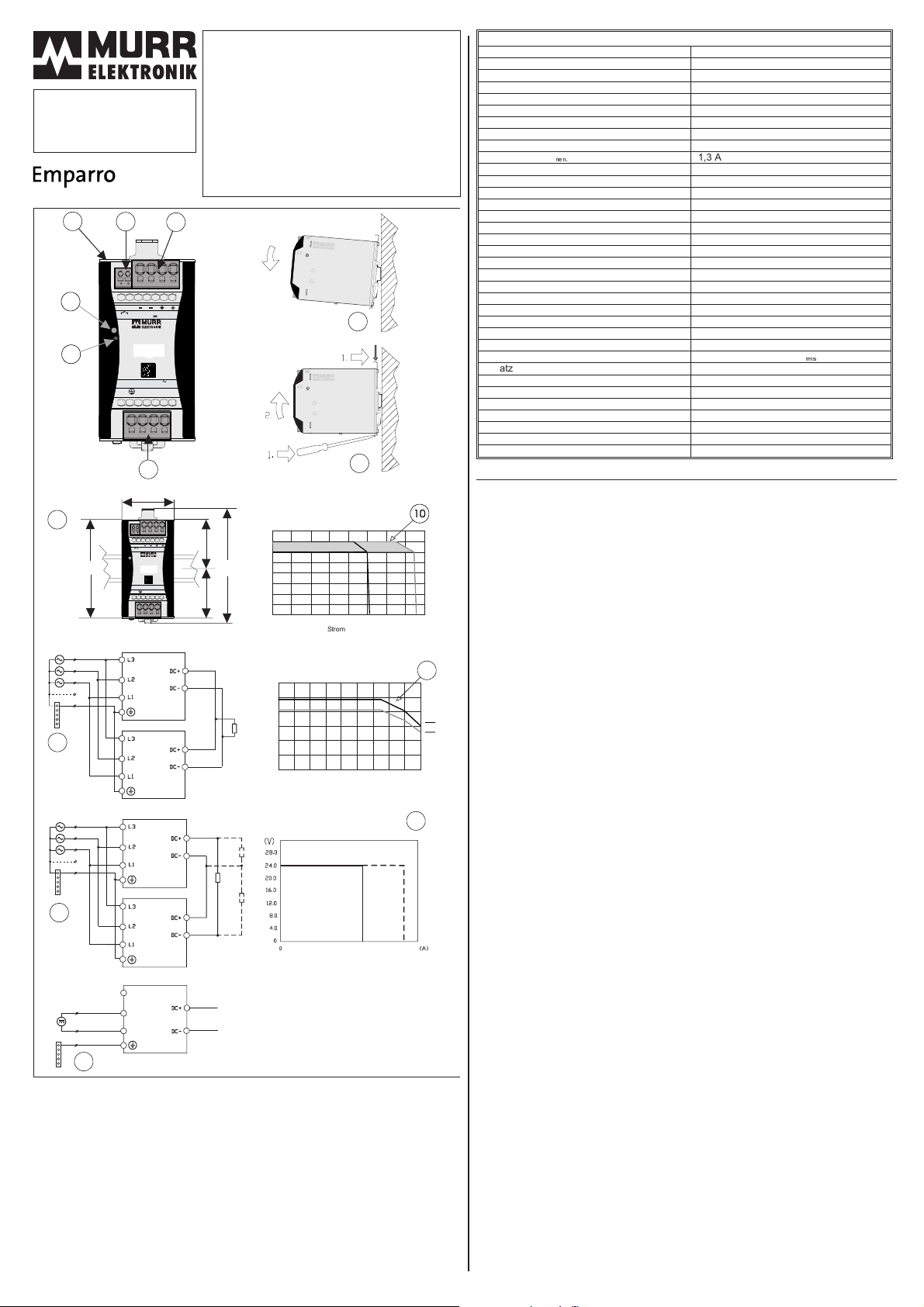
(5) Montaje [9]
La guía se ha de fijar de forma sólida de forma que no se flexione cuando se coloque o extraiga
la fuente. Instrucciones de montaje [7]. Instrucciones de extracción [8].
(6) Activación
La fuente viene ya viene lista de fábrica para ser usada. Mirar los esquemas de conexión para
montajes serie y paralelo. Revise el circuito de conexiones para tensiones continuas [15].
(7) Capacidad de carga
La corriente nominal es de 20 A pero debido a la naturaleza de las cargas en la industria, la
fuente ha sido diseñada para soportar cargas con altas corrientes de arranque sin dañar la
fuente y sin desconexión de ésta. La curva [10] muestra la típica característica voltaje /
corriente. La zona donde la curva cae es debido a la limitación de corriente. La curva [11]
muestra la característica típica de sobrecarga límite en función de la temperatura. Para
asegurar una correcta ventilación por convección, la fuente se ha de montar
perpendicularmente sobre la guía. Las fuentes de alimentación están diseñadas para dar el
150% de la potencia de salida durante un periodo de 5 segundos [12].
(8) Conexión en paralelo [13]
Pueden instalarse hasta un máximo de 3 unidades en paralelo. El voltaje en circuito abierto de
cada una de las fuentes se ha de fijar a un mismo valor. La exactitud con la que se fije,
determinará cómo de bien compartirán la corriente de carga. Gire el switch paralelo a la posición
ON. El tipo de cable y la longitud de éste entre las fuentes y el nodo común ha de ser el mismo.
(9) Conexión en serie
Un máximo de 2 unidades se pueden montar en serie para suministrar o bien 48 VDC o bien +/-
24 VDC. Ver el diagrama de conexionado [14].
(10) Activación de circuitos protectores a la salida de la fuente:
Para vigilancia de control en las salidas de las fuentes de alimentación de hasta 28 VDC
recomendamos “MICO”. Por ej.: MICO 4.10 Art. Nr. 9000-41034-0401000
Otras versiones: Bajo demanda o en Internet: www.murrelektronik.com
Para mayores salidas de tensión (conexión en serie) o uso de autómatas de seguridad estándar,
en caso de cortocircuito la fuente puede conectarse por ej. con magnetotérmicos ABB:
- S201-C3A
- S201-Z10A
Reservado el derecho de modificaciones
3 PHASE
®
Para aprovechar al máximo las
características de esta fuente de
alimentación y para asegurar una larga
fiabilidad a sus equipos, le aconsejamos lea
estas instrucciones con atención antes de la
instalación y su posterior uso. Estas habrían
de servir como referencia para futuras
consultas.
Emparro 20-3x360-500/24
Ref.: 85692
Instrucciones de montaje y uso
(2) Especificaciones técnicas, Ref. 85692 V1.7
Tensión de nominal (L-L) 3 x 360 - 500 VAC
Rango de tensión de entrada (L-L) 3 x 324 - 572 VAC
Tensión de nominal (L-N) 3 x 208 - 288 VAC
Rango de tensión de entrada (L-N) 3 x 187 - 330 VAC
Voltaje nominal funcionamiento entrada CC 500 - 700 VDC*
Rango de voltaje funcionamiento entrada CC 450 - 745 VDC*
Voltaje nominal funcionamiento 2 fases 2 x 380 - 500 VAC
Rango de voltaje funcionamiento 2 fases 2 x 340 - 572 VAC
Frecuencia nominal 50/60 Hz ±6%
Corriente de entrada, Inom 1,3 A / 3 x 360 VAC - 1,0 A / 3 x 500 VAC
Corriente nominal con funcionamiento 2 fases 2,1 A / 2 x 360 VAC
Corriente de arranque < 13 A / 3 x 500 VAC después 1 ms
Eficiencia (típica) 94,8% / 3 x 400 - 94,5% / 3 x 480 VAC
Factor de potencia (típico) 0,75 / 3 x 400 VAC - 24 VDC / 20 A
Fusible interno 3 x 6,3 A (T)
Fusible externo, máx. 3 x 32 A (T)
Clasedeprotección 1
Voltaje de salida, ajustable 24 - 28 VDC 24 VDC
Regulación en estática +/-1%
Regulación dinámica 0-> 100%, 5% 1ms / 100%-> 5%, 5% 1ms
Tiempo de arranque < 400 ms
Tiempo de retención de la salida (caída de red) >20ms/3x400VAC-24VDC/20A
Corriente de salida 24 VDC 20,0 A (+60°C) / 15,0 A (+70°C)
Corriente de salida 28 VDC 17,2 A (+60°C) / 12,8 A (+70°C)
Corriente de salida (power boost) 24 VDC 30 A / > 5 s
Corriente de salida, en cortocircuito, típica 24 A
Rizado de salida < 20 mV
rms
Uso como cargador de batería Si (con la función de modo paralelo en ON)
Sobrecarga / Protección de temperatura Sí
Desconexión por sobrevoltaje Max. 31 VDC
Humedad relativa 5 - 95% , sin condensación
Temperatura máximo del aire circundante -40°C - +60°C (derating 60°C-70°C)
Temperatura de almachen -40°C - +85°C
Tipo de protección, chasis, EN 60529 IP20
Dimensiones W x H x D; Peso 65 x 143 x 162 mm; 1,2 kg
* La operación DC no está incluida en la homologación UL. El cliente debe utilizar una protección
externa apropiada.
3x400 VAC
DC24V
13
PE
(DC+/-24V)
(DC +/ -24V)
DC48V
14
3x400 VAC
PE
500-700 VDC
PE
+
-
L1
L2
L3
15
(+)
(-)
Temperatura ambiente [°C]
Corriente de salida [A]
11
50% 100% 150%
12
0
5
10
15
20
25
30
-20-10 0 10203040506070
24 V
28 V
7
8
SWITCHMODE POWER S UPPLY
SWITCHMODE PO WER SUPPLY
ART.NO. 85692
ART. NO. 8569 2
INPUT:360 - 500VAC, 3W+PE, 50-60Hz 3x1.3A
Emparro20-3x360-500/24
OUTPUT:24 VDC, 20 A, SELV
OUTPUT: 24 VDC, 20 A, SELV
IP20,t -25 ... +60 C
o
IP20, t -25 ... +60 C
o
CAUTION
CAUTION
-Read instruction manual before installation and use.
-Re ad ins tructi on manu al be fore in stalla tion an d use.
-Risk of electric shock. Do not open the case.
-Risk ofelectricshock.Donotopenthecase.
-No user serviceable parts inside.
-No u ser s ervic eable p arts in side.
!
!
ATTENTION
ATTEN TI O N
-Reportez-vous aux instructions de service avant le
-Reportez-vousauxinstructionsdeserviceavantle
montageet la mise en service de l'appareil.
montage et la mise en s ervi ce de l' appar eil.
-Risque d'électrocution. Ne pas ouvrir l'appareil.
-Ri sque d' électr ocuti on. Ne p as ouvri r l'ap pareil .
-Ne contient pas de pièces interchangeables
-Ne conti ent pas de pièces in terchangeables
parl'utilisateur
parl'utilisateur
Madein Czech Republic
MadeinCzechRepublic
potenti al fee alarm cont ac t
potentialfeealarmcontact
(NO - contac t 13 / 14)
(NO - contac t 13 /14 )
60VD C, 50 m A, SELV
60 VDC , 50 m A, SELV
OFF- ON
OFF - ON
Parallelmode sw itch
Parallelmode switch
SWITCHMODE POWER S UPPLY
SWITCHMODEPOWERSUPPLY
ART.NO. 85692
ART
.NO.85692
INPUT:360 - 500VAC, 3W+PE, 50-60Hz 3x1.3A
INPUT
:360-500VAC,3W+PE,50-60Hz3x1.3A
Emparro20-3x360-500/24
OUTPUT:24 VDC, 20 A,SELV
OUTPUT
:24VDC,20A,SELV
IP20,t -25 ... +60 C
o
IP20,t-25...+60C
o
CAUTION
CAUTION
-Read instruction manual before installation and use.
-Readinstructionmanualbeforeinstallationanduse.
-Risk of electric shock. Do not open the case.
-Riskofelectricshock.Donotopenthecase.
-Nouserserviceable parts inside.
-Nouserserviceablepartsinside.
!
!
!
ATTENTION
ATTENTION
-Reportez-vous aux instructions de service avant le
-Reportez-vousauxinstructionsdeserviceavantle
montageet la mise en service de l'appareil.
montageetlamiseenservicedel'appareil.
-Risqued'électrocution.Ne pas ouvrir l'appareil.
-Risqued'électrocution.Nepasouvrirl'appareil.
-Ne contient pas de pièces interchangeables
-Necontientpasdepiècesinterchangeables
parl'utilisateur
parl'utilisateur
MadeinCzechRepublic
MadeinCzechRepublic
potenti al fee alarm cont ac t
potentialfeealarmcontact
(NO - contac t 13 / 14)
(NO-contact13/14)
60VD C, 50 m A, SELV
60VDC,50mA,SELV
OFF- ON
OFF-ON
Parallelmode sw itch
Parallelmodeswitch
continuos
corto plazo
Corriente [A], (t = 60°C)
Voltaje [V]
0
4
8
12
16
20
24
28
32
0481216
20 24 28 32
10
9
65
123123
123
61,5
61,5
143
OK / Alarm
OK / Al arm
Uout Adj. 24-28V
UoutAdj. 24-28V
Art. No. 85692
Art. No. 8569 2
13 14
13 14
L1
L1
L2
L2
L3
L3
INPUT Y 3x360-500VAC
50/60Hz
50/60Hz
1.3 - 1.0A
1.3 - 1.0A
OUTPUT:
OUTPUT:
Alarm
Alar m
24VDC / 20A
24VDC / 20A
Emparro
Emparro
1
2
3
56
4
OK / Alarm
OK / Alar m
Uout Adj. 24-28V
Uout Adj. 24-28V
Art. No. 85692
Ar t. N o. 8 56 92
13 14
13 14
L1
L1
L2
L2
L3
L3
INPUT Y 3x360-500V
INPUT Y 3x360-500V
50/60Hz
50/60Hz
1.3 - 1.0A
1.3 - 1.0A
OUTPUT:
OUTPU T:
Alarm
Alarm
24V / 20A
24V / 20A
Emparro

Murrelektronik GmbH
Falkenstraße 3, 71570 Oppenweiler, GERMANY
Phone +49(0)7191/47-0
(EN) Safety instructions and warnings
Read the installation notes and safety instructions first. For additional information please refer to the corresponding datasheet at www.murrelektronik.com
Warning! This device may only be installed by qualified personnel and in according to the relevant national regulations. The power supply unit is designed
and manufactured for installation in a control cabinet. Improper handling of this power supply can result in death, severe personal injury or significant
property damage. The control cabinet shall serve as an electrical and fire enclosure.
Caution! Look for visible damage at the housing or the connection terminals or loose parts in the unit.
- No external object may fall into the unit during the assembly, installation and operation
- Before working on the device disconnect system from supply network and protect against re-powering
- In case of damage, do not operate the device and return it to your dealer for exchange
Warning! Danger of electric shock.
Warning! Housing may be hot when operated.
Note: Dispose of the product at the end of its service life according to the applicable statutory regulations.
(DE) Sicherheitsvorschriften und Gefahrenhinweise
Zunächst die Einbauhinweise und die Sicherheitsvorschriften durchlesen. Zusätzliche Informationen enthält das Datenblatt auf www.murrelektronik.com.
Warnung! Das Gerät darf nur von Fachpersonal unter Befolgung der geltenden nationalen Bestimmungen eingebaut werden. Das Netzgerät ist für den
Einbau in einem Steuerschrank vorgesehen. Der unsachgemäße Gebrauch des Netzgeräts kann zu Unfällen mit Todesfolge oder schweren Verletzungen und
zu schweren Sachschäden führen. Der Schaltschrank muss als Elektrik- und Brandschutzgehäuse dienen.
Vorsicht! Gerät auf sichtbare Schäden an Gehäuse und Anschlüssen und auf lose Teile prüfen.
– Beim Zusammen- und Einbau und beim Betrieb dürfen keine Fremdkörper in das Gerät gelangen.
– Vor Arbeiten an dem Gerät das System von der Stromzufuhr trennen und gegen Wiederverbindung schützen.
– Bei Beschädigung das Gerät nicht verwenden und beim Händler umtauschen.
Warnung! Stromschlaggefahr.
Warnung! Gehäuse kann während des Betriebs heiß werden.
Hinweis: Das Gerät am Ende der Nutzungsdauer gemäß den geltenden Vorschriften entsorgen.
(FR) Consignes de sécurité et avertissements
Veuillez lire au préalable les notes d’installation et les consignes de sécurité. Pour plus d’informations, veuillez vous référer à la fiche technique correspondante sur le
site www.murrelektronik.com
Avertissement ! L’appareil peut uniquement être installé par un personnel qualifié et conformément aux réglementations nationales applicables. L’unité
d’alimentation électrique est conçue et fabriquée pour une installation dans une armoire électrique. Une mauvaise utilisation de cette alimentation
électrique peut entraîner la mort, des blessures graves ou des dommages matériels importants. L’armoire électrique doit faire office d’habillage électrique
ignifuge.
Attention ! Vérifiez l’absence de dommages visibles sur le boîtier et les bornes de connexion, ainsi que l’absence de pièces desserrées.
- Aucun objet externe ne doit tomber dans l’unité lors de l’assemblage, de l’installation et du fonctionnement.
- Avant de travailler sur l’appareil, déconnectez le système du réseau d’alimentation et protégez-le contre toute reconnexion.
- En cas de dommage, n’utilisez pas l’appareil, et retournez-le au vendeur pour un échange.
Avertissement ! Risque de décharge électrique.
Avertissement ! Le boîtier risque d’être chaud lors de son fonctionnement.
Remarque : à la fin de sa durée de vie, éliminez le produit conformément aux dispositions légales en vigueur.
(ES) Instrucciones y advertencias de seguridad
Antes de nada, lea las notas sobre la instalación y las instrucciones de seguridad. Para obtener más información, consulte la ficha técnica correspondiente en
www.murrelektronik.com
¡Advertencia! La instalación de este dispositivo solo la debe llevar a cabo el personal cualificado conforme a las normativas nacionales correspondientes. La
fuente de alimentación ha sido diseñada y fabricada para instalarse en un armario de mando. El manejo inadecuado de la fuente de alimentación puede
provocar la muerte, daños personales graves o daños materiales de importancia. El armario de mando servirá como dispositivo de protección eléctrica e
ignífuga.
¡Atención! Revise los daños visibles en la carcasa, los terminales de conexión o las piezas sueltas de la unidad.
- Procure que no penetre ningún objeto extraño en la unidad durante los procesos de montaje, instalación y manejo
- Antes de utilizar el dispositivo, desconecte el sistema de la red de abastecimiento y asegúrese de que no se vuelva a encender
- En caso de daños, no utilice el dispositivo. Devuélvaselo a su distribuidor para que se lo cambie por otro
¡Advertencia! Riesgo de descarga eléctrica.
¡Advertencia! Es posible que la carcasa esté caliente durante el funcionamiento.
Nota: Deseche el producto al final de su vida útil conforme a lo establecido en la normativa legal vigente.
Rev. B

(EN) Murrelektronik reserves the right to make technical changes to this manual without prior notice.
(DE) Murrelektronik behält sich das Recht vor, ohne vorherige Ankündigung technische Änderungen an diesem Handbuch vorzunehmen.
(IT) Istruzioni e avvisi di sicurezza
Leggere per prima cosa le note sull’installazione e le istruzioni di sicurezza. Per ulteriori informazioni, consultare la scheda tecnica corrispondente all’indirizzo
www.murrelektronik.com
Avvertenza! Questo dispositivo può essere installato esclusivamente da personale qualificato e nel rispetto delle normative nazionali pertinenti.
L’alimentatore è progettato e fabbricato per essere installato in un armadio di controllo. Una manipolazione errata di questo alimentatore potrebbe causare
morte, lesioni personali gravi o danni significativi alle proprietà. L’armadio di comando funge da armadio elettrico e antincendio.
Attenzione! Verificare che la custodia esterna e i terminali di collegamento non siano visibilmente danneggiati e che l’unità non presenti parti allentate.
- Assicurarsi che nessun oggetto esterno cada nell’unità durante l’assemblaggio, l’installazione e l’uso.
- Prima di effettuare operazioni sul dispositivo, scollegare il sistema dalla rete elettrica e proteggerlo da alimentazione di ritorno.
- Se il dispositivo è danneggiato, restituirlo al fornitore e chiedere la sostituzione.
Avvertenza! Pericolo di scossa elettrica.
Avvertenza! Durante l’uso, la custodia esterna potrebbe essere calda.
Nota: al termine della vita utile del prodotto, questo deve essere smaltito secondo quanto previsto dalle norme in vigore.
(CN)
安全
说
明与
警告
请先阅读安装注意事项和安全说明。其他信息,请参⻅对应的数据表:www.murrelektronik.com
警告!本设备只能由有资质的人员根据相关国家法规进行安装。电源装置专⻔针对在控制柜中进行安装而设计和制造。错误处理
此电源可能会导致死亡、重伤或造成重大财产损失。控制柜应作为电气和防火外壳。
注意!检查外壳或连接端口上是否有可⻅的损坏,或者装置中是否有松动的零件。
- 组装、安装和操作期间,不得让异物落入装置中。
- 在使用设备之前,请将系统与电源断开并防止意外通电
- 如有损坏,请停止使用设备并将其退回经销商以便进行更换
警告!有触电⻛险。
警告!使用期间外壳可能会发热。
注意:请在产品使用寿命结束后按照适用法律法规进行处置。
(RU) Указания по технике безопасности
Прежде всего прочитайте примечания по установке и указания по технике безопасности. Дополнительные сведения см. в соответствующем паспорте
изделия по адресу www.murrelektronik.com
Внимание! Производить установку этого устройства разрешается только квалифицированному персоналу с соблюдением соответствующих
национальных регламентов. Этот блок питания разработан и изготовлен для установки в шкафу управления. Ненадлежащее обращение с этим
блоком питания может привести к смерти, тяжелой травме или значительной порче имущества. Шкаф управления должен обеспечивать функции
электрического и противопожарного кожуха.
Осторожно! Осмотрите кожух, соединительные разъемы и отдельные компоненты блока на предмет видимых повреждений.
- Не допускайте падения посторонних предметов в блок во время его сборки, установки и эксплуатации.
- Перед работой с устройством отсоедините систему от сети питания и защитите ее от повторной подачи питания.
- В случае повреждения не приступайте к эксплуатации устройства и верните его дилеру для замены.
Внимание! Опасность поражения электрическим током.
Внимание! Во время эксплуатации кожух может сильно нагреваться.
Примечание. По истечении срока службы изделия утилизируйте его согласно применимым нормативным правилам.
(PT) Instruções de segurança e avisos
Leia primeiramente as notas de instalação e instruções de segurança. Para mais informações, consulte a respetiva ficha técnica em www.murrelektronik.com
Aviso! Este dispositivo só deverá ser instalado por pessoal qualificado e de acordo com os regulamentos nacionais aplicáveis. A fonte de alimentação foi
concebida e fabricada para instalação num armário de controlo. O manuseamento incorreto desta fonte de alimentação pode resultar em morte, danos
físicos graves ou prejuízos materiais significativos. O armário de controlo deve servir como corta fogo e caixa elétrica.
Atenção! Verifique a existência de danos visíveis na estrutura ou nos terminais de ligação ou peças soltas na unidade.
- Não podem cair quaisquer objetos externos dentro da unidade durante a montagem, instalação e funcionamento
- Antes de trabalhar no dispositivo, desligue o sistema da rede de fornecimento elétrico e proteja-se contra um retorno da energia
- Caso o dispositivo seja danificado, não o utilize e devolva-o ao seu fornecedor para troca
Aviso! Risco de choque elétrico
Aviso! A estrutura do dispositivo poderá ficar quente quando em funcionamento
Nota: Elimine o produto no fim da sua vida útil de acordo com a legislação em vigor.
This manual suits for next models
1
Table of contents
Languages:
Other Murrelektronik Power Supply manuals
Popular Power Supply manuals by other brands

OCZ
OCZ STEALTHXSTREAM 400 - MECHANICAL DRAWING manual

DuraWatt
DuraWatt DS12VD user manual

GW Instek
GW Instek PRP Series Programming manual

GHM
GHM GREISINGER GNG 10 operating manual

Tektronix
Tektronix PS 503S instruction manual

TDK-Lambda
TDK-Lambda LZS-A1500-3-001 Installation, operation and maintenance manual

Schumacher
Schumacher SBP1 owner's manual

Allen-Bradley
Allen-Bradley Bulletin 1609 user manual

THORLABS
THORLABS GPS011-EC Original instructions

Agilent Technologies
Agilent Technologies 87421A Product overview

Delta Electronics
Delta Electronics Delphi IPM24S0B0 Specification sheet

EVGA
EVGA 500B user manual