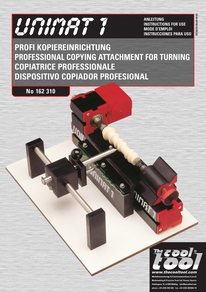
Shopsmith Lathe Duplicator User manual

Lathe
Duplicator
555209
\
\

Introduction Safety
Your
Shopsmith
Lathe
Duplicator
accessory provides a simple and ac-
curate way to produce duplicate spin-
dles and bowls, making possible a
new and precise method
of
lathe turn-
ing. The
duplicator
components are
designed
to
mount on the Shopsmith
Mark V Models
500
and
510
as well
as on Mark
II
and Mark VII systems.
NOTE
• Ifyou received your Mark V prior
to November 1985, you own a
Model 500.
• If you received your Mark V after
November 1985, you own either
a Model
500
or Model
510.
Check
the vent plate, located around
the
auxiliary
spindle,
for
the
Model Number
of
your Mark
V.
Rather than using conventional
lathe chisels, the Lathe Duplicator
features a tool rest assembly which
slides on a smooth table. You're in
complete control of the tool rest as-
sembly as you grasp its
two
handles
and guide
its
follower
along a tem-
plate and
it..?
carbide
cutter
into
your
workpiece. The carbide
cutter
has
an
extremely tong cutting life
without
sharpening.
A durable channel assembly provides
an
adjustable mounting track for
two
template support assemblies and a
guard assembly. With the template
centerline located directly over the
workpiece centerline, the tool rest as-
sembly is free
to
be moved around the
table,
following
the
template
and
producing an exact duplicate. The ad-
vantages
of
this configuration include
the
ability
to turn bowls as well as
spindles and
to
produce true under-
cuts
. When
duplicating
spindles, use
either a flat template or
an
existing
spindle. For bowl turning,
only
a
flat
template can
be
used. If you wish,
you can work
without
a
template
to
develop skill.s in freehand turning.
As you operate the Lathe Duplicator,
you
must
be
responsible for knowing
your own
limitations
as
well as those
of
the
duplicator
.
To
avoid serious
injury,
constantly
remind
yourself
to
use the accessory correctly together
with the proper safety equipment.
We
wish you the best in all your
woodworking endeavors.
We
know that
your Shopsmith Lathe Duplicator will
become
an
indispensable accessory in
your workshop.
We
know that you'
re
eager
to
get
started using your Lathe Duplicator,
but please take time to read this man-
ual before you begin. Then keep it
handy for future reference.
Table of Contents
Safety
..................
.
....
.
..
2
General Information
.......
..
.....
5
Assembly and Setup
...
..........
6
Alignment
and
Adjustment
...
.
...
.
11
Templates
......
...
.....
.
..
.
....
13
Operations .
.....
...
. .
..
....
. .
...
15
Maintenance
...........
......
...
26
Troubleshooting
............
..
. . .
27
Parts List
..............
. .
....
...
28
Quick Reference Index
.......
.
..
. .
31
The Shopsmith Lathe Duplicator has
many built-in safety features. But the
effectiveness of these features
de-
pends on you. Power tool safety is no
more than good common sense.
To
protect
yourself from injury:
• READ, UNDERSTAND AND FOLLOW
ALL the
information
in
this
Owners
Manual WHENEVER you operate, set
up, align, adjust, repair and maintain
the
lathe
Duplicator.
• Also, READ, UNDERSTAND AND
FOllOW
ALL the information in the
Owners Manual
for
the Mark V on
which
the Lathe
Duplicator
will
be
mounted.
Throughout this manual, we
list
WARNINGS, CAUTIONS, and NOTES.
We
advise that when you come
to
one
of
these listings, please read and
understand it fully. Their meanings
are:
WARNING
A WARNING is given when failure
to
follow
the directions could
reo
suit
in injury,
loss
of
limb, or life.
A CAUTION is given when failure
.to
follow
the
directions
cou~d
r')·
suit
in temporary
or
permanent
damage
to
the equipment.
NOTE
A NOTE is used
to
highlight an im-
portant
procedure,
practice
or
condition.
Eye Protection
Always wear eye protection when you
use power tools. Use goggles, safety
glasses or a face shield to protect
your eyes.
• Goggles completely surround and
protect your eyes. Many goggles will
also
fit
over regular glasses.
Be
sure your goggles
fit
closely, but
comfortably.
2

WARNING Safety
• Safety glasses
don't
fog as easily
as
goggles and can
be
worn all the
time. Regular glasses normally have
only impact resistant lenses. They
are not safety glasses.
• A face shield protects your entire
face, not
just
your eyes. And you can
flip it up out
of
the way when you
don't
need it. A face shield can
be
used with regular glasses.
Ear Protection
Prolonged exposure
to
high intensity
noise from high speed power tools
can damage your hearing.
• Hearing protectors screen out noise
levels that can damage ears. Wear
hearing protectors when you're ex-
posed
to
high intensity power tool
noise for prolonged periods
of
time.
Sawdust and Chips
Sawdust and chips can
be
fire hazards
and breathing sawdust can
be
a health
hazard. Sawdust may cause you phys-
ical discomfort, especially
if
you have
emphysema, asthma, or
an
allergic
reaction. The sawdust from some
woods can also
be
toxic.
• Wear a close-fitting
dust
mask if a
significant
amount
of
dust is
re-
leased into the air. Clean or replace
the filters in the mask regularly.
• Open a window or use a fan
to
venti-
late your shop.
Guarding for Turning
Most shop accidents happen to wood-
workers who believe they are
too
experienced to use the guards and
safety devices. Although proper use
of
guards and safety devices usually
requires a small amount
of
additional
setup, the security
that
you and your
family obtain from them is well worth
the effort. Don't take shortcuts. It
doesn't pay.
• Keep the guard in place during
duplicator
operations. Also use the
guard when doing conventional
lathe turning on the Mark
V.
Dress
Loose hair and
clothing
which could
be
entangled
in
rotating workpieces
are very hazardous.
• Tuck long hair under a hat or tie it
up.
Do
not wear ties, gloves, loose
clothing
or
jewelry. Roll sleeves up
above your etbows.
General Safety Rules
for Power Tools
• Know your power tool. Read the
owners manual carefully. Learn
its
application and
limitations
as well as
the specific potential hazards pecul-
iar to the tool.
• Ground all tools (unless double
insulated). If tool is equipped with an
approved 3-conductor cord and a
3-prong grounding type plug to fit the
proper grounding type receptacle,
the green conductor in the cord is
the grounding wire. Never connect
the green wire to a live terminal.
• Wear proper eye and ear protec-
tion_
Also, wear a dust mask.
• Keep guards in
place.
Always
keep guards
in
working order and in
proper alignment and adjustment.
Most injuries
occur
on unguarded
power tools.
• Remove
adjusting
keys and
wrenches. Form habit
of
checking to
see
that
keys
and
adjusting
wrenches are removed from tool
be-
fore turning it on.
• Wear proper apparel.
Do
not wear
loose clothing, ties, gloves, or jew-
elry. Roll sleeves up above your el-
bows, wear nonslip footwear, and
tucUong
hair under a hat.
•
Do
not operate power tools if
you
are fatigued, taking medication, or
under the influence of alcohol or
drugs.
•
Avoid
dangerous environments.
Don't use power tools in damp, wet
or
explosive atmospheres.
• Keep work areas well lit, clean,
and free from clutter.
•
Do
not force the tool. It will do the
job
better and safer at the rate for
which it was designed.
• Use the right tool. Don't force a
tool or accessory
to
do a
job
for
which it was not designed.
• Direction of feed. Feed the work-
piece into the
cutter
against the
ro-
tation
of
the
cutter
ONLY.
• Check damaged parts. A dam-
aged guard
or
part should
be
prop-
erly
repaired
or
replaced
before
further use. If a strange noise or vi-
bration develops, immediately turn
off
the power, unplug the machine
and correct the problem.
• Secure workpieces. Use clamps,
fixtures, and other devices
to
hold
workpieces when practical. It's safer
than using your hands and it frees
your hands
to
operate the tool.
•
Do
not overreach. Keep proper
footing and balance at all times.
•
Turn
off the tool and wait until it
comes to a complete stop before
re-
moving workpieces and scraps.
•
Do
not try to stop the tool
by
grab-
bing the workpiece or any part
of
the
tool. Turn
off
the tool and let it come
to
a complete stop by itself.
•
Do
not leave tool running unat-
tended. Turn power off. Don't leave
tool until it comes to a complete
stop.
• Avoid
unintentional
starting.
Make sure the switch is
in
the
"off"
position before plugging in or
un-
plugging the tool.
• Disconnect tools. T'I'rn
off
and un-
plug tools before changing acces-
sories
and
setups,
making
ad-
justments, and performing mainte-
nance and repair.
•
Do
not stand or lean
on
the tool.
You
could fall onto the tool or it could
tip over injuring you and/ordamaging
the tool.
• Maintain tools. Keep parts and
tools
sharp, clean and maintained
according to the Owners Manual.
• Make workshop childproof. Use
padlocks, masterswitchesor remove
starter keys.
• Keep children away. All visitors
should stay a safe distance from
power tools, and wear eye and ear
protection.
• Use recommended accessories.
Consult the owners manual for rec-
ommended accessories.
3

r
WARNING
Safety
Safety Rules for the Shopsmith Lathe Duplicator
•
Keep
your
hands,
fingers
and
other
parts
of
your body 2" away
from the rotating workpiece
until
it
is rounded.
After
it
is rounded use
caution when you
get
close
to
the
rotating workpiece.
Do
not
touch
the
workpiece as
it
turns.
• Keep the guard in place when·
ever you're performing turning oper·
ations. Position
it
not
more than 1/2"
from the workpiece.
•
When
turning
glued·up
stock,
make sure glue
joints
are strong.
Glue the
stock
and leave
it
clamped
for at least
24
hours prior
to
turning.
• Wear proper apparel. Never wear
jewelry, gloves, ties, loose
clothing
or
clothing
with
long sleeves. Keep
long hairtucked underahat. Jewelry,
gloves, ties,
clothing
and hair could
become entangled in the workpiece.
• Do
not
exceed
recommended
speeds.
Use
the lowestspeed setting
when
starting
to
turn
a
new
workpiece.
• When mounting
stock
between
the centers, the spurs
of
the drive
center
and the cup
of
the
tailstock
center
must
penetrate
at
least 1/16"
into
the stock.
Do
not
use a drive
center
or
tailstock
center
if
the point
is
damaged.
The
stock
could
be
thrown from the lathe.
• Wax or soap the end
of
the
stock
that
mounts to the
cup
center. This
lubrication
helps keep the center
from wearing
into
the
stock
and
causing the
stock
to
loosen on the
lathe. The ball bearing live center is
highly recommended
for
use
with
the
Lathe Duplicator.
• When
mounting
stock
to
a face·
plate, use
#12
x 1·1/4" long screws.
The screws
must
penetrate at least
1"
into
the stock. The surface
of
the
workpiece
that's
against the face·
plate
must
be smooth and true.
• Cut faceplate
stock
round and
spindle
stock
that's
more than 3"
square
into
an
octagon.
This
reo
moves excess stock, minimizes im·
balance,
reduces
vibration
and
makes turning large diameter
stock
safer and easier.
• Check the balance
of
the work·
piece. Prior
to
mounting
workpieces
more than 3" in diameter, check and
adjust
the center
of
balance (dy·
namic
center).
Unbalanced
work·
pieces could be thrown from the
lathe.
• Do
not
turn on the power
with
the
cutter
or
any part
of
the
tool
rest as·
sembly against the workpiece. Turn
on the machine and
let
it
come up
to
speed before starting the cut.
• Do
not
stand in the path
of
rota·
tion
of
the workpiece when you
first
turn on the machine. If the machine
is set on the wrong speed
or
the
workpiece is unbalanced or improp·
erly mounted, the workpiece could
be thrown from the lathe.
• Feed the
cutter
slowly
into
the
workpiece. Use both hands
to
hold
onto
and
control
the
tool
rest
assembly.
• Periodically, turn
off
the machine
and check
that
the workpiece is held
securely between the centers or on
the faceplate.
• Do not lean across
or
reach un·
derneath the lathe while
it
is running.
•
Do
not try
to
stop
the lathe by
grabbing the
stock
or
any part
of
the
machine. Turn
off
the power and,let
the lathe come
to
a complete stop
by itself.
•
Do
not
part the
stock
completely
or
turn the spindle down
to
such a
small diameter
that
it
snaps on the
lathe.
This
can
be
extremely
dangerous.
• Do
not
turn
stock
with
splits,
loose knots, or
other
defects
that
could
cause
the
stock
to
break,
splinter
or
come loose while turning.
Never turn second·hand lumber. If
you
hit
a nail
or
screw, you could
be
hit
by pieces
of
metal.
•
Remove
the
Lathe
Duplicator
from the Mark V before sanding or
finishing a workpiece on the lathe.
• Use
only
recommended
Shopsmith parts and accessories on
your Lathe Duplicator. NEVER use
non·Shopsmith replacement parts or
accessories. They are not designed
like
Shopsmith
parts.
Using
no
,
n.:-
Shopsmith parts may create a
r.
.az.
ardous
condition
and
will
void-'
jour
warranty.
•
Do
not
grind thecutters. The dust
created by grinding the carbide can
cause eye and skin
irritation
as well
as respiratory system and internal
organ damage. Replace worn cutters
with
new.
• Do
not
allow
the
cutter
to
come
in
contact
with
the parts
of
the Lathe
Duplicator
or
Mark
V.
The
cutter
will
cause damage
to
the parts and you
could
be
hit
by pieces
of
metal.
4

General
Information
Getting to Know Your
Shopsmith Lathe
Duplicator
Your Shopsmith Lathe Duplicator is a
versatile accessory. Become familiar
with all
of
its
parts and
functions
before you begin to use it.
Nomenclature
The functioning parts
of
the Lathe
Duplicator are:
1.
Channel-Holds
the
template
support assemblies and the guard
assembly.
2.
Template
Support
Assemblies-
Support eithera
flat
templateor
an
orig-
inal spindle.
3.
Guard
Assembly-Serves
as both
a guard and a
chip
deflector.
4.
Support
Brackets-Clamp
to
the
way tubes to support the channel.
5.
Tool Rest
Assembly-Contains
the
carbide
cutter
and follower. It slides
on the table surface and is
controlled
by handles on each side
of
its heavy
aluminum base.
6.
Follower-Follows
the template
or
spindle to
be
duplicated. Must
be
the same shape as the carbide cutter.
7.
Follower
Support-Supports
the
plastic follower and mounts to the fol-
lower upright.
8.
Follower Adjusting
Knob-Permits
the
follower
support
to
be raised
and lowered on the
follower
upright.
9.
Follower
Upright-Permits
the fol-
lower support to
be
adjusted vertically.
10.
Cutter Adjusting
Knob-Permits
the
cutter
support to
be
positioned a
controlled amount
in
or out for align-
ment with the follower.
11. Carbide
Cutter-Cuts
the work-
piece. Made
of
solid carbide, it has
an
extremely long life when
cutting
wood.
It attaches
to
the
cutter
support.
12. Cutter
Guide-Aligns
the carbide
cutter
and also prevents
its
rotation
during cutting.
13.
Cutter
Support-Supports
the
carbide
cutter
and the plastic
cutter
guide. Adjusts in or
out
of
the topl
rest.
14.
Handles-Provide
a positive grip
that
make it easy
to
guide the tool
rest assembly.
15.
Table
Assembly-Provides
a
smooth surface for the tool rest
assembly.
16. Table
Posts-Permit
the table
assembly to
be
adjusted vertically in
the carriage.
17.
Spacer-Attaches
to the live center
enabling you to turn the full length
of
workpieces and
to
turn short
spindles.
18. Tailstock Live Center
(Optional)-
Not included with the Lathe Duplica-
tor. However it is recommended
be-
cause it provides a frictionless center
for spindle turning. Mounted in the
tailstock, it replaces the cup center. A
spacer supplied with the Lathe Dupli-
cator
increases the live center's length
for turning the full length
of
work-
pieces and also for turning short
spindles.
Specifications
The
specifications
of
the Lathe Dupli-
cator
will give you an idea
of
its
capabiIities:
Capacities
• Maximum spindle length
-34" with cup center
-33-1/2" with live center and no
spacer
- 32" with live center and
1-112"
long spacer
• Minimum spindle length
-6-1/4" with cup center
-5-3/4" with live center and no
spacer
-4-1/4" with live center and one
spacer
-2-3/4" with live center and two
spacers
• Maximum spindle
diameter-S"
with
a flat template, 4" with
an
original
spindle
• Maximum bowl
diameter-S"
with a
flat template
•
Maximum
depth
of
cut-2-1/4/1
(3-1/4/1
for
light
freehand
cuts
inside
bowls)
• Maximum template
length-36/1
• Maximum template
thickness-3/S"
•
Minimum
template
thickness-1/4"
(smaller templates only)
Weight-36.5
lb.
Height-47"
(when
mounted
on
Mark
V)
5

Assem
bl
y and
Setup
Assembly and Setup
NOTE
• Throughout the instructions,
ref-
erence numbers appear in paren-
theses following the part name.
These numbers correspond with
reference numbers on the draw-
ings
in
this section and the Parts
List section.
• The assembly and setup instruc-
tions for the "Table and Table
Support Assembly" are written
primarily for Mark V Models
500
and
510.
If your system is a Mark
II,
follow the instructions speci-
fied for Model
500;
for a Mark
VII,
follow the instructions specified
for Model
500
for mounting the
table supports and Model
510
for
mounting the table posts.
Before any operations can
be
per-
formed, you must assemble some
parts, set them up properly, and align
them on the Mark
V.
Your safety and
proper use of the Lathe Duplicator de-
pend on your following the Assembly
and Setup instructions exactly, espe-
cially those pertaining to your
specific
Mark V Model. If you're unsure as
to which Model Mark V you own, refer
to the NOTE on page
2.
Tools Supplied: 1/4",5/16" and 7/64"
Allen wrenches.
Tools and Supplies Required: 5/32"
standard Mark V Allen wrench, 9/16"
socket and socket wrench (or 9/16"
wrench), accurate combination square,
straightedge, mineral spiritsand
flooror
furniture paste wax.
Mark V Setup
Set up the Mark V
in
the lathe mode
according
to
the following procedures:
WARNING
Turn off and unplug the Mark V
before
you
begin
any
setup
procedures.
The following procedures assume
that the worktable has been
re-
moved,
that
there
is
nothing
mounted
on
any spindles of the
machine and that all alignment
and adjustment procedures spec-
ified
in
the Mark V Owners Manual
have been completed_
1_
Attach the three new labels to the
headstock. Remove the three labels
from the headstock and attach the
three new labels at the positions
shown. (See Figure
1.)
2.
Mount the drive center
on
the main
spindle. Slide
the
drive center all
the way onto the spindle. With the
5/32" Allen wrench, tighten the set-
screw in the base
of
the center so
that
the screw rests
firmly
against the
flat
of
the spindle.
3_
Mount the tailstock and tailstock
center_ Mount the
tailstock
in the base
mount
and
tighten
the
accessory
mount lock. Then insert the lathe cup
center or live center assembly in the
tailstock, so
that
it points toward the
headstock.
WARNING
• If you're using the cup center,
lubricate it with paste wax to
keep it from burning and wear-
ing into the wood causing the
workpiece
to
loosen
on
the
lathe_
• Do
not
use
more
than
two
spacers
with
the
live
center
assembly_
NOTE
• The
live
center
assembly
is
strongly recommended for use
as the
tailstock
center. The ball
bearing construction allows it
to
rotate with the workpiece.
Thus it
won't
burn into the wood
and
cause
loosening
of
the
workpiece as may sometimes
happen with the stationary cup
center.
• A spacer is supplied with your
Lathe Duplicator
to
extend the
length
of
the live center assem-
bly for turning the full length
of
the
workpieces
and
turning
short spindles.
(See
Figure
2.)
If
the live center assembly is dif-
ficult
to separate, hold the
re-
duced diameter end
of
the shaft
in avise and grasp the head with
adjustable jaw pliers.
Pad
the
jaws
of
both the vise and pliers
to
avoid marring the live center.
When
you
get ready to break down
the lathe mode, you'll probably
find the tailstock center
is
stuck
in
the tailstock because of the
pressure needed to keep the tail-
stock
workpiece
securely
be-
tween the centers_ If this is the
case, remove the tailstock from
the machine_ Lay the tailstock
over the edge of a workbench so
the eccentric mount
is
supported
by the table and the center is
hanging
free_
Tap the back side of
the center with a nylon or rawhide
mallet to pop it
loose_
Hold the
center with your free hand so the
center does not fall to the
floor_
DON'T hit the center with a metal
hammer!
£....,.~~'f.--;;-
LABELS
Figure
1.
Attach
the three new labels
to
the
headstock.
6

--
Assembly
and
Setup
4.
Align the lathe centers.
(See
Figure
3.)
Align the drive
center
and the
tailstock
center. (Refer
to
the Mark V
Owners ManuaL)
Both the drive center and the tail·
stock center must
be
directly
in
line with each other
in
order to
properly support a workpiece
so
that it can
be
turned.
SPACER
~6~
D
~
LIVE CENTER
Figure
2.
The spacer extends the length
of
the live center assembly.
DRIVE
Figure
3.
Both the drive center and tailstock
center must
be
directly
in
line with each
other
in
order to properly support a
workpiece.
Tool Rest Assembly
Assemble the tool rest assembly ac-
cording
to
the
following
procedures:
1.
Attach handles. Screw handles (52)
securely onto studs
of
tool
rest
base
(37).
2.
Install the cutter support. Insert the
cylindrical end of the
cutter
support
(58) into the tool rest base
(37)
until the
position indicating groove is flush
with the face
of
the base. Rotate the
cutter
support until the cutter·mount-
ing flat of the
cutter
support is paral-
lel
with
the base.
Use
the 5/32" Allen
wrench
to
tighten the
cutter
position-
ing setscrew
(42)
until it firmly
engages the V-groove of the
cutter
support, then back
off
1/4 turn.
NOTE
Seating the cutter positioning set·
screw in its groove in the
cutter
support will cause the position in·
dicating
groove to move
slightly
inward or outward from the face
of the tool rest base. Loosening
the setscrew 1/4 turn will allow ro-
tation
of
the cutter support and
approximately 1/16" in and out
movement.
3. Install the cutter adjusting knob.
Screw the
cutter
adjusting
knob
(51)
into the base (37) until the end
of
its screw
contacts
the back
of
the cut-
ter support (58).
4.
Install the follower upright. With its
flat
at
the
top, and facing toward
the back of the base, insert the follower
upright
(50)
into the top hole
of
the
base (37)
until
it
contacts
the
cutter
support (58). Use the 5/32" Allen wrench
to
tighten the setscrew (41)
lightly
against the follower upright.
5.
Install the follower adjusting knob
and the follower support. Install the
setscrew
(45)
into the knob
(44)
with the
cup point
facing
out-of the knob.
Thread the knob with setscrew
'"
installed into the follower support (46).
Slide the follower support over the
flat
of
the follower upright
(50)
and
tighten the knob.
NOTE
Wiggle the follower support as
you tighten the knob to properly
seat the cup point
of
the screw
against the flat of the follower up·
right. When properly assembled,
the setscrew will remain in the
knob when knob is loosened
to
adjust the follower.
.6. Install the carbide cutter and cutter
guide. Attach the triangle carbide
cutter (57), with the bevel down,
to
the
cutter support (58)
with
screw (56)
finger tight. Any
of
the
cutter's
three
points or flats may
be
positioned as
shown in Figure
4.
With the open
slot end of the cutter guide (55) pressed
firmly against a flat side
of
the car·
bide cutter, use the 7/64" Allen wrench
to
attach the cutter guide securely
to
the cutter support
with
screw (53)
and washer
(54).
Then, securely tighten
the screw (56) of the carbide cutter.
NOTE
Carbide
cutters
come
in
four
shapes for a variety of purposes:
•
Triangle:
Universal
cutter-
rough shaping through medium
detailing
.
(Included
with
the
Lathe Duplicator.)
• Round: Initial sh,:.ping, graceful
curves, cove cut>, dishing.
• Diamond: Fine beads, deep in-
tricate details, V-grooves, sharp
corners.
•
Square
:
Square
corners,
grooves,
straight
cylinders,
short dowels and plugs.
TRIANGLE
(2
POSITIONS)
I
c(@)
Gf:®>
DIAMOND
I<®p
C@
I
(@p~
ROUND SQUARE
Figure 4. Mounting positions
of
carbide
cutters and cutter guides.
7

Assembly and
Setup
7.
Install the follower. Remove the
triangle follower
(49)
from the plastic
molding strip. Attach
it
to the follower
support
(46)
with
a screw
(47)
and
washer
(48).
NOTE
• The profile
of
the follower
must
match the profile
of
the cutter.
• SAVE the three extra followers.
You'll need them
if
you purchase
the round, square and diamond
cutters.
Table and Table
Support Assembly
Assemble and set up the table and
table support assembly according to
the following procedures:
NOTE
In
the inverted position, the out-
feed end ofthe table assembly can
be
identified by the two screw
holes
·which
are closest to the
edge.
1.
Attach the table supports to the f
table assembly.
(See
Figure 5 for Model
500,
Figure 6 for Model
510.)
With the
outfeed end
of
the table assembly
(32)
positioned as shown, attach the
two
table supports
(34)
to the table assem-
bly with the four bolts
(33)
and washers
(33A)
positioned exactly
as
illustrated.
Finger tighten the bolts just enough to
allow the table supports
to
be
moved.
NOTE
When
positioned
correctly,
the
distance between post hole cen-
ters
of
the table supports should
be 12" for Model
500,
15-1/2"
for
Model
510.
BOLTS OUTFEED
END
Figure
5.
Table and table support assembly
for Model
500.
/
OUTFEED
END BOLTS
Figure
6.
Table and table support assembly
for Model
510
.
2.
Install and align the table posts.
(See Figure 5 for Model
500,
Figure 6
for Model 510.) Insert both table posts
(35)
intothe table supports
(34),
with the
rack teeth
of
the posts positioned as
shown. Make sure
th.e
posts bottom out
in the table supports. Align the
flats
of
the table posts with a straightedge,
then use the 5/32" Allen wrench to
tighten setscrews
(36)
securely.
3.
Clean and wax the table posts.
Clean the table posts
(35)
with
mineral
spirits. Then, sparingly apply floor
or
furniture
paste
wax
on the posts,
and rub it out thoroughly. Use a tooth-
brush or other
stiff
brush to remove
any wax residue from the rack teeth
of
the posts.
Use paste
floor
wax
or
paste fur·
niture wax.
Do
not
use
car
wax
or
spray furniture polish. The table
posts
need wax
for
both protec·
tion
and lubricatIon. Car wax of·
fers good protection
for
metal, but
it's
extremely hard and has
little
value as a lubricant. Furniture pol·
ish
isn't
hard enough. Paste
floor
wax
or
paste furniture wax pro·
tects
and lubricates.
4.
Install
the
table
assembly in the
carriage. Place the table posts
in
the
carriage mounting holes so that the
racks face toward the headstock
(Model 500) or away from the head-
stock
(Model 510). Then gently rock the
table back and forth until you feel
it
settle in place and the pinions engage
the racks. Raise and lower the table
once to be sure the table raising
mechanism operates smoothly. Lock
the table height
lock
with the table
near the top
of
travel.
DO
NOT force the .table up
or
down
if
the table raising
"1Tl-3-;ha·
nlsm binds. Carefully
lift
the table
out
of
the carriage and inspectthe
racks and pinions
for
damage,
dirt,
or
foreign
materials.
Also
check
that
the table posts are in·
serted completely
into
the table
supports. Correct any problem be·
fore you
attempt
to
remount the
table.
5.
Tighten the table supports. With
the carriage locked in place, use a
9/16" wrench to tighten the four table
support
mounting
bolts
(33). (See
Figure
7.)
8

Channel and Support
Bracket Assembly
rr
20 "
/'29
:Ji)
,
.';1TJ
//
-'l/
0!
25
;27
~
I
'
,
~28
2324
'0-
14
Assembly
and
,
Setup
Figure
7,
Tighten the
four
table support
mounting bolts,
Template Support
Assemblies
Assemble and set up the template
support assemblies according to the
following procedures:
1.
Assemble the
two
template
support
assemblies. The
two
template
support,
assemblies
(1
thru
8)
are preassem-
bled. Remove the
two
screws
(8)
and
washers
(7)
from each assembly. Use
the removed screws and washers to
attach each templ
at
e support assem·
bly
to
a bracket
(9),
making a left-
hand and a right-hand template support
assembly. When installed on the chan-
nel, the template centers must point
toward each other.
(See
Figure
8.)
Tighten the screws
(8)
finger tight. They
will
be
tightened securely during
alignment and adjustment.
2.
Install the
template
support assem·
blies on the channel. Loosely assem-
ble a screw (11), washer
(12)
and
channel nut
(10)
(notched side toward
bracket)
to
each template support
bracket
(9),
then attach each template
support assembly
to
the channel
(13)
at
the approximate
locations
shown.
(See
Figure
9.)
Each channel nut
(10)
can
be
engaged
in
the channel
by
turning the nut parallel
to
the channel
slot, inserting it through the channel
slot and then turning it clockwise
to
a
perpendicular
position.
Another
method
of
inserting the channel nut is
to remove a cap
(14)
from the channel,
engage the channel nut in the channel
and then slide the assembly
into
position.
After
using
either
method,
tighten both screws
(11)
finger tight.
R.H. TEMPLATE
SUPPORT ASSEMBLY
L.H. TEMPLATE
SUPPORT
ASSEMBLY \ i
'
------"':--+--~
\~~MPLATE
~
• I
\ENTERS
Figure
8,
Attach each template support Figure
9.
Attach the template support
assembly
to
a bracket, making a left-hand assemblies, the guard assembly, and the
and a right-hand template support assembly, support brackets to the channel.
"»"-1
<f-2
3-~
:
-4
0-:::-14
4-0
I I
:-5
, ,
""
6
~
': I,
I
"-
'
" 10 19
12 ,
fl'1
i
/
~
11-~
7-'i'
t-
7
22
Guard Assembly
~---">8
21
Te!J1Rlate
Support
. Assembly
30-~
,
Table and Table Support Assembly Tool Rest Assembly
~
4~
! 47
32
"-'N~
'
50
~
51
~
41
~
~
,
'~'
~-52
37
~'/-40
,-53
O-
,-
54
'~5~'-56
i
~57
~8
Spacer
59
0
39~
Note:
See
Parts List section for Part Numbers and Descriptions
of
parts,
9

Assembly and
Setup
Guard Assembly
Assemble and set up the guard as-
sembly accordin§
to
the following
procedures:
1.
Attach
the brackets
to
the guard.
Attach the
two
brackets
(29)
to
the
guard
(21)
with the carriage
bolts
(31),
washers
(30),
washers
(28)
and wing
nuts
(27)
. With the hardware at the
back
of
the
guard's
two
outer
slots,
tighten the wing nuts finger tight.
2.
Install the guard assembly
on
the
channel.
In
the
slot
of
each bracket
(29),
loosely assemble a screw
(23),
washer
(24),
two
special washers
(25)
and
aT-nut
(26).
Insert the edge
of
the T-nut into the channel first, then
pivot the T-nut and push it down into
the channel. Raise the guard all the
way up the bracket and use a 5/16" Al-
Ien wrench
to
tighten the screw
(23).
Channel and Support
Bracket Assembly
Assemble and set up the channel and
support bracket assembly according
to
the following procedures:
1.
Install the
two
support brackets
and clamps. (See Figure
9.)
Place the
channel
(13)
with
the guard and tem-
plate support assemblies attached
across a corner
of
your workbench. Use
the 5/16" Allen wrench to attach the
support brackets
(15)
to
the channel
with screws
(19)
and washers
(20)
at
the third hole from each end
of
the
channel. Secure a clamp
(16)
to
each
support bracket
(15)
with
a screw
(18)
and washer (17).
NOTE
The placement of the left-hand
support bracket on the channel is
for
maximum
spindle
capacity.
Depending on theoperation being
performed, it should
be
moved
to
the right as required to provide
more rigid support.
\
\
Figure
10. Securely
tighten
the
clamp
.
screws, making certain the
clamps
are
In
line
with
the
support
brackets and
that
the
clamp
recesses are fully engaging
the
way tubes.
2.
Position the headstock and table
assembly. Move the headstock
to
the
full
left
position and move the table
assembly
to
midway between the
headstock and tailstock.
3.
Mount
the channel and support
bracket assembly on the way tubes.
WA
RNING
Have a helper hold the channel
and support bracket assembly up·
right while you tighten the clamps
and hardware.
With the clamps
(16)
turned to pass
between the way tubes, set the
as-
sembly on the way tubes between the
headstock and tailstock. Engage the
curved recesses
of
each clamp against
the underside
of
the way tubes and
finger tighten each screw
(18).
With the support brackets
(15)
square
with
the channel
(13)
and seated flat
on the way tubes, securely tighten the
bracket screws
(19)
with the 5/16"
Allen wrench. Then securely tighten the
clamp screws (18), making certain
the clamps are in line with the support
brackets and
that
the clamp recesses
are
fully
engaging the way tubes.
(See Figure
10.)
• Do
not
overtighten
clamps.
Overtightening
will
damage the
way tubes.
• Proper engagement and align·
ment
of
the clamps is essential
for
accurate front·to·back cen·
tering
of
the assembly.
Alignment and
Adjustment
NOTE
When you've completed all the
Assembly
and
Setup instructions,
perform all the procedures in the
Alignment
and
Adjustment
sec·
tion
before
attempting
to
operate
your Lathe Duplicator.
,
10

Alignment
and
Adjustment
Alignment and
Adjustment
After you've completed the Assembly
and Setup instructions, perform all
the instructions
in
this Alignment and
Adjustment section beforeoperating the
Lathe Duplicator.
Also, whenever you remount the
Lathe Duplicator on the Mark V
be
sure
to check the "Table to Lathe Centers
Parallelism," "Template Centers Align-
ment," and "Follower to Cutter
Alignment."
The precise alignment of the Lathe
Duplicator is critical
for
exact
duo
plication.
If
the alignment is not
done properly, you'll waste time
and materials, and find duplicat·
ing extremely frustrating.
Before you begin any
alignment
procedures, make sure your square is
accurate.
(See
Figure
1.)
Select a wide
scrap board with at least one straight
edge. Place the square against the
edge
of
the board and draw a line across
the width. Flop the square over and
hold it against the same edge and draw
another line next to the first one. If
the lines are parallel, your square is
accurate.
Cutter Support
Alignment
-Align the cutter support according
to
, the following procedures:
1.
Remove the follower support. Loosen
knob
(44)
and remove the follower
support
(46)
from the follower upright
(50).
2.
Move the
cutter
guide. Loosen the
cutter guide cap screw
(53)
with the
7/64" Allen wrench, and slide the cutter
guide
(55)
back toward the base
(37).
3.
Align the
cutter
support. Loosen the
two
cutter support setscrews
(43)
using
the 5/32" Allen wrench. Make sure
the cutter positioning setscrew
(42)
is
lightly
seated in the groove
of
the
Figure 1. Test your square for "squareness."
cutter support
(58).
Place
an
accurate
combination square against the base
(37)
and one of the cutter support side
flats. Adjust the
cutter
support so
the side flat is against the square.
Tighten the
two
cutter support
setscrews
(43).
(See
Figure
2.)
Replace
the follower support on the follower
upright and reposition the
cutter
guide.
NOTE
Because of possible uneveness on
the top surface of the base, it may
be
difficult
to
achieve
perfect
squareness with both side flats.
Therefore, indicate
off
one side flat
only.
Figure
2.
Align
the
cutter
support.
Table to Lathe Centers
Parallelism
Align the table assembly parallel to
the drive and tailstock centers accord·
ing to the following procedures:
NOTE
Be
sure locks are secure, and the
table surface and the bottom sur·
face
of
the tool rest base
are
clean.
1.
Align the carbide
cutter
with
the
drive center. Move the table assembly
next
to
the headstock. Position the
carbide cutter facing the drive center.
Adjust the table height so that the
upper surface
of
the cutter tip almost
touches and is in line with the tip
of
the drive center.
(See
Figure
3.)
Lock
the table at this height.
Figure
3.
Align the carbide
cutter
with the
drive center.
2.
Check the alignment
of
the carbide
cutter
with the tailstock center. Move
the table next to the tailstock. With the
tip
of
thecarbide
cutter
almost touching
the tip
of
the tailstock center, check
that the upper surface of the cutter tip
is in line with the tip
of
the center.
(See
Figure 4.) If the tips
are
not aligned
properly, raise or lower the tailstock
as required to achieve alignment. Lock
the tailstock. The top surface of the
table assembly is now parallel
to
the
drive and tailstock centers.
Figure 4. Check the alignment
of
the carbide
cutter
with
the
tailstock
center.
11

Alignment and
Adjustment
Template Centers
Alignment
Align the template centers according
to the
following
procedures:
1.
Align the left·hand template center
with
the drive center. Move the table
assembly next to the headstock and
lock
the
carriage. Table height should
be previously adjusted so the top
of
the
cutter
is level with drive center.
Loosen the template bracket screw
(11)
with
a 5/16" Allen wrench and
the
two
template clamp screws
(8)
with a
1/4" Allen wrench.
Position an accurate combination
square so that its front edge
just
con-
tacts the
tip
of
the drive center. Care·
fully move the template support
assembly forward on the channel until
the
tip
of
the
template
center
just
contacts
the front edge
of
the square.
Tighten screw
(11).
(See Figure
5.)
Figure
5.
Use a combination square
to
align
the left·hand
template
center
with
the
drive center.
Reposition
the
square so
that
its
front edge just
contacts
the front edge
of
the drive center tip. Adjust the tem·
plate support assembly so that the front
edge
of
the template center
tip
just
touches
the
front edge
of
the square.
With
the square still
touching
the
edge
of
both center tips, tighten the two
screws
(8)
.
(See
Figure
6.)
2.
Check the alignment at the back
edge
of
both center tips. Use the square
to
check the alignment at the back
edge
of
both tips.
(See
Figure
7.)
If there
is a gap between the tip
of
the template
center
(3)
and the square, the square
is probably not accurate. Recheck the
front edge
al
ignment again. If both
tip edges still touch the square, loosen
both screws
(8)
and adjust the template
center until
an
equal gap is obtained
on both sides
of
the tip. Tighten the
screws securely.
3.
Align the right·hand template center
with
the tailstock center. Move the
table assembly next to the tailstock and
lock
the carriage. Then repeat the
procedures
of
Steps 1 and 2 to align the
right·hand template center with the
tailstock center.
Figure
6.
Use a combination square
to
align
theedges
of
the tips
of
the left-hand template
center with the drive center.
Figure
7.
Check the back edge alignment
of
both tips.
Follower to Cutter
Alignment
AI
ign the follower
to
the cutter accora-
ing to the following procedures:
1.
Align the follower
with
the cutter.
(See Figure
8.)
Position the carbide
cutter so
its
tip is touching the
tip
of
the
tailstock
center. Loosen the follower
knob
(44)
and adjust the height
of
the
follower support
(46)
so that the tip
of
the
follower
is level
with
the tip
of
the template center
(3).
Tighten the knob
while wiggling the follower back and
forth. Use the
5/32"
Allen wrench to
loosen the follower upright setscrew
(41).
Pivot the follower upright
(50)
until
the tip
of
the follower is exactly in-
line with the template center when the
tip
of
the carbide
cutter
is touching
the tip
of
the
tailstock
center. Then,
tighten setscrew
(41)
securely. If the
follower and the
cutter
do not touch
their respective centers, loosen the two
cutter
support setscrews
(43)
using
a
5/32"
Allen wrench. Also loosen the
cutter
positioning setscrew
(42)
1/2·1 turn. Place a combination square
against the base
(37)
and one
of
the
cutter
support side flats. Adjust the
cutter support so the side flat is against
the square and both the cutter and
follower touch their respective centers.
Tighten setscrews (42 and
43).
NOTE
When
the
follower
support
is
moved up or down, knob screw
pressure against the flat
of
the fol-
lower upright will maintain fol-
lower alignment.
Be
sura t-c-wiggle
the
follower
support
back and
forth as you tighten the knob.This
will properly seat the cup point
of
the knob screw against the flat
of
the follower upright.
Figure 8. Align the follower with the cutter.
12

Templates
Templates
To
duplicate turnings, you'll need a
template to follow. For a spindle turning
use either a flat template or
an
original
spindle.
(See
Figure
1.)
If doing a face-
plate turning (bowls or cups, etc.), you
must use a flat template only. Figure 2
shows a spindle template and the fin-
ished product. A faceplate template and
a side view of its product are shown
in Figure
3.
NOTE
You
can design yourown templates
or find template patterns
in
wood-
working books and magazines.
When designing a template, keep in
mind the capabilities
of
the carbide
cutter(s) you own.
To
avoid problems
while you'
re
turning your project,
it's
a
good practice to use a detached fol-
lower to check your full size paper pat-
tern to
be
sure that the cutter will work
for all contours. For example, if your
template has a deep slot or V-groove, will
the cutter point go in far enough? If
your workpiece has a square in the
de-
sign,
be
sure that your template is
de
-
Signed so that the cutter doesn't
contact the rotating corners of the
square section.
Use
a suitable marking device to draw
the full size profile on the template
material or on white paper rubber
ce-
mented
to
the material. If paper
is
used,
it can
be
removed after cutting out
the template or left on. Each template
must have a permanently marked cen-
terline and one or
two
end lines to indi-
cate the ends
of
the workpiece.
(See
Figures 2 and
3.)
The template ends to
be
clamped should
be
straight and
square.
Cut out your templates
on
a bandsaw
using the 1/8" or 1/4" blade. Sand the
sawn edges smoothly using the pattern
files
on
the jigsaw, hand files, emery
board andlor sandpaper.
Your
completed
turning will be no better than the tem-
plate that it's copied from and you won't
want rough spots to
be
duplicated.
SPINDLE
ORIGINAL
Figure
1.
To
make duplicate spindles, use a template or
an
original spindle.
2"
2"
111/2
MAX_
DlA_
HEND LINE END LINE OF FINISHED
~&~~~E+2'
3/8"
I-
~1
1/4"
DIA_
CENTERLINE HOLE 3/8"
Figure
2.
A spindle template and
its
finished product.
NOTE Template Materials
To
help achieve proper template The best ma.terials for your templates
alignment, drill two 1/4" diameter are tempered hardboard, thin closed-
holes
on
the centerline, 3/8" from grain hardwoods (such
as
maple or
each end
of
aspindletemplate
(See
cherry) and clear or smoked sheet
Figure
2).
And drill one
1/4
" diam- acrylics. Maximum template length is
eter hole on the centerline,
318
"
36
". Material thickness may vary from
from the edge
of
a faceplate tem-1/4" for short templates to 3/8" for
plate
(See
Figure
3).
A
1/4
" dowel longer templates. Clear sheet acrylic
placed through the hole(s)
in
the templates have one advantage over
templateclamp(s)
and
intothe tem- those made of other materials: they will
plate hole(s) will align the template allow overhead light to shine through,
exactly. illuminating the workpiece.
13

Templates
Making Spindle
Templates
The spindle template should
be
4" longer
than the finished product
(a
2" exten-
sion from each end
line)_
For spindle di-
ameters
of
up
to
and including 4", the
width
of
the template should
be
half the
maximum diameter
of
the workpiece
plus 2".
(See
Figure
2.)
For spindle di-
ameters
of
from over 4" to 8
",
the back
(straight) edge
of
the template can
be
no more than 2" from the template cen-
terline. The
front
(profile) edge can
protrude 2"
-4
" outward from the center-
line. Drawing perpendicularlinesfrom the
start or end of the spindle contours
to
the centerline is optional, but they may
help you
to
better visualize the finished
spindle profile.
If you're making a template for table
legs with a square at the top,
be
sure
to
measure the distance from the center
of
the
stock
to one corner
of
the square.
This dimension must
be
incorporated
into your template
to
keep from cutting
off
the corners.
When turning long spindles
with
repeat symmetrical designs from the
ends to the middle, you can get by with
a half template. Just turn one half
of
the workpiece,
"flip"
it end for end and
then turn the other half.
Pieces longer than lathe capacity,
such as bedposts or clothes trees, can
be
made in sections. Design a template
for each section so that the sections
will join in an inconspicuous location
such as at a V-groove
or
where two
beads meet.
END
LINE
. ,
,
,
I
1/4" DIA. I
,
,
HOLE
Figure 3. A faceplate template and a side
view
of
its finished product.
OUTSIDE
PROFILE
CENTERLINE
INSIDE
PROFILE
CENTERLINE
ACTUAL INSIDE
PROFILE
OF
BOWL
END
LINE
Making Faceplate
Templates
As shown in Figure
3,
the faceplate
template has both the inside and outside
profiles. Only one end line is required
to indicate the outside bottom
of
the
bowl. The 1" dimension from the end line
allows for full insertion
into
the tem-
plate support assembly. The 1-1/2" and
2" dimensions from the centerline allow
both template clamping setscrews
to
secure the template.
For thin-walled (less than
1/4
") cups
or bowls, you can make a stronger,
less fragile template by working from
two
centerlines-one
for the outside
profile and one for the inside.
(See
Figure
4.)
Another method of making a bowl _
template is to
cut
a 1/4" wide
section
through the center
of
an
existing wooden
bowl. When glued
to
a suitable piece
of
wood for mounting, it makes
an
ex-
cellent template. You'll lose your origi-
nal bowl but then you can make as
many duplicates as you like.
To
cut both profiles without remount-
ing the stock, there may be times when
you'll need sepcuate internal and exter-
nal templates. This will be determined by
your setup, the optional accessories
you're using and how the
~t6
J
k
is
mounted to the faceplate.
When you're ready for mass produc-
tion
of
bowls, specialty chucks are
available which mount to a pin on or
recess in the workpiece. For such work,
you'll need a
chuck
mountingtemplate(to
cut
the pin
or
recess) and a profile
template.
In
addition
to
quick mounting
andreleasetimes, thesespecialtychucks
allow you
to
produce thinner bottomed
bowls without mounting screw holes.
Figure
4.
Template for a thin-walled bowl.
14

Operations
Safety First
I
WARNING
Most
lathe
accidents
are caused
by:
improperly
mounted
work·
pieces,
unbalanced
workpieces
and
improper
speed
settings.
Each
of
these factors can cause
a workpiece
to
be thrown from the
lathe.
To
protect
yourself from
injury:
• READ,
UNDERSTAND
AND
FOLLOW ALL the
information
given in
the
Safety section be·
fore
you
perform
lathe
operations.
•
You
must
also
READ, UNDER·
STAND AND FOLLOW ALL
the
safety
information
in the Own·
ers Manual
for
the Mark V on
which
the Lathe
Duplicator
is
to
be mounted.
Using the Lathe
Duplicator
~~~~~
Be
sure
that
you've performed all
the procedures in the
"Assembly
and
Setup"
and the
"Alignment
and
Adjustment"
sections
before
using
the
Lathe Duplicator.
You
'll need to go through a learning
process during your
first
several proj·
ects. Read this Operations section,
then begin practicing
with
simple proj·
ects such as the one provided at the
end
of
this
section.
The
two
full size
pattern layouts go together to make
an
attractive candleholder. The project
will
give you experience in both spin·
die and faceplate turning.
The quality
of
the
cut
in
lathe turning
is determined by five factors:
1.
The sharpness
of
the
cutter
.
2.
The right type
of
cutter
for the
job
.
3.
The lathe speed specified for the
operation. The faster the speed, the
better the cut. Do
not
exceed the max·
imum rpm recommended.
Lathe Turning Speed Chart*
Size
of
Stock Rounding Shaping Sanding
Up
to 2" dia. C (950 RPM) F (1300 RPM) K (2050 RPM)
2" to 4" dia. B (850 RPM) E (1150 RPM) J (1900 RPM)
4"
to
6" dia. A (750 RPM) D (1050 RPM) H (1600 RPM)
Over 6" dia.
Slow
(700 RPM) A (750 RPM) B (850 RPM)
•For Mark V's
with
230
v.,
50/60
hz.
motors, refer to your Mark V Owners Manual
for recommended speeds
4. The aggressiveness
of
the way you
use the
cutter
. Use a
light
touch for
initial rounding, a more aggressive
touch
when rough shaping and a
light
touch
for detailing.
5. The height
of
the
cutter
:
•
Cutting
above the
stock
centerline
will
usually result in a poor
cut
by
tearing the wood.
•
Cutting
on
the
stock
centerline
generally gives the best results, es·
pecially at the
start
of
each
operation.
• Cutting from 1/32" to 1/16" below
the
stock
centerline sometimes is
better for certain types
of
wood.
Lathe
Sp
eeds
Before you begin any lathe operation,
set the Mark V to run at the correct
speed.
WARNING
Never operate the
machine
in ex·
cess
of
the recommended speed
for
the
diameter
of
the
workpiece.
The correct speed is determined by
the size
of
the stock you're turning;
the operation you're
performing-
whether you're rounding, shaping,
sanding or finishing; and the type
of
wood you're turning. Use faster speeds
as you progress from rounding to
shaping
to
sanding.
Also
use
faster
speeds with
smaller
stock. The1arger
the workpiece,
the
slower the lathe
speed.
Stock Selection and
Preparation
I
WARNING
• Make sure
the
workpiece does
not
have splits, loose knots,
or
other
defects
that
could
cause
the
stock
to
break,
splinter
or
come loose
while
turning. Never
turn second·hand lumber. If you
hit
a nail or screw, you could be
hit
by pieces
of
metal.
• If you're
turning
glued·up stock,
make sure
the
glue
joints
are
strong. Glue
the
stock
and leave
it
clamped
for
at least
24
hours
prior
to
turning.
• For spindles, alwavs
cut
stock
that's
more
tha~
3" square
into
an
octagon
usi~
,
g
the
bandsaw.
This
removes
excess
stock,
minimizes imbalance, reduces
vibration
and
makes
turning
safer and easier.
• For faceplate stock, always
cut
the
stock
round using a band·
saw.
This
removes
excess
stock, minimizes imbalance,
reo
ducesvibration and makes turn-
ing
the
workpiece
safer
and
easier.
• However your
stock
is mounted
to
the faceplate, the
mounting
surface(s)
must
be
true
and
smooth. Use a hand plane
or
belt
sander
for
small
stock.
When
making
several
bowls
from larger stock, run
it
through
a
thickness
planer before
cut·
ting
it
into
circles.
15

Operations
NOTE
• If turning has small diameter
ends, increase stock length to
keep
cutter
from
contacting
centers.
•
If
stock
has
paraffin
on
the
ends, cut
off
the ends.
Balance is extremely important
for
glued-up stock, especially long
stock
and stock that is 3" or more
in
diame-
ter. If you're gluing together
different
types of wood, arrange the wood sym-
metrically. Use one type
of
wood in
the center and the same amount
of
a
different
type of wood on the sides.
Glue the
stock
oversize to allow for
balance removal.
Examine each piece
of
wood care-
fully, even if from the same type of
tree. Check the density
of
the annual
rings. Wood with dark annual rings
spaced close together is heavier than
wood with dark rings spaced farther
apart.
To
check the balance of your spindle
or faceplate workpiece, first locate .
the centers at each end by drawing two
diagonal lines from corner to corner.
Drive
a,
standard 8 penny nail
straight
into each center. Use suitable string
to hang the
stock
in a level position
from the front bench tube of the
Mark
V.
The ends of the string should
be looped around the nails. (See Fig-
ure 1.) Gravity
will
pull the heavy side
down. Use a jointer, bandsaw or hand
plane to remove no more than 1/32"
at a time from the heavy side until the
stock
remains stationary when rotated
to three positions
90
degrees apart.
Locate the lathe centers or the center
of the faceplate
in
the nail holes.
Spindle
Turning
You
can turn duplicate spindles by
using a flat spindle template or by us-
ing
an
original
spindle
such as a
chair rung or
an
antique table leg for
the pattern.
(See
Figures 2 and
3.)
Set up
for
spindle turning according
to the following procedures:
NOTE
Initial setup of the channel and
support bracket assembly was
for
maximum spindle capacity. For
shorter pieces, the left-hand sup-
port bracket must
be
moved to the
right to allow movement
of
the
headstock toward the tailstock.
The
following
procedure assumes
that a less than maximum length
spindle is to
be
turned.
1.
Remove the left-hand support
bracket assembly. Slide the guard
(21)
to the right end of the channel
(13).
Use the 5/16" Allen wrench to loosen
the left-hand clamp screw
(18)
enough
to disengage the
clamp
(16)
from
the way tubes. Remove the screw
(19)
and washer
(20)
attaching the support
bracket
(15)
to the channel. Remove
the support bracket assembly and set
it aside. Support the left-hand end
of
the channel with your hand.
2.
Position the headstock. Position
the headstock so
that
the centers are
about 1" farther apart than the length of
the workpiece, and lock the headstock
in position.
3.
Remount the left-hand
support
bracket assembly. Place the support
bracket assembly to the right
of
the
headstock to a position which will not
interfere
with
the final
position
of
the headstock nor with proper posi-
tioning of the left-hand template sup-
port assembly. Install the support
bracket screw
(19)
and washer
(20)
fin-
ger tight, then properly align and
engage the
clamp
(16)
on the way
tubes. Tighten screw
(19)
securely.
Then, tighten screw
(18)
securely.
MARK
V
WAYT1UBE
1\ )
\J
oil
j
I'-
Figure
1.
Check
the
balance
of
your
workpiece.
Figure
2.
Setup
for
spindle
turning
with
a
template.
Figure
3.
Setup
for
spindle
turning
with
an
original spindle.
16

I Operations
.
Mounting a Spindle
Workpiece
Mounting a workpiece on the lathe is
an
extremely important operation.
Improperly mounted
stock
is danger.
ous and
difficult
to
turn.
To
properly
mount a workpiece on the Mark
V,
fol·
low this procedure:
WARNING
• If you're turning glued·up stock,
make sure the glue
joints
are
strong. Glue the
stock
and leave
it
clamped
for
at least
24
hours
prior
to
turning.
• Make sure the workpiece does
not
have
splits,
loose knots, or
other defects.
• Always
cut
stock
that's
more
than 3" square
into
an octagon
using the bandsaw.
NOTE
To
properly
support
a
spindle
c workpiece so that it can
be
dupli·
cated, both the drive center and
the tailstock center must
be
di·
rectly in·line
with
each other. (Re·
fer to your Mark VOwners Manual
to align the lathe centers.)
1.
Find the center
of
the workpiece.
To
mount stock between the lathe
centers,
first
find the center
of
the
stock. With a straightedge, draw two
intersecting diagonal lines corner to
corner on each end
of
the workpiece.
(See Figure
4.)
These two lines inter-
sect at the center
of
the stock.
2.
Seat the lathe centers. Position the
pOints
of
the drive center and cup
center at the center marks on the
workpiece. Then
hit
the centers sharply
with a
plastic
or rawhide mallet.
(See
Figure
5.)
•
To
avoid damaging the live cen·
ter bearing, always use the
cup
center
for
this
procedure. The
hole
left
by the cup center
will
accommodate the live center.
•
To
avoid damaging the centers,
do not
hit
them
with
a metal
hammer. Use a rawhide
or
plas·
tic
mallet.
When properly seated, the drive
center will leave a hole and four slots
where the spurs bit into the wood.
The cup center will leave a hole and a
small circle. (See Figure
6.)
WARNING
When
mounting
stock
between
the centers, the spurs of the drive
centerand the cup of the cup cen·
ter
must
penetrate at least
1/16"
into
the stock.
Do
not
use a drive
center, cup center or live center
if
the point is damaged. The
stock
could
be
thrown
from
the
machine.
NOTE
If you're working with hardwood
or
stock
that's
less than 1-1/2" di-
ameter, drill 1/8" diameter holes
1/2" deep
in
both ends
of
the
workpiece, and/or saw diagonal
kerfs1/8" deep. This will help seat
the lathe centers and keep the
stock
from
splitting
when the cen-
ters are driven into it.
3.
Mount
the
lathe
centers
on
the
Mark
V.
Mount the drive center on
the main spindle and the cup center or
live center in the tailstock.
4.
Set the Mark V
at
the proper speed.
Set the Mark V at the proper speed
and run it briefly.
5.
Mount
the workpiece. Hold the end
of
the
stock
against
the
tailstock
center, then extend the quill and mount
the
other
end on the drive center.
Figure
4.
To
find the center
of
a workpiece,
draw two intersecting diagonal lines corner
to
corner on each end of the workpiece.
Figure 5. With a mallet, S8i:1t the drive center
in
one end
of
the workpidce and the cup
center in the other.
Figure
6.
When properly seated, the drive
center
will
leave a hole and four
slots
in the wood, as shown on the left; and the
cup center will leave a hole and a circle,
as shown on
the
right. The centers
must
penetrate at least 1/16"
into
the stock.
17

Operations
Press hard against the quill feed lever
to
be
sure the
tips
of
the drive center
and lathe center are engaged, then
lock the
quill
in
place.
WARNING
If
you're using a
cup
center, gen-
erouslywax orsoap the end
of
the
stock
that
mounts
to
the
cup
cen-
ter. This lubricationhelps keep the
cup
center from wearing into the
stock
and causing the
stock
to
loosen on the lathe.
NOTE
• Use as
iittle
quill extension as
possible.
• If you've mounted a live center
in
the tailstock, its ball bearing
construction
will permit more
headstock
pressure
than
the
non-rotating cup center.
Mounting a Spindle
Template
Accurate mounting
of
your spindle
template
is essential
to
prevent inac-
curate diameters, improper position-
ing profiles or unwanted tapering.
To
properly
mount
a spindle template,
follow
this
procedure:
1.
Adjust
the
right·hand
template
support assembly. Loosen the bracket
mounting
screw
(11).
Use a ruler and the
tool
rest assembly
to
position the
template support assembly so
that
the
front edge
of
the template clamp
(5)
is
1-1/4" back from the cup
of
the tail-
stock
center. (See Figure 7.) With the
top edge
of
the
template
support
bracket parallel
to
the channel, tighten
the screw (11) securely.
NOTE
The template will go
3W
into
the
template
clamp
slot.
This
will
align the template end line, which
is 2" from the end
of
the template,
with the end
of
the workpiece. If
additional
stock
is left on the
workpiece which you intend
to
cut
off, adjust the template support
bracket
an
appropriate amount
toward the square.
2.
Mount
the template. Loosen the
mounting screw (11)
of
the left·hand
template support assembly. Insert
the
template
between
clamp
(5) and
bracket
(9)
of
the right·hand template
support assembly, then move the left-
hand template support assembly to
accept the other end
of
the template.
Both ends
of
the
template should
butt up squarely against the spacers
(6). Use the 5/16" Allen wrench
to
tighten the left-hand screw (11), keep-
ing the top
of
the support bracket
(9) parallel to the channel.
3. Align
the
template. Align the tem-
plate holes
with
the centering hole in
each template clamp (5). (See Figure 8.)
To
align the template easily and ex-
actly, insert a 1/4" dowel through
the
centering hole in each clamp (5)
to
engage the template hole. Use the
5/32" Ailen wrench
to
tighten the
two
rear setscrews (4), one
in
each tem-
plate clamp.
Mounting an Original
Spindle
If
you're using
an
original spindle such
as a
chair
rung or antique table leg
as a template,
mount
it according
to
the following procedures:
1. Rotate the template support assem·
blies. Rotate the template support
brackets 90° so
that
the template cen-
ters
(3)
are in-line with and pointing
toward each other.
2.
Mount
the
original
spindle. Engage
the center hole
of
the original spindle
with
the right-hand template center
(3).
Then move the left-hand template
support over
to
engage
its
template
center in the other end
of
the original
spindle. Loosen the
two
wing nuts
(1),
then use a medium, flat-bladed
screwdriver in the slotted end
of
each
template center
to
turn the centers
in
to
secure
the
spindle. Tighten the
wing nuts.
Figure
7.
Adjust the right-hand template
support assembly.
CENTERING HOLE
TEMPLATE
CENTERLINE
Figure
8.
Align the template
NOTE
" The template centers must pen-
etrate the center holes
of
the
original
spindle
at
least
1/8"
with enough pressure
to
keep
the spindle from rotating.
..
The ends
of
the original spindle
must
be
flush
with
the ends
of
the workpiece. After mounting
the workpiece, readjust the tem-
plate centers
as
required to
shift
the original spindle into end-to-
end
alignment
with
the
workpiece.
..
If
you are duplicating
an
original
spindle
with
square
corners,
then
you
MUST
position
the
original spindle
with
the square
corners pointing at the follower.
18

Operations
Duplicating a Spindle
Duplicate a spindle according to the
following procedures:
WARNING
• Keep the guard in place when·
ever you're performing turning
operations.
c
Do
not
exceed recommended
speeds.
• Periodically turn
off
the Mark V
and check
that
the workpiece
remains securely mounted.
•
Do
not
allow the
cutter
to
come
in
contact
with
parts
of
the du-
plicator
or
Mark
V.
1. Position the guard assembly. Place
the tool rest assembly on the table
in
a
cutting
position, then adjust the
guard to
be
as close as possible to
the workpiece
without
interfering with
the rotation of the workpiece or the
movement
of
the tool rest assembly
underneath it.
WARNING
Keep the guard in place during all
turning operations.
2.
Make a five·point check. All five
locks-headstock,
carriage, table
height, quill,
tailstock-must
be
secure.
S.
Move the table and guard. Move the
table and guard to the right-hand
end
of
the workpiece. Lock the table.
4.
Adjust the height
of
the follower
if
required. The follower should
be
posi-
tioned so
it's
at
the center
of
the
template edge or
at
the center
of
the
original spindle.
If
adjustment is
re-
quired, loosen the follower adjusting
knob
(44)
and lower or raise the fol-
lower support. Retighten the knob se·
curely. Wiggle the follower as the
knob is tightened
to
properly seat it.
.,
5.
Develop a firm grip on the tool
rest assembly. Before turning on the
lathe, determine
the
best method
of
gripping the tool rest assembly.
De·
pending
on
your hand you may
find it necessary to grip each knob with
all five fingers or to grip each knob
with four fingers with your thumbs
wrapped around the back of the tool
rest.
WARNING
When gripping the tool rest as·
sembly,
do
not
extend yourfingers
beyond the front face
of
the tool
rest base.
6. Round
off
the workpiece. Check
that
the proper speed has been set,
then turn on the Mark
V.
Roughly
round
off
the corners
of
the workpiece
by cutting small areas
at
a time.
(See
Figure 9.) Start at the right-hand end
of
the workpiece. When each small area
becomes round, you will feel less
vibration and hear a change in the
noise level.
After the first area is rounded,
cut
subsequent small areas from left to
right (from the octagon surface to the
rounded surface). When you are turn-
ing a long workpiece and the part
of the workpiece that's over the
table
is rounded, turn
off
the machine and
move the table and the guard to the
left. Brush
off
the table and tool rest,
then check that the workpiece is still
mounted securely.
Turn
on the machine
and, to reduce vibration, finish
off
the rounding procedure
by
working
from the left-hand end
of
the work-
piece.
Increase the speed dial setting from
rounding to shaping, and then turn
off
the machine.
7.
Offset the carbide cutter. Because
the follower will
be
guided against
the template to make the rough shap-
ing cut, the carbide
cutter
must be
backed
off
from 1/64" to 1/32" from its
aligned position to leave enough extra
stock
for final detail shaping.
Loosen the
two
setscrews
(43)
which
secure the
cutter
support
(58).
Then
loosen the position indicating setscrew
(42)
1/4 turn. Back
off
the adjusting
knob
(51)
one-half turn
to
allow the
Figure
9.
Roughly round
off
the corners
of
the workpiece by cutting small areas at a
time.
cutter
support to
be
moved back
1132"
(a
one-quarter turn will allow 1/64"
movement). Move
the
cutter
support
back until
it
contacts
the stud
of
the
cutter
adjusting knob.
Align the cutter support according
to
"Cutter
Support
Alignment"
in the
Alignment and Adjustment section.
When tightening the
cutter
support
setscrews
(43)
during adjustment,
press the
cutter
support against the
adjusting knob stud instead
of
using
the position indicating setscrew (42) in
the groove
of
the
cutter
support.
NOTE
Because
of
the ct:+!er offset, you'll
be
cutting away less stock than
on your template. But when you
work down an edge like a cove or
around a bead, the cutter offset
does not compensate for side-to-
side adjustment. So
if
you go
straight in, down a shoulder, the
follower will go to the exact po-
sition (final dimension).
To
avoid
this, keep the follower perpendic-
ular to the profile area
of
the tem-
plate. (See Figure
10.)
After
you've
become
experi-
enced in handling the tool rest as-
sembly, backing
off
the carbide
cutter won't
be
necessary. You'll
be able to guide the follower near
the pattern
without
making con-
tact, down to a final gap
of
about
1/32".
19

Operations
Figure
10.
Keep
the
follower perpendicular
to
the
profile
area
of
the
template.
Figure
11.
When
the
follower
makes
gentle
contact with
all
the
large
contours
of
the
template,
rough
shaping
is
completed.
8.
Rough shape the workpiece. Move
the table and guard
to
either end
of
the
workpiece.
Lock
the table. Check
that
the proper speed has been set,
then turn
on
the Mark
V.
Start
cutting
the larger diameters
first, then work on the smaller diame-
ters. Don't force the
cutter
into the
stock. Work
it
in
gradually, using a back
and forth motion
in
one small area
at
a time.
If
cutting
a V-groove,
work
into
it-don't
go
straight
in.
Turn
off
the machine, then move the
table and guard to the other end
if
necessary to finish the rough shaping.
Brush
off
the
table
and too/ rest
and check that the workpiece is
~till
mounted securely before turning on the
machine again.
When the follower makes gentle
contact
with all the large
contours
of
the template, rough shaping is com·
pleted.
(See
Figure
11.)
Increase the
speed dial
setting
for
detail shaping,
and then turn
off
the machine.
9. Reposition
the
cutter
support.
Loosen the two setscrews (43) which
secure the
cutter
support (58). Then
readjust the
cutter
support
flats
ac·
cording to
"Cutter
Support
Alignment"
in the
Alignment
and
Adjustment
section.
NOTE
If you used a
thick
carbide cutter
for rounding and rough shaping,
and you change to a thinner cutter
for detail shaping, you'll need to
raise the table
slightly
to center
the thinner
cutter
on the work·
piece centerline and lowerthe fol·
lower
support
to
center
the
follower on the template edge or
the original spindle centerline.
10. Detail shape the workpiece. Move
the table and guard to either end
of
the workpiece. Lock the table. Check
that
the proper speed has been set
then, turn on the Mark
V.
NOTE
Because detailing cuts are less
"aggressive,"
you'll
need
to
quickly
switch
attention between
the
cutter
and the follower
to
maintain
uniform
spacing
be·
tween the follower and template
and
to
watch the
cutter's
action.
Cut in much the same manner as
you did in rough shaping,
except
cut
"downhill"
when turning the transition
from the square
of
the spindle to a
round profile.
. When shaping beads and coves,
cut
In
an
"uphill"
direction. (See Figure 12.)
Turn
off
the machine, then move
the table and guard to the other end
to
finish the detail shaping. Brush
ott
the table and tool rest, and check
that
the workpiece is still mounted
Figure
12.
When
shaping
beads
and
coves
cut
in
an
"uphill" direction. '
securely before turning on the machine
again.
When the follower makes
contact
with
all the
contours
of
the template,
detail
shaping is completed. (See
Figure
13.)
Turn
off
the machine and
inspect your finished piece.
Spindle Turning Tips
•
To
turn a
straight
cylinder, use a
straightedge as your template.
Mounting
it
off
center at one end
will
give you a tapered cylinder.
• If your spindle
will
have a pin which
needs to
fit
a hole diameter exactly,
first
turn a trial piece. Check the
diameter and readjust the template
if
necessary. Such a piece requires a
very precise template
set~;~).
Cut
beyond the pin
length
te
allow
for
cutott.
e
If
you're using
two
different
cutters
for extensive production runs, round
off
and rough shape all your spin·
dies
at
one time. Then change cutters
to do the detail shaping
of
all. Or
you can use two tool rest assemblies,
each set up for a different cutter,
to
turn
out
one spindle
at
a time
without
cutter
changeover delays.
• Do
not
push the follower
against
the
template. Use a very
light
touch
to
follow
the
template
and make final
cuts.
e Practice makes perfect. Expect to
make some mistakes. Practice on
scrap
stock
before attempting a
project with expensive hardwood.
20
This manual suits for next models
1
Table of contents
Other Shopsmith Lathe manuals
Popular Lathe manuals by other brands
Encore Hartco
Encore Hartco ACE 8000 Series operating manual
Jet
Jet JWL-1442VSK Operating instructions and parts manual

Atrump
Atrump AL32 Operation & maintenance manual
Craftex
Craftex CX series user manual
Craftsman
Craftsman 103.23880 Operating instructions and parts list
YANGZHOU SUPER MACHINE TOOL
YANGZHOU SUPER MACHINE TOOL CD6240 Instruction manual and parts list
