SHORE TEL VPN Concentrator 4500 User manual

ShoreTel VPN Concentrator
Models 4500/4550/5300LF/5300LF2
Installation Guide


Document and Software Copyrights
Copyright © 1998-2013 by ShoreTel Inc., Sunnyvale, California, USA. All rights reserved.
Printed in the United States of America. Contents of this publication may not be reproduced or transmitted in
any form or by any means, electronic or mechanical, for any purpose, without prior written authorization of
ShoreTel, Inc. ShoreTel, Inc. reserves the right to make changes without notice to the specifications and
materials contained herein and shall not be responsible for any damage (including consequential) caused by
reliance on the materials presented, including, but not limited to typographical, arithmetic or listing errors.
Trademarks
ShoreTel, ShoreCare, ShoreTel, ShoreWare and ControlPoint are registered trademarks of ShoreTel, Inc. in the
United Sates and/or other countries. The ShoreTel logo and ShoreTel IP Phone are trademarks of ShoreTel, Inc.
in the United States and/or other countries.
All other copyrights and trademarks herein are the property of their respective owners.
Version Information
ShoreTel
VPN Concentrator 4500/4550/5300LF/5300LF2 Installation and Configuration Guide
Part Number: 800-1559-01
Version: VPN_GA_4_2011
Date: March 5, 2013
Company Information
ShoreTel, Inc.
960 Stewart Drive
Sunnyvale, California 94085 USA
+1.408.331.3300
+1.408.331.3333 (fax)
www.ShoreTel.com


Contents
1
Chapter 1
1.1 Overview ............................................................................................................................... 1
1.2 Specifications......................................................................................................................... 1
1.2.1 VPN Concentrator 4500......................................................................................................1
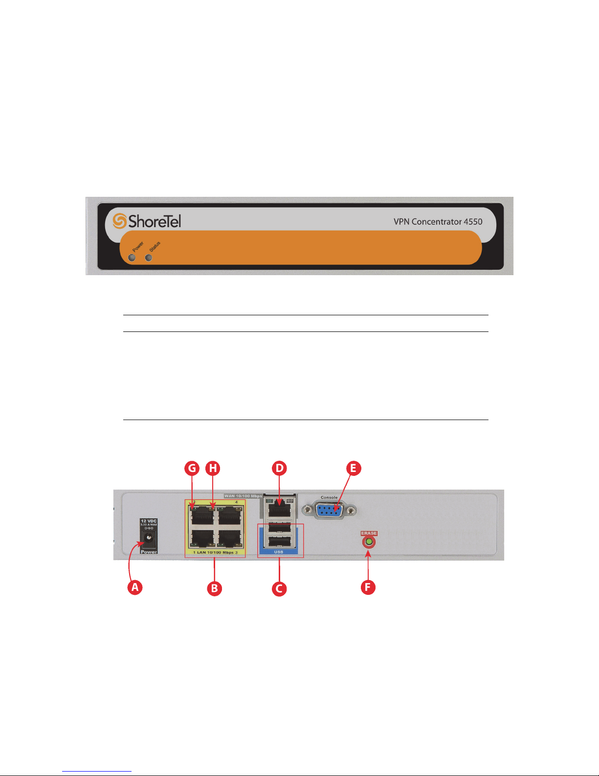
1.2.2 VPN Concentrator 4550......................................................................................................1
1.2.3 VPN Concentrator 5300LF.................................................................................................. 2
1.2.4 VPN Concentrator 5300LF2................................................................................................ 2
1.3 Components Included with the VPN Concentrator ............................................................... 2
1.4 Hardware Features................................................................................................................ 3
1.4.1 VPN Concentrator 4500 and 4550...................................................................................... 3
1.4.2 VPN Concentrator 5300LF and 5300LF2 ............................................................................ 5
1.5 Physical Installation ............................................................................................................... 8
1.5.1 Required Tools and Materials for Installation ..................................................................... 8
1.5.2 Desktop Installation ............................................................................................................ 9
1.5.3 Wall-Mount Installation (4500 and 4550) ............................................................................ 9
1.5.4 Rack-Mount Installation ....................................................................................................10
1.5.5 Connecting the VPN Concentrator to an AC outlet ......................................................... 11
1.6 Accessing the Web Configuration GUI ................................................................................ 12
1.6.1 Connecting to the Web Configuration GUI (4500/4550).................................................. 12
1.6.2 Connecting to the Web Configuration GUI (5300LF/5300LF2) ........................................ 13
1.7 Setting the IP Address for the VPN Concentrator .............................................................. 15
1.8 Deploying the VPN Concentrator Behind a Firewall ........................................................... 17
Chapter 2
2.1 System Overview ................................................................................................................ 19
2.2 Redundant VPN Concentrators ........................................................................................... 20
2.3 SSL VPN Authentication Mechanisms.................................................................................. 20
2.4 Other Features .................................................................................................................... 20
Chapter 3
3.1 Licensing.............................................................................................................................. 23
3.1.1 Viewing Preconfigured Licenses ....................................................................................... 23
3.1.2 Ordering Additional Licenses ........................................................................................... 24
3.1.3 Installing a License on a ShoreTel VPN Concentrator ...................................................... 25
Chapter 4
4.1 Configuring the VPN Concentrator ..................................................................................... 27
4.1.1 Configuring the Out of Band Management Port (VPN Concentrator 5300LF/5300LF2 Only)
.......................................................................................................................................... 27
4.1.2 Creating and Deleting VLANs .......................................................................................... 28
4.1.3 Connecting Remote VPN Clients to LAN Subnets ........................................................... 32
4.1.4 Viewing and Changing Link Settings for Ethernet Interfaces ........................................... 33
4.1.5 Configuring Stunnel.......................................................................................................... 36
4.1.6 Downloading, Creating, and Adding a Certificate ........................................................... 41
4.1.7 Configuring the Stunnel Username-Password Database .................................................. 46
4.1.8 Configuring the Stunnel MAC Whitelist Database ........................................................... 47
4.1.9 Configuring the Stunnel MAC Address Blacklist Database .............................................. 48

Contents
2
4.1.10 Viewing and Terminating Active Stunnel Session(s) ......................................................... 49
4.1.11 Enabling Remote System Logging ................................................................................... 50
4.2 Configuring VPN Parameters on IP Phones ........................................................................ 51
4.2.1 Configuring VPN Settings on IP Phones via config files ................................................... 52
4.2.2 Configuring VPN Settings Manually on the IP Phone....................................................... 52
4.2.3 Summary of the Recommended Phone Configuration and Deployment Procedure ....... 53
Chapter 5
5.1 Tools and Troubleshooting.................................................................................................. 55
5.1.1 Connecting to the CLI ......................................................................................................55
5.1.2 Viewing Network Information ........................................................................................... 55
5.1.3 Checking Network Connectivity ....................................................................................... 57
5.1.4 Viewing Log Files.............................................................................................................. 59
5.1.5 Packet Capture ................................................................................................................. 59
Appendix A
A.1 Firmware Upgrade .............................................................................................................. 61
A.2 Backup and Restore............................................................................................................. 65
A.2.1 Connecting to the CLI ......................................................................................................65
A.2.2 Using the Configuration Backup Command ..................................................................... 65
Appendix B
B.1 Console Port Pinout (5300LF2 only).................................................................................... 69

VPN Concentrator Installation and Configuration Guide 1
C
HAPTER
1
1.1 Overview
The ShoreTel VPN Concentrator securely connects remote IP phones to the rest of the
system, enabling IT staff to implement a very secure and flexible remote work policy.
Remote users simply connect a ShoreTel IP phone to a broadband router and with minimal
configuration, establish a secure tunnel to the ShoreTel VPN Concentrator. Once
connected, their phone acts as though it was located in the office.
The ShoreTel VPN Concentrator is offered in four models:
•Models 4500 and 4550 support up to 10 simultaneous VPN connections.
•Models 5300LF and 5300LF2 support up to 100 simultaneous VPN connections.
This guide covers hardware installation and firmware upgrade procedures for all four
models.
1.2 Specifications
1.2.1 VPN Concentrator 4500
1.2.2 VPN Concentrator 4550
WAN Ports 1 x 10/100 Ethernet
LAN Ports 4 x 10/100 Ethernet
Serial Ports 1 x RS-232
Dimensions Height 1.688“ (42.863 mm), Width 10.438 “ (265.113 mm), Depth
6.625 “ (168.275 mm)
Weight 2 lb (0.91 kg)
Power 12V @ 3A, external AC Adapter
Environmental Operating Temperature: 5° to 40°C
Humidity: 20% to 80%, non-condensing
WAN Ports 1 x 10/100 Ethernet
LAN Ports 4 x 10/100 Ethernet
Serial Ports 1 x RS-232
Dimensions Height 1.688“ (42.863 mm), Width 9“ (228.6 mm), Depth 6.625 “
(168.275 mm)
Weight 2 lb (0.91 kg)
Power 12V @ 3A, external AC Adapter
Environmental Operating Temperature: 5° to 40°C
Humidity: 20% to 80%, non-condensing

Components Included with the VPN Concentrator Chapter 1
2
1.2.3 VPN Concentrator 5300LF
1.2.4 VPN Concentrator 5300LF2
1.3 Components Included with the VPN Concentrator
The following components are included with the VPN concentrator:
•1 RJ45-to-DB9 console adapter (5300LF2 series only; for the pinout, see Appendix
B).
•2 rack mount brackets
•6 rack mount bracket screws
•Documentation CD
•License information sheet
•AC power cord
•MAC Address and Serial Number (affixed to the “belly” of the device)
•AC power adapter, with attached power cord (4500 and 4550 models only)
WAN Ports 1 x 10/100/1000 Ethernet
LAN Ports 1 x 10/100/1000 Ethernet
Management Ports 1 x 10/100/1000 Ethernet
Serial Ports 1 x RS-232
Dimensions 19” rack mount, 1RU
Weight 11.5 lb (5.28 kg)
Power 100/240v VAC, auto-selecting, 47 to 63 Hz
Environmental Operating Temperature: 0° to 40°C
Humidity: 10% to 90%, non-condensing
WAN Ports 1 x 10/100/1000 Ethernet
LAN Ports 1 x 10/100/1000 Ethernet
Management Ports 1 x 10/100/1000 Ethernet
Serial Ports 1 x RS-232
Dimensions 1RU. Height: 1.73” (44mm), Width 17.4” (443mm), Depth 11.5”
(292mm)
Weight 18 lbs (8.165 kg)
Power 100/240v VAC, auto-selecting, 47 to 63 Hz
Environmental Operating Temperature: 0° to 40°C
Humidity: 10% to 90%, non-condensing
Note:
If you have ordered additional licenses for the VPN, contact your
reseller.

Chapter 1 Hardware Features
VPN Concentrator Installation and Configuration Guide 3
1.4 Hardware Features
1.4.1 VPN Concentrator 4500 and 4550
The front and back panel of the VPN Concentrator models 4500 and 4550 are the same.
For the purposes of this guide, the VPN Concentrator 4550 is used as an example.
1.4.1.1 Front Panel (4550)
Figure 1-1 Front View of the 4550
1.4.1.2 Back Panel (4550)
Figure 1-2 Back View of the 4550
Component Description
Power LED Off – Power switch is off (or no power from the AC outlet)
Solid Green – Power is supplied to the unit
Status LED Off – The unit could not boot up because of self test failure
Solid Green – Self test passed.
Flashing Green – Configuration is being written to permanent
storage or an upgrade is in progress

Hardware Features Chapter 1
4
Component Description
APower Connector – Accepts the plug from the supplied power adapter
which can be connected to an AC outlet on the wall using the supplied
power adapter.
B4 Ports 10/100 Mbps LAN Switch – Four ports that can be used to connect
to the Local Area Network (LAN) network.
Note: Port 1 is assigned a pre-configured IP address of http://192.168.1.1.
Additional Note: LAN port 4 can be used as a port-based VLAN. LAN ports
1 through 3 can be used as a tag-based or port-based VLAN.
CUSB Ports – Not used.
DEthernet WAN Port – This port is used to connect the 4500/4550 to an
upstream router.
Note: This port requires an IP Address. If you do not know the IP Address
assigned to the WAN Interface, contact your system administrator.
EManagement Console Port – This port is used to establish a local console
session with the 4500/4550 using a VT100 terminal or emulation program.
The cable required is a straight-through 8-wire cable with female connector.
The serial port uses a baud rate of 9600, 8 data bits, 1 stop bit and no parity.
This port is used for debug or local diagnostic purposes only. Primary con-
figuration of the 4500/4550 is performed from a web browser as covered in
Chapter 3.
FErase
• If pressed twice in quick succession, the CLI password will be changed
to its original password.
• If pressed three times in quick succession, the4500/ 4550 will revert to
factory default settings. All passwords will be reset and all prior
configurations will be erased.
Note: The default LAN address is set to 192.168.1.1
Caution: Setting the system configuration to factory default will erase all
configuration changes.
GLink Status LED
•Solid Green – Ethernet link is up.
•Blinking Green – Indicates activity on the link.
HLink Speed LED
•Off – If the link is up, indicates that the port is connected to a 10BaseT
Ethernet switch or hub.
•Solid Amber – Indicates that the port is connected to a 100BaseT
Ethernet switch or hub.

Chapter 1 Hardware Features
VPN Concentrator Installation and Configuration Guide 5
1.4.2 VPN Concentrator 5300LF and 5300LF2
The front panel and back panel components differ for the VPN Concentrator 5300LF and
5300LF2 models as defined here.
1.4.2.1 VPN Concentrator 5300LF
Figure 1-3 Front Panel (5300LF)
Component Description
AErase
• If pressed twice in quick succession, the CLI password will be changed
to its default password.
• If pressed three times in quick succession, the 5300LF will revert to
factory default settings. All passwords will be reset and all prior
configurations will be erased.
Note: The default LAN address is set to 192.168.1.1
Caution: Setting the system configuration to factory default will erase all
configuration changes.
BPower LED
Off – Power switch is off (or no power from the AC outlet).
Solid Green – Power is supplied to the unit.
CDisk Activity LED
Off – No disk activity
Flashing Red – Data is being read or written to the disk.
Solid Red – System failure.
DPort 3 (Management Port) – Out of band management port used for configu-
ration purposes. This port is DHCP-enabled from the factory.
EPort 2 (WAN Port) – Connects to the WAN or upstream router. This port is
DHCP-enabled from the factory.
FPort 1 (LAN Port) – Connects to the local network or LAN.
Caution: The device is pre-configured with an assigned LAN IP Address of
http://192.168.1.1. Changing the LAN IP Address may result in loss of your
VPN connection.

Hardware Features Chapter 1
6
Figure 1-4 Back Panel (5300LF)
GReset – Used to do a hard reset of the system.
HConsole – DB9 serial (RS232) port (male connector) for CLI-based
configuration. The serial port uses a baud rate of 9600, 8 data bits, 1 stop bit
and no parity.
Component Description
APower Inlet
• Accepts a 3-pin 3-pin Shroud Female connector of a power cord with 3-
pin Shroud Male connector on the other end to connect to an AC outlet
(For power specifications, see the Specifications section at the
beginning of this manual).
BPower Switch – Turns the system power on and off.
CVGA Port – Not used.
D2xUSBports–Notused.
Component Description

Chapter 1 Hardware Features
VPN Concentrator Installation and Configuration Guide 7
1.4.2.2 VPN Concentrator 5300LF2
Figure 1-5 Front Panel (5300LF2)
Component Description
AErase
• If pressed twice in quick succession, the CLI password will be changed
to its default password.
• If pressed three times in quick succession, the 5300 will revert to factory
default settings. All passwords will be reset and all prior configurations
will be erased.
Note: The default LAN address is set to 192.168.1.1
Caution: Setting the system configuration to factory default will erase all
configuration changes.
BConsole Port – This port is used to establish a console session with the 5300.
CPower LED
Off – Power switch is off (or no power from the AC outlet).
Solid Green – Power is supplied to the unit.
DPort 3 (Management Port) – Can be used as an out-of-band management
port.
Caution: Once enabled, HTTP, SSH, SNMP, and TELNET sessions will only
be allowed through this port, and will no longer be available on Port 1 or
Port 2.
EPort 2 (WAN Port) – Connects to the upstream router.
Note: This port requires an IP Address. If you do not know the IP Address
assigned to the WAN Interface, contact your system administrator.
FPort 1 (LAN Port) – Connects to the local network or LAN.
Caution: The device is pre-configured with an assigned LAN IP Address of
http://192.168.1.1. Changing the LAN IP Address may result in loss of your
VPN connection.
G2xUSBports–Notused.
HDisk Activity LED
•Off – No disk activity
•Flashing Red – Data is being read or written to the disk.
IReset– Press the Reset button once to soft reboot the 5300. The 5300 will
reboot using the last saved configuration.

Physical Installation Chapter 1
8
Figure 1-6 Back Panel (5300LF2)
1.5 Physical Installation
The VPN Concentrator is designed for desktop, rack or wall-mount (4500/4550)
installation. Observe the following guidelines when installing the system:
•Never assume that the AC cord is disconnected from a power source. Always check
first.
•Never place objects greater than 5 lbs on top of the appliance as damage to the
chassis may result.
•Always connect the AC power cord to a properly grounded AC outlet to avoid
damage to the system or injury.
•Ensure that the physical location of the installation has adequate air circulation and
meets the minimum operating conditions as provided in the environmental
specifications for the system.
1.5.1 Required Tools and Materials for Installation
•A computer with Microsoft Internet Explorer.
•Ethernet cables to connect the LAN ports to LAN switches or other Ethernet
devices and the WAN port to a firewall or an upstream router.
•If the unit will be mounted on the wall (4500 and 4550):
— 1 Flat or Philips screw driver
— 2 round or flat head wood screws, Philips or slotted, and 1 ½ inch long. Refer
to Figure 1-7.
Component Description
APower Inlet– Accepts a 3-pin Shroud Female connector of
a power cord with 3-pin Shroud Male connector on the
other end to connect to an AC outlet (See Power for spec-
ifications).
BPower Switch – Turns the system power on or off.
CVGA Port – Not used.

Chapter 1 Physical Installation
VPN Concentrator Installation and Configuration Guide 9
— 2 hollow wall anchors
Figure 1-7 Diagram of round and flat head wood screws
•If the unit will be mounted in a rack:
— 1 Flat or Philips screw driver
— 2 rack-mount brackets
— 6 rack-mount bracket screws
1.5.2 Desktop Installation
1. Remove the unit and the accessories from the shipping container.
2. Place the unit on a flat, dry surface such as a desktop, shelf or tray.
1.5.3 Wall-Mount Installation (4500 and 4550)
You can mount the unit on a wall using the two built-in hang holes on the bottom of the
appliance. We recommend that you use two wood screws, at least 1 ½ inch long.
1. Install two screws 5.9063” (150 mm) horizontally apart on a wall or other vertical
surface. The screws should protrude from the wall so that you can fit the appliance
between the head of the screw and the wall. If you install the screws in drywall, use
hollow wall anchors to ensure that the unit does not pull away from the wall due to
prolonged strain from the cable and power connectors.
Tip:
If the ports will not be accessible or visible once the device is mounted
on the wall, connect a PC to the VPN Concentrator’s Ethernet port and
access the web configuration GUI to configure the device as described in
Section 1.6 and Section 1.7 before continuing.

Physical Installation Chapter 1
10
Figure 1-8 Distance between hang holes on the 4500/4550
2. Remove the unit and accessories from the shipping container.
3. Mount the unit on the wall as shown below.
Figure 1-9 Mounting position
Figure 1-10 Improper Mounting Position
1.5.4 Rack-Mount Installation
You can mount the unit in a 19” rack by using the rack-mount kit supplied with the
product.
1. Attach the ear mounts to both sides of the chassis with the supplied screws.
2. Attach the chassis to the rack post with screws.
WARNING
Do not mount the unit on the wall as shown below:

Chapter 1 Physical Installation
VPN Concentrator Installation and Configuration Guide 11
Figure 1-11 Attaching the Ear Mounts
1.5.5 Connecting the VPN Concentrator to an AC outlet
1. Plug the power cord attached to the Power Adaptor into the AC Power Connector on
the back of the device.
2. Plug one end of the included AC power cord into the Power Adaptor, and plug the power
cord’s “male” end into an AC outlet. Sometimes a little force is necessary to get the plug
properly positioned.
Make sure that the power LEDs are solid green and the disk activity LED is blinking red.
WARNING
Always connect the AC power cord to an AC outlet suitable for the
power supply that came with the unit in order to reduce the risk of
damage to the unit.
Tip:
If the device is on a shelf from which the power adapter will dangle,
secure the power adapter using a fastener or tie wrap to nearby shelf so
that it does not hang from the power connector.

Accessing the Web Configuration GUI Chapter 1
12
1.6 Accessing the Web Configuration GUI
You can configure the VPN Concentrator using the web configuration GUI. The device is
shipped with the pre-configured IP address 192.168.1.1 for the LAN ports.
1.6.1 Connecting to the Web Configuration GUI (4500/4550)
To connect to the web configuration GUI for the 4500/4550, follow these steps:
1. If you are connecting to the 4500/4550 for the first time:
a. Connect one end of an Ethernet cable to local LAN port 4 of the 4500/4550.
Connect the other end of the cable to your computer’s Ethernet port.
b. Assign static IP address 192.168.1.2 with subnet 255.255.255.0 to the Ethernet
interface of the computer that is connected to the LAN port of the 4500/4550.
c. Launch a web browser and enter the following URL:
http://192.168.1.1
2. If you are connecting to the 4500/4550 after initial network configuration:
a. Connect to any available LAN port, but only if VLANs have not been enabled.
If VLANs have been enabled, connect to LAN port 1.
b. Assign a static IP address and subnet that is on the same broadcast domain as
the LAN IP address provided by your system administrator.
c. Enter the LAN IP address provided by your system administrator.
3. Press Enter. The following login window appears.
Figure 1-12 Web Configuration GUI Login Window
4. Enter the username as “root” and the password as “default” to log into the system. The
System configuration page displays.
Note:
If initial network configuration has already been completed for this
device, you will need to obtain the device’s LAN IP address from your
system administrator to connect to this device.

Chapter 1 Accessing the Web Configuration GUI
VPN Concentrator Installation and Configuration Guide 13
Figure 1-13 System Page for the 4550
1.6.2 Connecting to the Web Configuration GUI (5300LF/5300LF2)
The 5300LF/5300LF2 is shipped with the pre-configured IP address 192.168.1.1 for the
LAN ports.
If are connecting to the 5300LF/5300LF2 for the first time, complete the following steps:
1. Connect one end of an Ethernet cable to the LAN port (port 1) on the 5300LF/5300LF2.
Connect the other end of the cable to your computer’s Ethernet port.
2. Assign static IP address 192.168.1.2 with subnet 255.255.255.0 to the Ethernet interface
of the computer that is connected to the 5300LF/5300LF2 LAN port 1.
Note:
The default user name and password for the device is “root” and
“default”. If this user name and password does not allow you to access
the device, it may have been changed. Obtain the user name and
password from your system administrator.
Note:
If initial network configuration has already been completed for this
device, you will need to retrieve from the system administrator the
device’s LAN IP address for LAN port 1 or the device’s management
interface LAN port 3.

Accessing the Web Configuration GUI Chapter 1
14
3. Launch a web browser on the PC and enter the following URL:
http://192.168.1.1.
If you are connecting to the 5300LF/LF2 after initial configuration, complete the following
steps:
1. Confirm with the system administrator if the Management Interface has been enabled.
If the Management Interface is enabled, you must connect to LAN port 3. Otherwise,
connect one end of an Ethernet cable to the LAN port of the 5300LF/5300LF2. Connect
the other end of the cable to your computer’s Ethernet port.
2. Assign a static IP address and subnet to your connecting computer that is on the same
broadcast domain as the LAN IP address provided by your system administrator.
3. Enter the IP Address for the LAN provided by your system administrator.
4. Press Enter. The following login window appears.
Figure 1-14 Web Interface GUI Login Window for the 5300LF/5300LF2
5. Enter the username as “root” and the password as “default” to log into the system. The
System configuration page appears.
Note:
The default user name and password for the device is “root” and
“default”. If this user name and password does not allow you to access
the device, it may have been changed. Obtain the user name and
password from your system administrator.
Other manuals for VPN Concentrator 4500
1
This manual suits for next models
3
Table of contents
Popular Gateway manuals by other brands

Moxa Technologies
Moxa Technologies MGate 5102-PBM-PN Quick installation guide

RTA
RTA 460MCMRS-N2EW Product user guide

Etross
Etross ETROSS-8888 user manual

Hartmann
Hartmann POE-ODM-MB quick start guide

ZyXEL Communications
ZyXEL Communications ZyWALL USG Series user guide

ICC
ICC DNET-1000 instruction manual