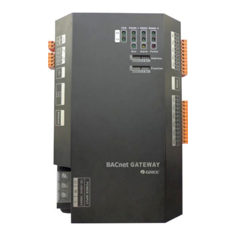
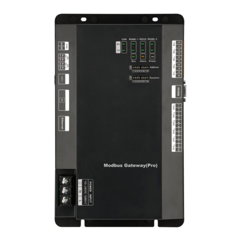
Gree ME30-44/D2 B User manual

Owner's Manual
Original Instructions
BACnet Protocol Gateway
Model:
ME30-44/D2(B)

To Users
Thank you for selecting Gree product. Before installing the product, please
read this instruction manual carefully to know well about the product and use it
correctly. In order to install and use the product correctly to reach the expected
operational effect, the following instructions are hereby issued:
(1)The appliance is not intended to be used by the people with physical,
sensory or mental handicap or the people without using experience and knowledge
(including children), except that they are supervised or guided by a person
responsible for their safety when using the appliance. Children should be
supervised to ensure that they do not play with the appliance.
(2)This instruction manual is universal manual, some functions introduced in
this manual are only applicable to specific products; all the illustrations and
information in this manual are only for reference, and the control interface should be
subject to the actual interface.
(3)In order to better meet the customers’ demand, our company will improve
the product continuously and we have the right to conduct necessary modification at
any time due to the reason of sales or production, and will reserve the right of
modification without further notification.
(4)We will bear no responsibility for the personal injury, property loss or
damage of equipment due to improper installation and debugging, unnecessary
maintenance, non-observance of related national laws, regulations, and industrial
standards, violation of any stipulations of this instruction manual, etc.
(5)The final authority for the interpretation of this instruction manual belongs
to Gree Electric Appliances, Inc. of Zhuhai.
Contents
1 Safety Notices (Please be sure to abide).........................1
2 User Notice.........................................................................2
3 Function and Parameter....................................................3
3.1 Functional Overview ...............................................................3
3.2 Parameter Specifications........................................................3
4 Parts and Assembly...........................................................3
5 Introduction for Gateway ..................................................4
5.1 Interface..................................................................................4
5.2 LED Display ............................................................................5
5.3 Button......................................................................................6
5.4 DIP Switch...............................................................................6
6 Application .........................................................................7
6.1 Building Management System (BMS).....................................7
6.2 Internet Topological Graph......................................................8
7 Product Installation ...........................................................9
7.1 Product Size and Spatial Size for Electric Control Cabinet
Installation.....................................................................................9
7.2 Gateway and BMS Communication Connecting Method......10
8 Attachment A TCP/IP Setting ..........................................16
9 Attachment B Applicable Model .....................................20

BACnet Protocol Gateway
1
1 Safety Notices (Please be sure to abide)
WARNING: If not abide strictly, it may cause severe damage to the unit or
the people.
NOTICE: If not abide strictly, it may cause slight or medium damage to the
unit or the people.
This sign indicates that the operation must be prohibited. Improper
operation may cause severe damage or death to people.
This sign indicates that the items must be observed. Improper operation
may cause damage to people or property.
WARNING!
This product can’t be installed at corrosive, inflammable or explosive
environment or the place with special requirements, such as kitchen. Otherwise, it
will affect the normal operation or shorten the service life of the unit, or even cause
fire hazard or serious injury. As for above special places, please adopt special air
conditioner with anti-corrosive or anti-explosion function.

BACnet Protocol Gateway
2
2 User Notice
Dear customer:
Please read this manual carefully prior to installation and operation and strictly
observe all installation and operation instructions covered in the manual.
Special attentions shall be paid to the following marks:
WARNING! This mark indicates operation, which if improperly performed, might lead to
the death or serious injury of the users.
CAUTION!
This mark indicates operation, which if improperly performed, might possibly
result in damage to the device.
WARNING!
Installation shall be performed by the qualified personnel; otherwise it would res
ult in a fire hazard or
electric shock.
Do not place the plug of the power supply into the socket before it is dried and cleaned.
Cut off the power supply before touching the electric element.
Do not touch this device with wet hands; otherwise it would result in electric shock.
Do use the power cable specified in this manual; otherwise it would result in a fire hazard.
When the power cable is reversely connected or the power supply is beyond the rated range, it
would result in a fire hazard or even damages to this device.
For PLUGGABLE EQUIPMENT, the socket-
outlet shall be installed near the equipment and shall be
easily accessible.
Do install this device inside the electric control cabinet which is located indoor and then is locked.
Do install this device where it will not be subject to the electromagnetic interference or heavy dust.
CAUTION!
Be sure the specified adaptor is used; otherwise this device would work improperly or even be
damaged.
Be sure this device is setup in place; otherwise it would result in communication fault.
Be sure the communication line is connected to the correct interface; otherwise it would result in
communication fault.
After connection, lines should be protected with insulating tape to avoid oxidation and short circuits.
Risk of explosion if battery is replaced by an incorrect type, dispose of used batteries according to
the instructions.
Normal working conditions for Gateway:
①Temperature : -20~60℃;
②Humidity: less than 85%,except for the condensation of dew;
③Lo
cation: indoor (it is highly recommended to install this product in the electric control cabinet), not
subject to direct sunlight, rain and snow etc.
Graphics in the instruction manual are for reference only.

BACnet Protocol Gateway
3
3 Function and Parameter
3.1 Functional Overview
Gree BACnet gateway ME30-44/D2(B) for multi VRF unit can realize data
exchange between air conditioner and BMS system and provide building interfaces
for standard BACnet/IP.Applicable models for this gateway are listed in Attachment
B.
The following BACnet protocol gateway ME30-44/D2(B) is shorted as gateway.
3.2 Parameter Specifications
3.2.1 Gateway TCP/IP Parameter (Default)
IP Address:192.168.0.200
Subnet Mask:255.255.255.0
Default gateway:192.168.0.1
CAUTION:After the TCP/IP parameters are altered, the gateway should be
restarted, then the parameters can come into effect.
4 Parts and Assembly
This kit includes the following parts. Please check before installation.
Gateway
1 set
Instruction manual
1 set

BACnet Protocol Gateway
4
5 Introduction for Gateway
5.1 Interface
5.1.1 Diagram of Interface Function
Fig. 5.1 Schematic of protocol gateway interfaces of multi VRF unit
5.1.2 Power
The input power supply is 24V DC, there are two power supply input interfaces,
only one is needed during operation; the power supply output is not applicable in
this device, please do not connect to electric appliance, otherwise it may cause
malfunction of gateway.
5.1.3 Communication Interface
CAN comm port: this device will not use this communication interface
temporarily.
RS485-1 comm port: connect to the unit(s) or the connection between adjacent
gateways.
RS485-2 comm port: this device will not use this communication interface
temporarily.
USB and SD card port: this device will not use this interface temporarily.
Ethernet comm port ETH0: realize communication through network cable and

BACnet Protocol Gateway
5
BMS.
Ethernet comm port CONFIG: this device will not use this interface temporarily.
5.2 LED Display
As shown in the picture below, open the black transparent front panel.
Fig 5.2 Schematic diagram of opening the black transparent board
Indicators, buttons and DIP switch are as shown below.
Fig 5.3 The schematic diagram of the gateway LED light board and DIP switch
The above LED indicator is mainly consist of two parts: status indicator (run,
power) and communication indicator (CAN and RS485). The following table is the
working status of each indicator.
CAN
RX
This device does not use this LED indicator.
TX
This device does not use this LED indicator.
RS485-1
RX
When the gateway receives data on the 485 bus, it blinks.
TX
When the gateway sends data to the 485 bus, it blinks.
RS485-2
RX
This device does not use this LED indicator.
TX
This device does not use this LED indicator.
STAT
When power supply of Gateway is normal, it is on.
BEAT
When Gateway is running normally, it blinks.

BACnet Protocol Gateway
6
BACKUP
This device does not use this LED indicator.
5.3 Button
SHT/DWN Hold the button for 5s and all indicators will be on; the gateway will be
reset and restarted.
BACKUP
Not use this button for this device temporarily.
5.4 DIP Switch
NOTICE!
Before using this device, please conduct DIP switch setting first, otherwise the
unit will not function normally!
Gateway dial-up setting area is consisting of function DIP switch code.
5.4.1 Diagram of Dial-up Machine
5.4.2 The 2st Lever of Functional DIP Switch—485 Bus Matched
Resistance Setting
The 2nd dial code of the function dialer is used for setting the matching
resistance of the gateway of 485 bus.
When the controller is at the beginning/end of the 485 bus, the controller needs
to be set to be with matching resistance, then the second bit of function dialer is set
to 1; when the controller is not at the beginning/end of the 485 bus, set the controller
to be without matching resistance, and set the dial code to 0.

BACnet Protocol Gateway
7
Fig. 5.4 Schematic of dial code
Fig. 5.5 Schematic diagram of scenes that should set DIP switch code
Fig. 5.6 Schematic diagram of scenes that no need to set DIP switch code
6 Application
6.1 Building Management System (BMS)
This gateway has provided BACnet standard protocols, which can connect to
building management system (BMS). It can monitor RS485 protocol Gree unit by
Building Management System through the gateway.

BACnet Protocol Gateway
8
6.2 Internet Topological Graph
Fig. 6.1 Communication network topology
Network topology instruction::
485 bus: 485 bus: The wire indicated by L2 in fig, 6.1 is 485 bus. One 485 bus
can connect 255 units at the most.
Cable: The wire indicated by L2 in fig. 6.2 is the normal cable. The gateway
can be connected to BMS by the cable.
Units’ quantity that can be connected to the gateway: One gateway can
connect 255 units at the most.

BACnet Protocol Gateway
9
7 Product Installation
7.1 Product Size and Spatial Size for Electric Control Cabinet
Installation
7.1.1 Product Size
Fig. 7.1 Gateway product size chart
Notice for installation and operation:
(1)Ensure the specification of power input. Otherwise, Gateway can’t work
normally or even be damaged.
(2)Ensure the dial code setting of Gateway is correct. Otherwise, there will
be communication malfunction.
(3)Ensure that the communication cord has connected to the correct
interface. Otherwise, there will be communication malfunction.
(4)Do not place Gateway in direct sunlight or high-temperature and humid
environment. Place it in the central control cabinet.
7.1.2 Spatial Size for Electric Control Cabinet Installation
Gateway shall be installed in electric control cabinet; the front of gateway shall
be hung upward and fixed with 4 screws. See the following fig (for reference).

BACnet Protocol Gateway
10
Fig. 7.2 Gateway installation guide
WARNING! Power cord and communication line of Gateway must conduct
routing separately (the distance shall be over 15cm); otherwise, it might lead to
Gateway communication malfunction!
The thin real line shown in the figure is communication wire and weak current
wire, the thick real line is strong current wire. Above lines are only for reference.
7.2 Gateway and BMS Communication Connecting Method
7.2.1 Material Selection for Communication Iine
(1) Model selection of Gateway and BMS communication line shall use
standard Ethernet communication line, the length of network cable between
gateway and router (computer, switchboard, etc.) shall not exceed 80m
(2) Communication line model selection for Gateway and AC unit
Wire type L(m)Communication
line between gateway
and AC units
Wire
diameter(mm2) Wire
standard Remark
Light-weight/normal
PVC jacket twisted
copper wire
L≤ 500 ≥ 2×0.75 IEC 60227-
5:2007
Total
communication
length shall not
exceed 500m

BACnet Protocol Gateway
11
7.2.2 Communication Connection Method
(1) Communication connection between Gateway and BMS
Fig. 7.3 Connecting method between gateway and router
(2) Communication connection between Gateway and AC units (n is the
quantity of unit(s), n ≤ 255)
Fig. 7.4 Connecting method of gateway
NOTICE! All communication connection lines under Gateway must be in series
connection, star connection shall not be adopted.

BACnet Protocol Gateway
12
7.2.3 Communication Connection Configuration
(1) Communication line connection between Gateway and PC:
Connection diagram between Gateway and PC user side:
1) Adopt cross connection network cable, Gateway shall directly connect
to PC.
Fig. 7.5 Gateway connects to personal computer directly
2) Adopt parallel network cable, Gateway shall go through router to
connect to PC.
Fig. 7.6 Gateway connects to personal computer via router
(2) Communication line connection between Gateway and AC units:
Models of U-Match/Rooftop unit (old models, please refer to Annex B):

BACnet Protocol Gateway
13
Models of U-Match/Rooftop unit (new models, please refer to Annex B):
(3) Gateway configuration:
One gateway can connect 255 units at the same time. After installation, the
parameters of gateway should be set. Before setting the parameters of gateway,
please set the IP address of PC as the same with the IP address in the same
network segment of gateway, as refer to appendix A; and then open the browser
(IE10 and above version, Firefox or Google), input the default IP address of
gateway: http://192.168.0.200, default user name: admin, password: 123456; as
shown below.
Fig. 7.7 Log on interface

BACnet Protocol Gateway
14
Gateway parameters configuration:
After selecting the language and inputting the account name and password,
click the arrow to enter the home page of gateway. Click “PRI” button at the column
bar in the upper right corner, see fig 7.8; then enter the page of gateway parameters
configuration, see fig. 7.9.
Fig. 7.8 Schematic diagram of “PRI” button
Fig. 7.9 Gateway parameters configuration page

BACnet Protocol Gateway
15
Parameters that can be set: gateway IP address (IP address setting: numbers
of master unit can’t all be 0; if they are all 0, it indicates the whole network, such as
192.168.0.0;numbers of master unit can’t all be 1; if they are all 1, it indicates
broadcast address, such as 192.168.0.255. It is not suggested to be set by users.
Otherwise, the gateway pages will unable to access), Gateway subnet mask,
defaulted gateway,device name and device ID. Users can configurate it by
themselves according to actual circumstances.
Default parameters:
①Access platform:Third-party;
②Access protocol:BACnet IP;
③Communication port :47808;
④OutTime:1000(ms).
After the parameter setting is completed, click Save and restart the gateway to
complete the configuration.
Caution! The default parameters should not be changed. Otherwise, the
gateway may not work normally.

BACnet Protocol Gateway
16
8 Attachment A TCP/IP Setting
This text takes Windows 10 as example to demonstrate the setting of TCP/IP.
(1)Left click the icon “Start” on the computer. When a new window
pops up, left click “Settings” to enter “Windows Settings”.
(2)Left click “Network & Internet” in the following picture to enter the interface
of “Network & Internet”. See ①in the picture below.
Fig 9.1 Windows settings
(3)Left click ”Network and Sharing Center” in the following picture. See ②
in the picture below.
Fig 9.2 Network and Sharing Center

BACnet Protocol Gateway
17
(4)Find “Ethernet” in the following picture. Left click “Ethernet” and enter the
interface of “Ethernet Status”. See ③in the picture below.
Fig 9.3 Ethernet settings selection
(5)Left click “Properties” in the following picture and enter the interface of
“Ethernet Properties”. See ④in the picture below.
Fig 9.4 Ethernet attribute selection
Table of contents
Other Gree Gateway manuals

Gree
Gree VRF User manual

Gree
Gree ME30-24/E5 User manual

Gree
Gree ME30-24/D1(BM) User manual

Gree
Gree ME30-24/E6 User manual

Gree
Gree ME30-24/E5 User manual

Gree
Gree ME30-24/F1 K User manual

Gree
Gree MG30-24/D1(B) User manual

Gree
Gree GMV BACnet Operating manual

Gree
Gree TDmetal Modbus Gateway User manual

Gree
Gree GRJW05-J User manual
Popular Gateway manuals by other brands

System air
System air X-RS485 user manual

Planet
Planet VIP-281 SW quick guide

Multitech
Multitech MULTIVOIP MVP-130FXS Specifications

Multitech
Multitech MultiConnect Conduit IP67 Base Station installation guide

Technica Engineering
Technica Engineering 1150 manual

APsystems
APsystems ECU-B Installation & user manual