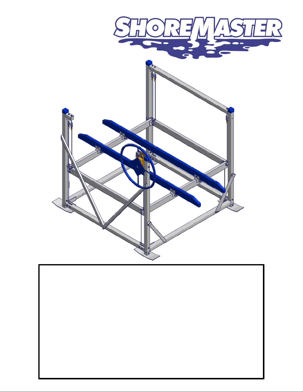
Shoremaster 1264 Instruction Manual
CAUTION - PUT SAFETY FIRST
Before attempting to install or operate this hoist, study and fully understand
the proper operating procedures and safety precautions outlined in this
owner's manual.
Never exceed the recommended weight capacity of your lift. The lifted
weight will include hull, engine, fuel, battery, and added accessories or
gear. Weigh your fully loaded boat at a certified scale to be absolutely
sure of the total weight.
Do not allow anyone on, in or under the lift while operating.
NOT COMPLYING WITH THE PROCEDURES AND PRECAUTIONS
OUTLINED IN THIS MANUAL WILL INVALIDATE THE WARRANTY AND
MAY RESULT IN PERSONAL INJURY OR DEATH.
If you have any questions about assembly, installation, operation or
suitability of this product, contact an authorized dealer.
1.
2.
3.
4.
5.
1264 Vertical Lift:
Instructions and Safety Tips
1200 lb. Capacity
Note: With 1502 DL Winch
10/1/13

11/12/2009 _1264 Complete Retail.idw
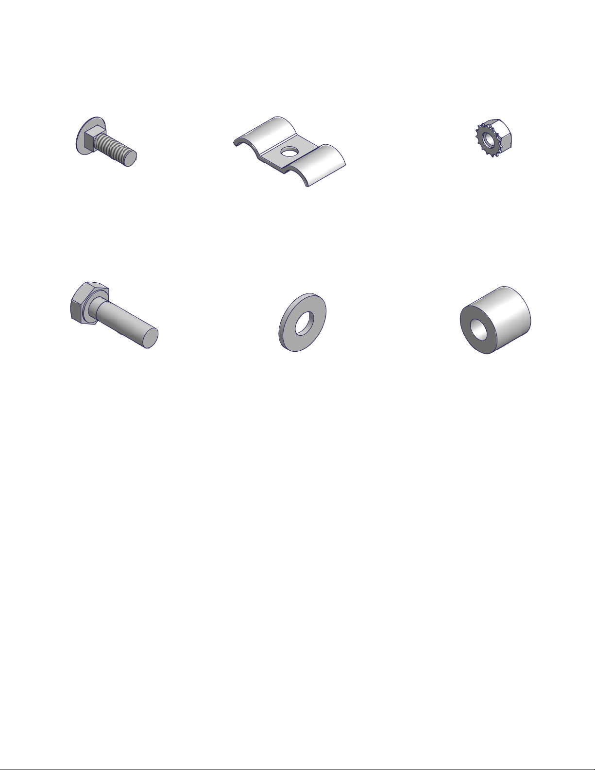
*Pulley Parts*
DESCRIPTIONPART NUMBERQTYITEM
Guide 1.0 - Plastic Guide Angle 2 x 2 x .5
10008504
Bolt Truss 1/4 - 20 x 3/410004774
Nut 1/4 Brass
10017974
Washer Lock 1/41002572
4
BRASS SHEEVE 3.125
100467310
BUSHING FRONT & SIDE100778912
SLEEVE FOR PULLEY10077902
BOLT TRUSS 3/8 X 2.25
10024308
NUT 3/8 NYLOC BRASS10024308
*1003932 - Bundle 1264 Vertical Lift*
DESCRIPTIONPART NUMBERQTYITEM
WHEEL100744811
Lift V Side100363812
Lift Opposite Side
100363913
Foot Pad 100363644
Bottom Beam100363725
Front Rack100740816
Front Rack Welded Only
10077581
Front Cable 10076691
Rack Side Right
100745217
Rack Side Tube10077941
Side Cable
10076651
Rack Side Left 100745118
Rack Side Tube10077941
Rear Rack100744319
Rear Rack Welded Only 10077911
Rear Cable
10076662
Leg Post1003112410
Lift Brace
1003084211
*1024595 - Hardware Box 1264*
DESCRIPTION
PART NUMBER
QTY
ITEM
Bunk Bracket
1005604
4
12
Hardware Bag - Winch 1002033113
Winch 1502 w/ Bolt Bag
1002028114
Cap Blue #15 - 2.313x2.3131001816415
*1004415 - Bolt Bag 1264*
DESCRIPTION
PART NUMBER
QTY
ITEM
Bolt 3/8 x 2.251002429816
Bolt 3/8 x 2.75
1002431817
Bolt 3/8 x 3.0 1002432418
Bolt 3/8 x 3.25
10024361019
Washer Flat 3/8 10025996320
Nut 3/8
10018032421
Nut Nyloc 3/810018051522
Nut Square 1/2
1001793423
Set Screw 1/2 x 1.25 1002563
4
24
Bolt Carriage 3/8 x 1.75 1001959225
Bolt 3/8 x 4.0
1002438226
Press-In Cap 1000986427
ShoreMaster
1264 Vertical Lift w/1502 Winch
Part Number: 1024594
PARTS LIST "A"
PARTS LIST "B"
PARTS LIST "C"
1
A
2
A
3
A
4
A
5
A
6
A
7
A
8
A
9
A
10
A
12
B
13
B
14
B
15
B
19
C
18
C
16
C
20
C
20
C
21
C
22
C
23
C24
C
11
A
27
C
Shipping Information
Description Weight Dimensions Cubic Ft
Bundle 145 LBS 7" x 65" x 68" 17.91
Hardware Box
26
C
25
C
17
C
WINCH HARDWARE KIT
CABLE CLAMP
QTY. ONE
NUT 1/4 W/
STAR WASHER
QTY. ONE
BOLT CARRIAGE 1/4 X .75
QTY. ONE
BOLT 5/16 X 1 NYLOC
QTY. ONE WASHER FLAT 5/16
QTY. ONE WHEEL SPACER
QTY. ONE
10/1/13

DETAIL A
DETAIL A
A
ASSEMBLY INSTRUCTIONS
Your safety is the most important issue related to this product.
Fully read and understand each step before proceeding with that step.
Wear protective gloves, clothing and eyewear when assembling and installing the lift.
Do not assemble, install or use this product if items are missing or damaged.
For ease of assembly find a flat area with plenty of room to assemble lift. The following tools will be
needed for assembling lift:
1. 7/16" Wrench
2. Pair of 9/16" Wrenches
3. Measuring Tape
4. Sharp Knife or Razor
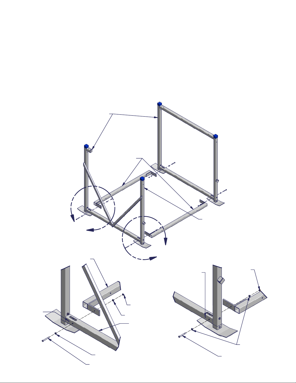
STEP 1
Slide Blue Caps on uprights as shown. Insert all four Leg Posts into Foot Pads, secure using one Bolt
3/8 x 2.75 and one Nut 3/8 in each place. Insert Leg Posts into Lift V Side and Lift Opposite
Side as shown. Use one Bolt 3/8 x 2.75, two Washers Flat 3/8 and one Nut 3/8 for each Leg
Post.
Blue Cap
Foot Pad
Leg Post
Lift Side
Nut 3/8
Washer Flat 3/8
Bolt 3/8 x 3.0
Bolt 3/8 x 2.75
Nut 3/8
10/1/13
DETAIL A
(Front Attachment)
DETAIL A
(Front Attachment)
DETAIL B
(Rear Attachment)
DETAIL B
(Rear Attachment)
A
B
STEP 2
Place the Lift V Side and Lift Opposite Side about 5 feet apart as shown. Attach one Bottom Beam
to the front of the Lift Sides. Secure to each side with one Bolt 3/8 x 3.25, two Washers Flat 3/8
and one Nut 3/8 - as shown in Detail "A."
Attach the other Bottom Beam to the rear of the Lift Sides. Secure to each side with one Bolt 3/8 x
3.25, two Washers Flat 3/8 and one Nut 3/8 - as shown in Detail "B."
NOTE: The front is indicated by the winch mount attachment - as shown.
NOTE: Bolt only one of the two holes at each corner at this time. The remaining hole will be used in
a later step. See Detail "A" and "B" for the connection holes to use at this time.
Bottom Beams
Lift Sides
Winch Mount
Attachment
Bottom Beam
Lift Side
Nut 3/8
Washer Flat 3/8
Washer Flat 3/8
Bolt 3/8 x 3.25
This hole
not used
at this time
This hole
not used
at this time
Washer Flat 3/8
Nut 3/8
Bolt 3/8 x 3.25
10/1/13

STEP 3
Attach both Lift Braces to the Bottom Beam with one Bolt 3/8 x 4.0, two Washers Flat 3/8 and one
Nut 3/8 - as shown.
Attach one Lift Brace to the T-slot on the front of each Lift Side with one Bolt Carriage 3/8 x 1.75, one
Washers Flat 3/8 and one Nut 3/8 - as shown. Attach by sliding bolt into T Slot then placing
brace over bolt, and gently tighten.
Take two measurements between the Lift Sides, diagonally. The two measurements should be the
same. Once lift is square, tighten all bolts.
Insert Press-In Caps into Lift Braces and Lift Side Diagonals.
Washer Flat 3/8
Nut 3/8
Bolt 3/8 X 4.0
Push-In Cap
Bolt Carriage 3/8 x 1.75
Lift Brace
Lift Side Diagonal.
DETAIL A
DETAIL A
DETAIL B
DETAIL B
A
B
STEP 4
Set Rack Side Right in the Lift V Side and the Rack Side Left in the Lift Opposite Side - as
shown.
NOTE: The bolt heads for the pulleys must be facing out.
A - Set Aluminum Eye end of cable in the slot of the front of the lift side bottom. Secure with one Bolt 3/8
x 3.25, two Washers Flat 3/8 and one Nut 3/8 - as shown in Detail "A."
B - Insert the Eye Bolt end of cable through the hole in the lift side top. Secure with one Washer Flat 3/8
and one Nut 3/8 Nyloc.
NOTE: Be sure the washer is in place and that the nyloc nut is tightend so at least 1/4" of Eye Bolt thread
is exposed.
Nut 3/8 Nyloc
Washer Flat 3/8
Bolt 3/8 x 3.25
Washer Flat 3/8
Nut 3/8
Aluminum Eye
end of cable
Eye Bolt end
of cable
10/1/13

DETAIL ADETAIL A
DETAIL BDETAIL B
DETAIL BDETAIL C
A
B
C
STEP 5
A - Attach the Rear Rack to each Rack Side. Secure at each end with two Bolts 3/8 x 2.25, four
Washers Flat 3/8 and two Nuts 3/8 Nyloc - as shown in Detail "A."
B - Set Aluminum Eye end of cable into the slot in the rear of the Lift Side bottom. Secure with one Bolt
3/8 x 3.25, two Washers Flat 3/8 and one Nut 3/8 - as shown in Detail "B."
C - Insert the Eye Bolt end of cable through the hole in the Lift Side top. Secure with one Washer Flat
3/8 and one Nut 3/8 Nyloc - as shown in Detail "C.".
NOTE: Be sure the washer is in place and that the nyloc nut is tightend so at least 1/4" of Eye Bolt
thread is exposed.
Nut 3/8 Nyloc
Washer Flat 3/8
Use this hole
Eye Bolt
Lift Side
(top)
Bolt 3/8 x 2.25
Rack Side
Rear Rack
Nut 3/8 Nyloc
Washer Flat 3/8
Lift Side
(bottom)
Bolt 3/8
x 3.25
Washer Flat 3/8
Nut 3/8
Aluminum Eye
end of cable
10/1/13

DETAIL ADETAIL A
DETAIL BDETAIL B
A
B
STEP 6
Set the Front Rack in place and attach to the Rack Sides. Secure at each end with two Bolts 3/8 x 2.25,
four Washers Flat 3/8 and two Nuts 3/8 Nyloc - as shown in Detail "A."
Insert the Eye Bolt end of cable through the hole in the Lift Side top. Secure with one Washer Flat 3/8
and one Nut 3/8 Nyloc - as shown in Detail "B." The other end of the cable will be attached to the
Winch 1202.
NOTE: There are five Eye Bolts to attach. See
the drawing of Eye Bolts and cables on page
16 to ensure correct location.
NOTE: Firmly tighten all nuts and bolts at this time.
NOTE: Nyloc nuts should not be reused. If a nyloc nut is removed it must be replaced with a new one.
Bolt 3/8 x 2.25
Washer Flat 3/8
Nut 3/8 Nyloc
Rack Side
Front Rack
Nut 3/8 Nyloc
Washer Flat 3/8
Lift Side
Eye Bolt
10/1/13

DETAIL ADETAIL A
A
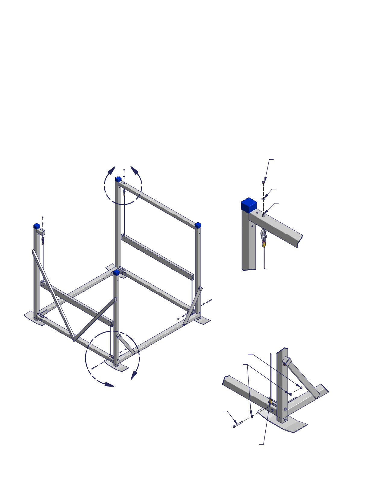
STEP 7
Route the Winch Cable in between the two cross-bolts of the
Winch. Insert the Winch Cable through the hole in the
Winch Hub and create a loop around the square hole.
Secure with one Bolt Carriage 1/4 x .75, one Cable Clamp, and
one Nut 1/4 w/ Star Washer as shown in Detail "A."
NOTE: Wear leather gloves while handling the cables.
STEP 8
Attach the Winch to the Winch Upright with two Bolts 3/8 x 3.25, four Washers Flat 3/8, and two
Nut 3/8 Nyloc - as shown.
NOTE: The Bolt Heads should be positioned on the Winch side and should protrude through the Winch
and out the Winch Upright - as shown.
NOTE: The Wheel Shaft of the Winch must be facing
to the outside of the lift - as shown.
GOOD Cable
Route BAD Cable
Route
Bolt Carriage
1/4 x .75
Cable
Clamp
Nut 1/4 w/
Star Washer Winch
Cable
Nut 3/8 Nyloc
Washer Flat 3/8
Bolt 3/8
x 3.25
Winch
Washer
Flat 3/8
Winch
Upright
10/1/13
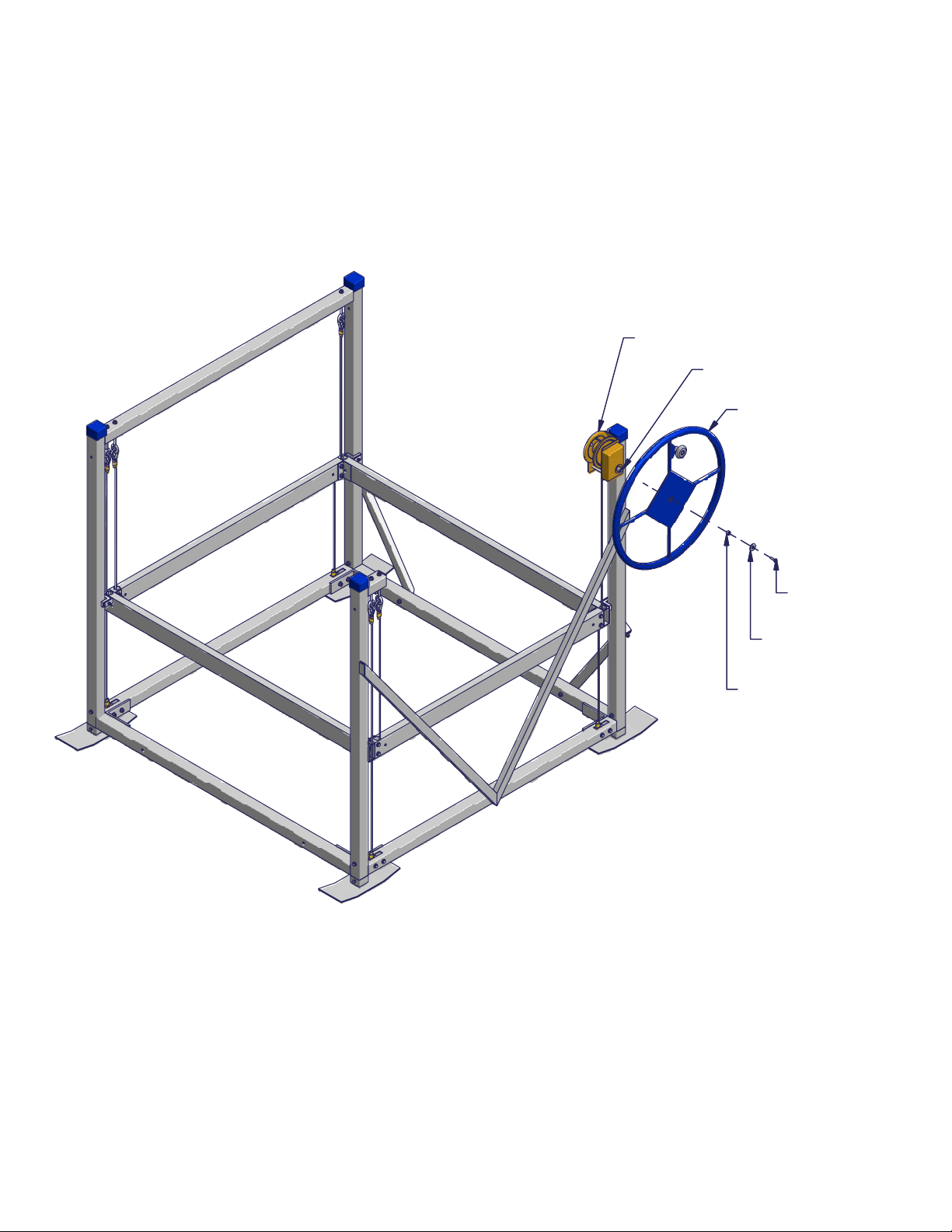
STEP 9
Thread Wheel clockwise onto Wheel Shaft until it touches the Brake Pad. The wheel must be fully
against Brake Pad and a clicking sound must be heard when turning wheel up!
Using a sharp knife or razor blade, cut a small hole in the middle of the Wheel, where the wheel sticker
covers the attaching bolt hole.
Secure Wheel to Winch using one Bolt 5/16 x 1 Nyloc, one Washer Flat 5/16, and one Wheel
Spacer - as shown.
STEP 10
Thead excess cable onto winch hub by turning the wheel clockwise. Be sure cable wraps tight and
uniformly on hub with each strand lying snuggly next to the adjacent strand. Keep tension on the cable
by holding it tight when turning the wheel to develop a proper wrap. Do not allow cable to wind up
loosely on hub.
CAUTION
Use a leather glove or other hand protection to avoid cuts when applying cable pressure. Cables
wrapping incorrectly will result in rapid cable wear.
Winch
Wheel Shaft
Wheel
Bolt 5/16
x 1 Nyloc
Washer
Flat 5/16
Wheel
Spacer
10/1/13

DETAIL ADETAIL A
A
STEP 12
Make sure that all nuts and bolt are firmly tightened.
NOTE: Do not over tighten any connection using nyloc nuts or set screws.
STEP 11
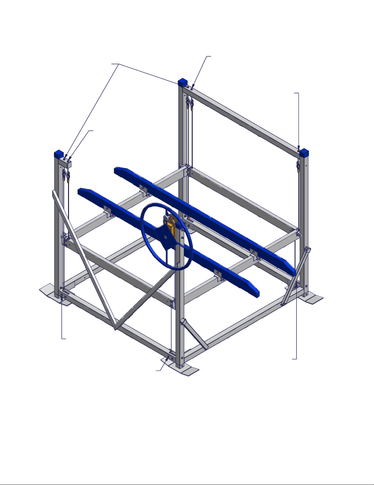
Position the Bunk Bracket on Front and Rear Racks to fit watercraft. Secure each Bunk Bracket with
one Nut 1/2 Square, and one Set Screw 1/2 x 1.25 - as shown in Detail "A."
Attach optional ShoreMaster Carpeted Bunks to the Bunk Brackets with one Bolt 3/8 x 2.75, two
Washers Flat 3/8, and one Nut 3/8 in each place - as shown in Detail "A."
Bunk Bracket
Set Screw
1/2 x 1.25
Front Rack
Nut 1/2 Square
Nut 3/8
Washer Flat 3/8
Bolt 3/8 x 2.75
10/1/13
CAUTION
Be sure washer is in place and that Nyloc Nut is tightened so at least 1/4" is exposed. Failure to attach
cables, Eye Bolts, Washers and Nyloc Nuts correctly could result in a severe crushing, cutting or pinching
injury. Severe damage to lift or boat could also occur.
Proper Cable Locations
Front Rack (winch)
Cable Eye Bolt
Rear Rack Cable
Eye Bolt
Rear Rack Cable
Attached here
Right Rack Side Cable
Attached here
Left Rack Side Cable
Attached Here Front of Lift
Front of Lift
Rack Side Right
Cable Eye Bolt
Rack Side Left
Cable Eye Bolt
10/1/13
DETAIL ADETAIL A
A
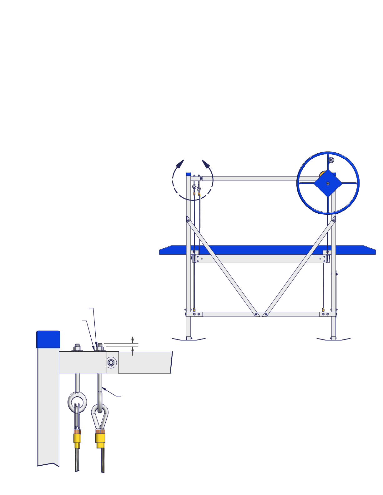
Proper Cable Adjustment
a) There are four cables with Eye Bolts and nuts that must be adjusted to properly level cables.
These Eye Bolts are all located near the rear uprights as shown.
b) Turn wheel so front rack beam raises about 6" above the bottom of frame. Adjust cables so
all corners of rack are the same distance from frame.
NOTE: Adjust the cable length by turning the nut on top of the Eye Bolt. Hold the Eye Bolt stationary
while adjusting the top nut. Using the frame below the rack as your reference point, measure the
distance from frame to rack in each corner. These distances should all be within a 1/4 inch.
NOTE: Be sure washer is in place and that Nyloc Nut is tightened so at least 1/4" of Eye Bolt thread
is exposed.
Nut 3/8 Nyloc
Washer Flat 3/8
Eye Bolt
1/4"
10/1/13

INSTALLATION INSTRUCTIONS
Do not under any circumstances, endanger yourself or risk damage to your lift or boat when
installing.
• Situations will widely vary between installation sites. ShoreMaster recommends that your
dealer or other trained boat lift installer train you and perform the initial installation.
• Wear protective gloves, clothing and eyewear when assembling and installing the lift.
• Do not assemble, install or use this product if items are missing or damaged.
The following are guidelines or suggestions for installation:
STEP 1
Measure the water depth of the position you want to locate the lift. Measurements should
be taken at both the projected position of the end nearest shore and end furthest from
shore.
STEP 2
Before installing, adjust lift legs so the boat can float into position before raising, while still
allowing a high enough position so the boat can be fully raised up and out of the water.
STEP 3
Carry, lift or slide the lift into position alongside the dock.
STEP 4
Ensure that your lift is level. Measure the distance from the top of the cross beam to the
water surface. The distance at each of the four corners of the lift should be within two
inches of each other. If they are not, adjust the legs accordingly.
Note: If the lift legs will extend 3 feet or more, ShoreMaster recommends deep water
braces to stabilize and strengthen the lift. Ask your dealer for more information.
STEP 5
CAUTION
The lift must be resting on the water bottom in a level, secure and
stable position for safe operation. An unstable lift installation could
result in tipping of the lift during operation, causing damage to
watercraft and a crushing or pinching injury to the operator or
bystanders.
10/1/13
Position the Bunk Bracket to fit watercraft so that it does not come in contact with the frame
of the lift. After loading and operating the lift pursuant to the operating instructions, remove
the boat and recheck that the lift remains level.

OPERATING INSTRUCTIONS
Now that you have installed and leveled the lift, you are ready to raise your boat for the first time.
Prior to use, see to it that anyone who may use the lift looks upon the unit not as a toy but a piece
of heavy equipment that deserves your respect and good judgment.
• Before allowing anyone to operate the lift, be sure they fully understand the proper operating
procedure.
• Do not exceed maximum capacity of the lift; overloading may cause mechanical failure and
serious personal injury.
• Do not allow anyone who is in the water within six feet of the lift.
• Do not allow anyone on, in or under the lift while operating.
When operating the lift, the following procedures should be adhered to:
STEP 1
Be sure the lift rack and cradles or bunks are positioned below the water surface so they
will not interfere with the boat floating into position.
STEP 2
Properly balance and center the boat on the lift prior to raising. The boat should be
positioned with the center of gravity near the middle of the lift. For most rear engine
mounted boats, this requires you to position the boat somewhat forward in the lift.
STEP 3
Turn wheel in direction of arrow (clockwise) to raise lift. A clicking
sound is heard when properly raising lift. Turning wheel and
wrapping cable in wrong direction may cause fast spin down of wheel.
WARNING
Stay clear of lifts (facing wheel) while operating. Do not allow anyone on, in or under lift.
A cable or lift part failure can cause a sudden drop of boat, resulting in a crushing or falling
injury or death!
CAUTION
Do not touch wheel or attempt to stop it if fast spin down of wheel occurs. Placing hands
or feet on spinning wheel can cause broken or cut limbs.
STEP 4
Carefully bring the lift up until the bunks or cradles have secured the boat. Then, stop the
lift and check to see that the bunks or cradles have automatically positioned themselves to
the shape of the hull, as they are designed to do. If so, continue bringing the boat out of
the water until it is about one foot above the surface. Stop the lift again and check the
stability of the lift, particularly to see that it is fairly level and will not topple over. Finally,
continue lifting the boat while paying close attention to the positioning of the lift until it is at
its desired height.
CAUTION
When first using the boat lift after installation, the weight of the boat may
cause the lift to settle and become unbalanced. Until you are certain the
lift has stabilized, make sure people are not in the immediate vicinity of
the lift.
10/1/13

CAUTIONS:
1. Do not over raise lift rack. Stop before top of rack hits cable loops attached to Eye Bolts. Over raising
could cause damage to winch, cables or other parts.
2. Do not over lower rack so slack develops in cable. Doing this could cause cable to jump off winch
spool. This may result in sloppy wrapping of cable next time you raise the lift, resulting in premature
wear or cable breaking.Turn wheel down one or two turns past point when craft begins to float (This
must always be at some point before lift rack is contacting rear bottom beam). Then turn wheel up
slightly until clicking sound is heard to secure wheel position and brake on winch.
3. Properly cover your boat, or pull your boat's plug when the boat is in a raised position. Rain water
accumulating in your bilge can quickly increase your gross weight over the capacity of the lift.
4. Do not leave lift, or boat on lift, in water if ice formation is possible. Ice can severely damage your
boatlift.
STEP 5
After loading and operating the lift, remove the boat and recheck that the lift remains level. (See
Step 4 of the Installation Instructions.) If the lift is not level, the legs should be adjusted accordingly.
Because the lift may settle and become unbalanced, the lift levelness should be rechecked two
weeks after installation and periodically as needed.
STEP 6
If lift is without a boat in it for more than one day, raise the rack (pulleys) fully out of the water
to help prevent corrosion of these parts. At all times, make sure the boat is stored high enough
out of the water to avoid wave action against the hull. A moving boat as a result of wave action
will damage the lift and can take the boat off the lift.
Monthly Checks
Check cables for frays, corrosion or breaks at least once a month. A cable breaking while
boat is in lift could damage boat or lift. Severe bodily injury could also occur.
SAFETY MAINTENANCE
1. Inspect nuts and bolts for damage, wear or loose connections. Tighten or replace parts as needed.
2. Inspect lift frame, pulleys, winch and pivot points for unusual wear, damage or bent parts. Replace
or repair as needed.
3. Check that the rack is level with the bottom frame of your lift. Cable stretching or settling of lift could
require you to adjust nuts on Eye-Bolts.
4. Lubricate winch and wheel threads. Do not get lubricant on brakepads! Brake will fail and wheel will
spin down if brake pads are lubricated.
5. Check and lubricate pulleys to ensure that they are turning freely.
6. Check Eye-Bolts to make sure they are not working themselves loose.
ShoreMaster dealers usually offer service visits. Please contact them if you are unable or unwilling
to perform maintenance or service to lift.~
Spring and Fall Checks
10/1/13
Table of contents
Other Shoremaster Lifting System manuals


