Shoremaster ShorePort 1022950 User manual
®
Shoreport
SHOREMASTER.COM
Shoreport
PRODUCT ASSEMBLY INSTRUCTIONS
To avoid the risk of personal injury or death, study and fully understand the proper installation
and operating procedures and safety precautions outlined in this owner’s manual.
NOT COMPLYING WITH THE PROCEDURES AND PRECAUTIONS OUTLINED IN THIS
MANUAL MAY RESULT IN PERSONAL INJURY OR DEATH AND WILL INVALIDATE THE
WARRANTY.
Use caution when handling gasoline; plastic creates static electricity and may ignite flamable
gases or liquids resulting in burns.
Never jump or dive into the water before the entire subsurface area has been checked for
depth. Not doing so may result in personal injury or death.
Do not run on the ShorePort; the ShorePort has uneven surfaces and may be slippery when
wet causing a falling injury.
Check bolts periodically to ensure hardware and connectors remain securely fastened.
If you have any questions about assembly, installation, use or suitability of this product,
contact an authorized dealer or ShoreMaster directly at 800-328-8945.
- PUT SAFETY FIRST
1.
2.
3.
4.
5.
6.
7.
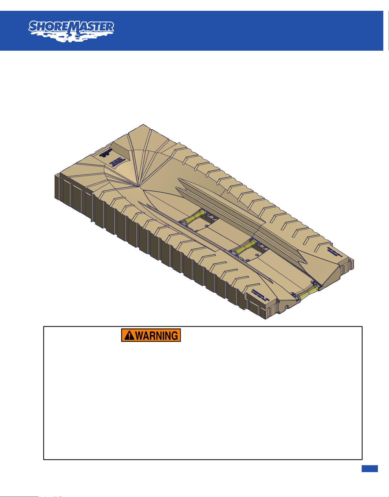
ShorePort PWC Lift
Instructions
1022950 - 58" x 138" Tan ShorePort
1029301 - 58" x 138" Gray ShorePort

® ®
Shoreport
SHOREMASTER.COM
Parts List
DESCRIPTION
PART NUMBER
QTY
ITEM
Keel Roller Rear Assembly
100178611
Washer Flat 3/8 SS
100259942
3/8 x 3/4 Button Head Socket Cap Screw
1001788
4
3
Keel Roller Assembly with Hardware10065951
-
Front Keel Roller Assembly
10017761
4
Shoreport 58" x 138"
-
1
5
Washer Flat 3/8 x 1.25 x .125 Rubber
1000613
4
6
Keel Roller Spacer Kit
10034751
-
3/8 x 1-1/2 Button Head Cap Screw
1000655
4
7
Keel Roller Spacer Plate
101337528
Optional Float (adds 50lbs cap each)
100423669
3/8 x 2-1/4 Flat Head Machine Screw
100050521 0
8" Plastic Cleat
100108911 1
1
5
3
2
ShorePort Parts List
Instructions
6
4
9
10
Note: The front of the ShorePort is 16" tall and will have a freeboard of about 14" without a PWC on it. The
rear roller should rest about half way out of the water without a PWC on it. The freeboard can be increased
by adding supplemental floatation (item 10).
11
Not complying with the
procedures and precautions outlined in
this manual may result in personal injury
or death and will invalidate the warranty.
Step 1. You may need to adjust rollers for best results. See next page
for adjustment options.
Step 2. See Shoreport anchoring and attachment options page for
available methods to anchor the Shoreport. (Pile guides, flexi-hinges,
connectors, etc.)
Note: Add optional floats if necessary. (adds 50lbs each)
4
8
2
3
DETAIL Position - A DETAIL Position - B
DETAIL Position - C DETAIL Position - D
DETAIL Position - E
DETAIL Position - F
DETAIL Position - G
Position - A
Position - B
Position - C
Position - D
Position - E
Position - F
Position - G
ShorePort Keel Roller Adjustment
Instructions
The rollers on the Shoreport have multiple adjustment locations in order to adjust the Shoreport to your personal
water craft.
The front and middle rollers can be placed in three different slots and can also be flipped with axle above or below the
plates. The rear roller can also be flipped but has only one location.
To adjust, use a 7/32" hex key to remove the four 3/8 button head bolts holding the roller in, move to desired position,
and put the bolts back in to secure in place.
For PWC's that are difficult to unload we recommend having the front roller in the most forward position with the axle
flipped above the plates (Position B) so it is the highest it can be and the middle roller in the most forward position
with the axle facing down into the slots of the Shoreport (Position C).
With the many different designs of PWC's available you will need to adjust the rollers to fit your specific watercraft. As
a general guideline, raising the front and middle rollers makes it easier to unload the PWC. However if the rollers are
too high the PWC may not stay on the Shoreport and the rollers may need to be lowered. If the rollers do not provide
enough height in the forward position with the axle up, there is a spacer kit available to raise the roller another 1/2
inch, part number 1003475 as shown in Position A.
-The keel rollers on the ShorePort may be adjusted to make it
easier to get your PWC on and off of the ShorePort.
-The middle and front rollers can be adjusted in the different
positions as shown. The axle of the roller assembly can be
positioned facing up or down and can be placed in any three of
the roller positions.
-To move the rollers use a 7/32" hex key wrench and remove
the four 3/8" button head bolts holding the roller to the
ShorePort. Move the roller to the desired position and
re-attach using the same 3/8" button head bolts. For further
adjustment a Keel Roller Spacer kit (P/N: 1003475) is
available and can be used in positions D,E, and F as shown in
position G.
-The rear keel roller may also be adjusted by flipping it over so
the axle for the roller is on top of the mounting plates. Roller
positioning will vary depending on the type of PWC you have.
You will have to try different roller positions to find what works
best for your PWC.
A B CD E
A - Highest Position with Spacer Kit
B - Highest Position no Spacer Kit Axle Up
C - Roller in Forward (High) Position
D - Roller in Middle Position
E - Roller in Rear (Low) Position
The front and middle rollers can be used in
all of the above positions. Positions D and E
can also be used with the axle up. The axle
needs to be up in order to use the spacer kit.
The spacer kit can be used in any of the
three slots.
To the left, recommended roller position for
PWC's that are difficult to remove from the
Shoreport. Front roller in position B, middle
roller in position C.

®
®
Shoreport
SHOREMASTER.COM
Parts List
DESCRIPTION
PART NUMBER
QTY
ITEM
Keel Roller Rear Assembly
100178611
Washer Flat 3/8 SS
100259942
3/8 x 3/4 Button Head Socket Cap Screw
1001788
4
3
Keel Roller Assembly with Hardware10065951
-
Front Keel Roller Assembly
10017761
4
Shoreport 58" x 138"
-
1
5
Washer Flat 3/8 x 1.25 x .125 Rubber
1000613
4
6
Keel Roller Spacer Kit
10034751
-
3/8 x 1-1/2 Button Head Cap Screw
1000655
4
7
Keel Roller Spacer Plate
101337528
Optional Float (adds 50lbs cap each)
100423669
3/8 x 2-1/4 Flat Head Machine Screw
100050521 0
8" Plastic Cleat
100108911 1
1
5
3
2
ShorePort Parts List
Instructions
6
4
9
10
Note: The front of the ShorePort is 16" tall and will have a freeboard of about 14" without a PWC on it. The
rear roller should rest about half way out of the water without a PWC on it. The freeboard can be increased
by adding supplemental floatation (item 10).
11
Not complying with the
procedures and precautions outlined in
this manual may result in personal injury
or death and will invalidate the warranty.
Step 1. You may need to adjust rollers for best results. See next page
for adjustment options.
Step 2. See Shoreport anchoring and attachment options page for
available methods to anchor the Shoreport. (Pile guides, flexi-hinges,
connectors, etc.)
Note: Add optional floats if necessary. (adds 50lbs each)
4
8
2
3
DETAIL Position - A DETAIL Position - B
DETAIL Position - C DETAIL Position - D
DETAIL Position - E
DETAIL Position - F
DETAIL Position - G
Position - A
Position - B
Position - C
Position - D
Position - E
Position - F
Position - G
ShorePort Keel Roller Adjustment
Instructions
The rollers on the Shoreport have multiple adjustment locations in order to adjust the Shoreport to your personal
water craft.
The front and middle rollers can be placed in three different slots and can also be flipped with axle above or below the
plates. The rear roller can also be flipped but has only one location.
To adjust, use a 7/32" hex key to remove the four 3/8 button head bolts holding the roller in, move to desired position,
and put the bolts back in to secure in place.
For PWC's that are difficult to unload we recommend having the front roller in the most forward position with the axle
flipped above the plates (Position B) so it is the highest it can be and the middle roller in the most forward position
with the axle facing down into the slots of the Shoreport (Position C).
With the many different designs of PWC's available you will need to adjust the rollers to fit your specific watercraft. As
a general guideline, raising the front and middle rollers makes it easier to unload the PWC. However if the rollers are
too high the PWC may not stay on the Shoreport and the rollers may need to be lowered. If the rollers do not provide
enough height in the forward position with the axle up, there is a spacer kit available to raise the roller another 1/2
inch, part number 1003475 as shown in Position A.
-The keel rollers on the ShorePort may be adjusted to make it
easier to get your PWC on and off of the ShorePort.
-The middle and front rollers can be adjusted in the different
positions as shown. The axle of the roller assembly can be
positioned facing up or down and can be placed in any three of
the roller positions.
-To move the rollers use a 7/32" hex key wrench and remove
the four 3/8" button head bolts holding the roller to the
ShorePort. Move the roller to the desired position and
re-attach using the same 3/8" button head bolts. For further
adjustment a Keel Roller Spacer kit (P/N: 1003475) is
available and can be used in positions D,E, and F as shown in
position G.
-The rear keel roller may also be adjusted by flipping it over so
the axle for the roller is on top of the mounting plates. Roller
positioning will vary depending on the type of PWC you have.
You will have to try different roller positions to find what works
best for your PWC.
A B CD E
A - Highest Position with Spacer Kit
B - Highest Position no Spacer Kit Axle Up
C - Roller in Forward (High) Position
D - Roller in Middle Position
E - Roller in Rear (Low) Position
The front and middle rollers can be used in
all of the above positions. Positions D and E
can also be used with the axle up. The axle
needs to be up in order to use the spacer kit.
The spacer kit can be used in any of the
three slots.
To the left, recommended roller position for
PWC's that are difficult to remove from the
Shoreport. Front roller in position B, middle
roller in position C.

® ®
Shoreport
SHOREMASTER.COM
How to Grease Rollers
If your keel rollers are hard to turn, you can add
grease to them by using a grease gun with a
snap in needle (the needle can be purchased
from ShoreMaster with part number 1017538 or
through a parts store). To add grease to the keel
roller you will have to make sure your ShorePort
came with the keel rollers that have a small hole
drilled into the middle of the roller. If you have
the hole, insert the needle on the grease gun into
the hole and pump grease into the roller until
grease comes out the end of the roller. If your
keel rollers do not have the hole in the middle of
them you can insert the needle between the
roller and the shaft the roller rides on and pump
grease into it until it comes out the other end. If
the roller is still hard to turn the keel roller is
probably bent and will have to be replaced.
Note: Use marine grade grease.
Keel Roller
ShorePort
Grease Access Hole
DETAIL F
SCALE 1 / 25
DETAIL G
SCALE 1/20
F
G
ShorePort Anchoring and Attachment Options
ShorePort to Poly Dock
Front Connector
P/N: 1007011 - Tan
1029365 - Gray
ShorePort to ShorePort
Side Front Connector
P/N: 1006631 - Tan
1029360 - Gray
ShorePort to ShorePort
Notched Side Front Connector
P/N: 1003472 - Tan
1029359 - Gray
ShorePort to ShorePort
Side Rear Connector
P/N: 1007016 - Tan
1029358 - Gray
Single Hinge Assembly
ShorePort to Floating Dock
(In calm water).
P/N: 1007015 (Pair)
Heavy Duty Pipe
Bracket with
connector
P/N: 1022952 - Tan
1029310 - Gray
Small Pipe Bracket
(works best on side of
ShorePort)
P/N: 1022953 - Tan
1029312 - Gray
ShorePort Rear Pipe Bracket
(works only on side of
ShorePort)
P/N: 1022951 - Tan
1029314 - Gray
Heavy Duty Pipe
Bracket with Chain
Guide
P/N: 1023737 - Tan
1029304 - Gray
Stand-off Bracket
Secures Pipe to Dock
P/N: 1006715 (Pair)
2.375
0.150
2" Schedule 40 Pipe (2-3/8" O.D.)
3' Pipe P/N:1007729
5'-3" Pipe P/N:1007732
7' Pipe P/N:1007736
10'-6" Pipe P/N:1007737
21' Pipe P/N:1002676
Side Mount Flexi-Hinge
Assembly ShorePort to
Floating Dock
P/N: 1013365

®
®
Shoreport
SHOREMASTER.COM
DETAIL F
SCALE 1 / 25
DETAIL G
SCALE 1/20
F
G
ShorePort Anchoring and Attachment Options
ShorePort to Poly Dock
Front Connector
P/N: 1007011 - Tan
1029365 - Gray
ShorePort to ShorePort
Side Front Connector
P/N: 1006631 - Tan
1029360 - Gray
ShorePort to ShorePort
Notched Side Front Connector
P/N: 1003472 - Tan
1029359 - Gray
ShorePort to ShorePort
Side Rear Connector
P/N: 1007016 - Tan
1029358 - Gray
Single Hinge Assembly
ShorePort to Floating Dock
(In calm water).
P/N: 1007015 (Pair)
Heavy Duty Pipe
Bracket with
connector
P/N: 1022952 - Tan
1029310 - Gray
Small Pipe Bracket
(works best on side of
ShorePort)
P/N: 1022953 - Tan
1029312 - Gray
ShorePort Rear Pipe Bracket
(works only on side of
ShorePort)
P/N: 1022951 - Tan
1029314 - Gray
Heavy Duty Pipe
Bracket with Chain
Guide
P/N: 1023737 - Tan
1029304 - Gray
Stand-off Bracket
Secures Pipe to Dock
P/N: 1006715 (Pair)
2.375
0.150
2" Schedule 40 Pipe (2-3/8" O.D.)
3' Pipe P/N:1007729
5'-3" Pipe P/N:1007732
7' Pipe P/N:1007736
10'-6" Pipe P/N:1007737
21' Pipe P/N:1002676
Side Mount Flexi-Hinge
Assembly ShorePort to
Floating Dock
P/N: 1013365

® ®
Shoreport
SHOREMASTER.COM
Parts List
DESCRIPTIONQTY
ITEM
4' x 10' Floating Poly Dock21
ShorePort Front Connector
22
4' Poly Dock End Connector
13
Shoreport 1' Side Rear Connector
14
Shoreport
2
5
2' Notched Connector
16
Shoreport Rear Pipe Bracket with Hardware
2
7
The diagram below shows a typical ShorePort to poly dock installation. Before attaching ShorePorts to
dock make sure dock is anchored properly. Consult with your local dealer for anchoring requirements. If
needed you can attach ShorePorts rear pipe brackets to the back side of the ShorePorts. Remove the
bottom wear plate so the pile guide does not bind up on the pipe.
Note: Refer to Poly Dock installation instructions for connector instructions.
3
6
1
2
5
7
4
ShorePort to Poly Dock
Failure to follow instructions may
result in personal injury and may
invalidate the applicable warranty.
Step 1. Attach ShorePorts together
using 2' Notched Connector and
ShorePort 1' Side Rear Connector.
Step 2. Attach ShorePort to Poly Dock
using ShorePort front connectors.
Step 3. Slide 2" schedule 40 pipe into
pipe brackets and drive into ground
using post pounder.
DETAIL U
SCALE 1/35
U
ShorePort
Floating
Dock
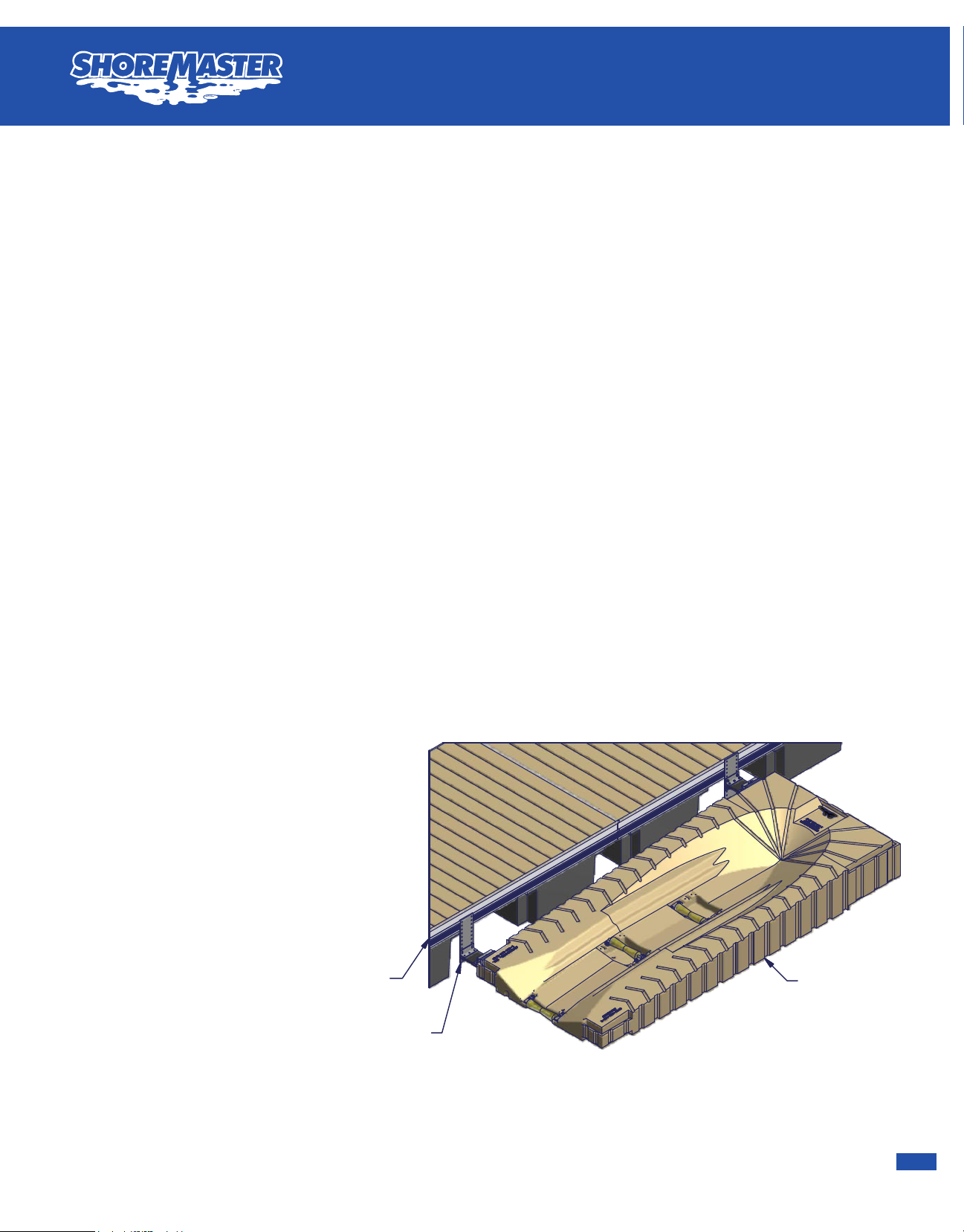
Failure to follow instructions may result in personal injury and may invalidate the applicable warranty.
Note: Refer to exploded parts drawing on following page for details on flexi hinge assembly.
Step 1. Attach flexi hinge assembly extension plate to floating dock. Plates will have to be spaced about 116-1/4" between
plates so they will line up to corresponding plates on the ShorePort. Attach brackets to ShorePort and measure between to
verify spacing.
Step 2. Assemble flexi hinge assembly. Slide connecting rod through hole in bottom of flexi hinge assembly weldment and
attach using oval screw (you will have to drill a pilot hole for screw). Next insert 5/16 x 4-1/2" hex bolt through lock washer,
rectangular washer and insert through hole in accessory top connector and thread into connector rod just enough to hold it
together. Attach rubber plate to flexi hinge assembly weldment using one flexi hinge assembly angle, three 3/8 x 2 hex bolts
and 3/8 nylock nuts. Attach two other flexi hinge assembly angles to other end of rubber plate using three 3/8 x 2 hex bolts and
3/8 nylock nuts (make sure to bolt through the holes not the slots).
Step 3. Attach previously assembled portion of flexi hinge assembly to front of ShorePort so the connecting rod will end up
centered in the second vertical groove on the front of the ShorePort and attach the rear side flexi-hinge to the rear side of the
ShorePort so its connector rod is centered in second groove from the back of the ShorePort. Leave connecting rod bolt loose.
Step 4. With no weight on the ShorePort float ShorePort next to floating dock and attach flexi hinge assembly extension plate
to flexi hinge assembly angles using four 3/8 x 1-1/4 hex bolts, flat washers and nylock nuts. Make sure ShorePort is floating
level in the water and rubber plate is level before attaching. After attached tighten all hardware. Torque 5/16" x 4-1/2" connector
rod bolts to 20 ft/lbs. DO NOT OVERTIGHTEN AND DO NOT USE A HIGH SPEED DRILL.
Kit includes front and back
brackets to attach side of
ShorePort to floating dock.
ShorePort Side Mount Flexi-Hinge
Instructions
Part #: 1013365
Note: If you are in an area with heavy boat traffic or
waves greater than 1'-6" use stand-off brackets
and pipe brackets instead of the flexi hinge
assembly. Side mount flexi-hinge assembly should
be used to attach only one ShorePort parallel to
dock. If multiple ShorePorts are to be attached side
by side pipe brackets should be used instead of
side mount flexi-hinge.
Side Mount Flexi-Hinge
®
®
Shoreport
SHOREMASTER.COM
Parts List
DESCRIPTIONQTY
ITEM
4' x 10' Floating Poly Dock21
ShorePort Front Connector
22
4' Poly Dock End Connector
13
Shoreport 1' Side Rear Connector
14
Shoreport
2
5
2' Notched Connector
16
Shoreport Rear Pipe Bracket with Hardware
2
7
The diagram below shows a typical ShorePort to poly dock installation. Before attaching ShorePorts to
dock make sure dock is anchored properly. Consult with your local dealer for anchoring requirements. If
needed you can attach ShorePorts rear pipe brackets to the back side of the ShorePorts. Remove the
bottom wear plate so the pile guide does not bind up on the pipe.
Note: Refer to Poly Dock installation instructions for connector instructions.
3
6
1
2
5
7
4
ShorePort to Poly Dock
Failure to follow instructions may
result in personal injury and may
invalidate the applicable warranty.
Step 1. Attach ShorePorts together
using 2' Notched Connector and
ShorePort 1' Side Rear Connector.
Step 2. Attach ShorePort to Poly Dock
using ShorePort front connectors.
Step 3. Slide 2" schedule 40 pipe into
pipe brackets and drive into ground
using post pounder.
DETAIL U
SCALE 1/35
U
ShorePort
Floating
Dock
Failure to follow instructions may result in personal injury and may invalidate the applicable warranty.
Note: Refer to exploded parts drawing on following page for details on flexi hinge assembly.
Step 1. Attach flexi hinge assembly extension plate to floating dock. Plates will have to be spaced about 116-1/4" between
plates so they will line up to corresponding plates on the ShorePort. Attach brackets to ShorePort and measure between to
verify spacing.
Step 2. Assemble flexi hinge assembly. Slide connecting rod through hole in bottom of flexi hinge assembly weldment and
attach using oval screw (you will have to drill a pilot hole for screw). Next insert 5/16 x 4-1/2" hex bolt through lock washer,
rectangular washer and insert through hole in accessory top connector and thread into connector rod just enough to hold it
together. Attach rubber plate to flexi hinge assembly weldment using one flexi hinge assembly angle, three 3/8 x 2 hex bolts
and 3/8 nylock nuts. Attach two other flexi hinge assembly angles to other end of rubber plate using three 3/8 x 2 hex bolts and
3/8 nylock nuts (make sure to bolt through the holes not the slots).
Step 3. Attach previously assembled portion of flexi hinge assembly to front of ShorePort so the connecting rod will end up
centered in the second vertical groove on the front of the ShorePort and attach the rear side flexi-hinge to the rear side of the
ShorePort so its connector rod is centered in second groove from the back of the ShorePort. Leave connecting rod bolt loose.
Step 4. With no weight on the ShorePort float ShorePort next to floating dock and attach flexi hinge assembly extension plate
to flexi hinge assembly angles using four 3/8 x 1-1/4 hex bolts, flat washers and nylock nuts. Make sure ShorePort is floating
level in the water and rubber plate is level before attaching. After attached tighten all hardware. Torque 5/16" x 4-1/2" connector
rod bolts to 20 ft/lbs. DO NOT OVERTIGHTEN AND DO NOT USE A HIGH SPEED DRILL.
Kit includes front and back
brackets to attach side of
ShorePort to floating dock.
ShorePort Side Mount Flexi-Hinge
Instructions
Part #: 1013365
Note: If you are in an area with heavy boat traffic or
waves greater than 1'-6" use stand-off brackets
and pipe brackets instead of the flexi hinge
assembly. Side mount flexi-hinge assembly should
be used to attach only one ShorePort parallel to
dock. If multiple ShorePorts are to be attached side
by side pipe brackets should be used instead of
side mount flexi-hinge.
Side Mount Flexi-Hinge

® ®
Shoreport
SHOREMASTER.COM
Parts List
DESCRIPTIONQTY
ITEM
4' x 10' Floating Poly Dock11
ShorePort
12
Large Pipe Bracket wtih Connector
13
Poly Pipe Bracket / ShorePort Side Connector
1
4
Shoreport Rear Pipe Bracket with Hardware
1
5
2" Schedule 40 Pipe
26
ShorePort Parallel to Poly Dock
Failure to follow instructions may
result in personal injury and may
invalidate the applicable warranty.
Step 1. Attach ShorePort to Poly Dock
using poly pipe bracket / ShorePort side
connector.
Step 2. Attach poly pipe bracket to
ShorePort.
Step 3. Slide 2" schedule 40 pipe into
pipe brackets and drive into ground using
post pounder.
Note: DO NOT attach ShorePort to Poly
Dock using only poly pipe bracket /
ShorePort side connector you must also
use a pipe bracket on the outside of the
ShorePort (as shown).
1
4
6
3
2
5
6
Note: See Connector Instructions for directions on how to
assemble ShorePort connectors.
DETAIL A
H
Parts List
DESCRIPTIONQTY
ITEM
ShorePort
11
Universal Stand-off Plate Assembly (Pair)
12
2" Schedule 40 Pipe
23
Shoreport Rear Pipe Bracket with Hardware
1
4
Medium Pipe Bracket with Hardware1
5
Standing Dock or Sea Wall
16
Parts List
DESCRIPTIONQTY
ITEM
ShorePort
11
2" schedule 40 PIPE22
Standing Dock or Sea Wall
13
Universal Stand-off Plate Assembly (Pair)
14
Large Pipe Bracket wtih Connector
2
5
A
1
4
2
3
6
ShorePort to Standing Dock or Sea Wall
Failure to follow instructions may result in personal
injury and may invalidate the applicable warranty.
Step 1. Attach pipe brackets to ShorePort (as shown)
depending on how you want your ShorePort fastened to your
dock or sea wall.
Step 2. Assemble and attach stand-off brackets to dock or
sea wall. If ShorePort is perpendicular to dock (as shown in
top picture) assemble stand-off brackets using last four holes
in plates so brackets will hold pipes further away from dock.
Measure from center of pipe bracket to the center of the other
pipe bracket and space stand-off brackets apart center to
center to that distance. If ShorePort is parallel to dock (as
shown in middle picture) assemble stand-off brackets so they
are as short as possible to keep ShorePort closer to the dock.
Measure from center of pipe bracket to the center of the other
pipe bracket and space stand-off brackets apart center to
center to that distance.
Step 3. Float ShorePort up next to dock and slide pipe down
through pipe brackets. Align pipe up with stand-off brackets
and pound pipe into lake bottom using a sledge hammer or
post pounder.
Step 4. Attach pipe to stand-off brackets using provided
U-bolts.
Note: If your dock is too close to the water bolt the stand-off
brackets to a treated 2" x 8" and bolt the 2" x 8" to the dock
(as shown in Detail A).
1
5
3
4
5
2
Treated 2" x 8"

®
®
Shoreport
SHOREMASTER.COM
Parts List
DESCRIPTIONQTY
ITEM
4' x 10' Floating Poly Dock11
ShorePort
12
Large Pipe Bracket wtih Connector
13
Poly Pipe Bracket / ShorePort Side Connector
1
4
Shoreport Rear Pipe Bracket with Hardware
1
5
2" Schedule 40 Pipe
26
ShorePort Parallel to Poly Dock
Failure to follow instructions may
result in personal injury and may
invalidate the applicable warranty.
Step 1. Attach ShorePort to Poly Dock
using poly pipe bracket / ShorePort side
connector.
Step 2. Attach poly pipe bracket to
ShorePort.
Step 3. Slide 2" schedule 40 pipe into
pipe brackets and drive into ground using
post pounder.
Note: DO NOT attach ShorePort to Poly
Dock using only poly pipe bracket /
ShorePort side connector you must also
use a pipe bracket on the outside of the
ShorePort (as shown).
1
4
6
3
2
5
6
Note: See Connector Instructions for directions on how to
assemble ShorePort connectors.
DETAIL A
H
Parts List
DESCRIPTIONQTY
ITEM
ShorePort
11
Universal Stand-off Plate Assembly (Pair)
12
2" Schedule 40 Pipe
23
Shoreport Rear Pipe Bracket with Hardware
1
4
Medium Pipe Bracket with Hardware1
5
Standing Dock or Sea Wall
16
Parts List
DESCRIPTIONQTY
ITEM
ShorePort
11
2" schedule 40 PIPE22
Standing Dock or Sea Wall
13
Universal Stand-off Plate Assembly (Pair)
14
Large Pipe Bracket wtih Connector
2
5
A
1
4
2
3
6
ShorePort to Standing Dock or Sea Wall
Failure to follow instructions may result in personal
injury and may invalidate the applicable warranty.
Step 1. Attach pipe brackets to ShorePort (as shown)
depending on how you want your ShorePort fastened to your
dock or sea wall.
Step 2. Assemble and attach stand-off brackets to dock or
sea wall. If ShorePort is perpendicular to dock (as shown in
top picture) assemble stand-off brackets using last four holes
in plates so brackets will hold pipes further away from dock.
Measure from center of pipe bracket to the center of the other
pipe bracket and space stand-off brackets apart center to
center to that distance. If ShorePort is parallel to dock (as
shown in middle picture) assemble stand-off brackets so they
are as short as possible to keep ShorePort closer to the dock.
Measure from center of pipe bracket to the center of the other
pipe bracket and space stand-off brackets apart center to
center to that distance.
Step 3. Float ShorePort up next to dock and slide pipe down
through pipe brackets. Align pipe up with stand-off brackets
and pound pipe into lake bottom using a sledge hammer or
post pounder.
Step 4. Attach pipe to stand-off brackets using provided
U-bolts.
Note: If your dock is too close to the water bolt the stand-off
brackets to a treated 2" x 8" and bolt the 2" x 8" to the dock
(as shown in Detail A).
1
5
3
4
5
2
Treated 2" x 8"
This manual suits for next models
1
Other Shoremaster Lifting System manuals


Popular Lifting System manuals by other brands


Ergoswiss
Ergoswiss SLA 13 Series Operating instruction

Aqua Creek
Aqua Creek F-03EZPL Installation, assembly and operating instructions

PRO LIFTS
PRO LIFTS VMB TL-A300 Operating instructions & user manual

Bend-Pak
Bend-Pak HDS-37 Installation and operation manual

Stage right
Stage right AlphaRoll Series Product information packet

U.S. General
U.S. General 91960 Assembly and operating instructions


