manuals.online logo
Brands
  1. Home
  2. •
  3. Brands
  4. •
  5. ShoreStation
  6. •
  7. Lifting System
  8. •
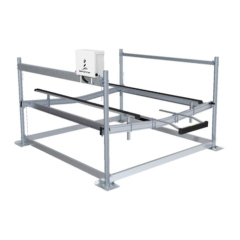
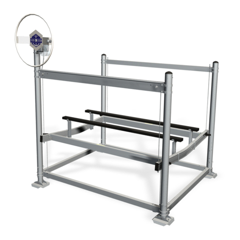
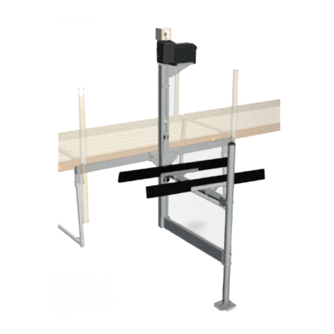
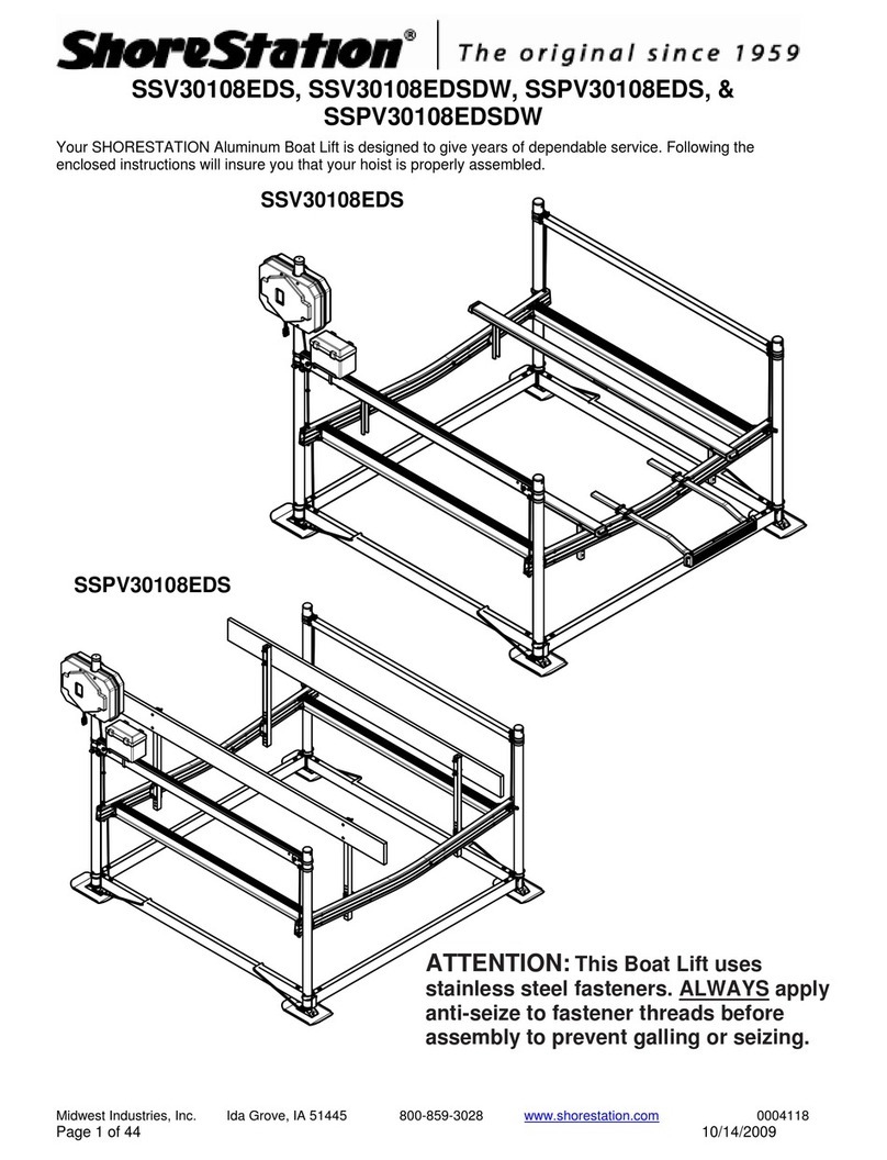
  9. ShoreStation SSV40108HS User manual

ShoreStation SSV40108HS User manual

Midwest Industries, Inc. Ida Grove, IA 51445 800-859-3028 www.shorestation.com 0004205
Page 1 of 22 Rev 2.7 3/13/2018
Assembly Instructions
Hydraulic Boat Lift
SSV40108HS & HSDW, SSV40120HS & HSDW, SSV50120HS,
SSPV50132LHS, SSPV60120LHS, & SSV60120HS & HSDW,
SSV60132HS, SSV80132HSDW, SSV100132HSDW &
SSPV100144HSDW, SSV100144HSDW, & SSV150144HSDW
Midwest Industries, Inc. Ida Grove, IA 51445 800-859-3028 www.shorestation.com 0004205
Page 2 of 22 Rev 2.7 3/13/2018
Step #1 –Sort Hardware
Open the hardware box and bag and sort the hardware and other contents by size. Locate the
fastener finder sheet in the hardware box to help identify the fasteners used in the assembly of
these lifts.
Step #2 –Assemble Base Pads
Collect enough of the fasteners and items shown below to assemble four base pads. Align the
channel clamp with the holes in the base pad as shown, insert bolts from the bottom up and
secure with lock nuts. Tighten and repeat for all four base pads.
Midwest Industries, Inc. Ida Grove, IA 51445 800-859-3028 www.shorestation.com 0004205
Page 3 of 22 Rev 2.7 3/13/2018
Step #3 –Assemble Base Pads to Legs
Locate the leg bundle or bundles and cut the bands to open it up. Locate bolts and nuts in the
pre-packaged bag and slide the bolt thru the channel clamp and the adjustable leg tube as
shown and secure with a brass locknut with nylon insert.
Note that the bolts (1/2-13 X 4 1/2” HC Stainless and Brass lock nut with nylon insert) should
be inserted in the same direction as that of the u-bolt. Repeat this process on the remaining
legs.
Midwest Industries, Inc. Ida Grove, IA 51445 800-859-3028 www.shorestation.com 0004205
Page 4 of 22 Rev 2.7 3/13/2018
Step #4 –Assembly of Lower Side Frame
Using the chart at the bottom of the page find the model that you are assembling, locate the
necessary components that are included in the lower frame bundle. Your assembly will start by
laying two legs down with the corner blocks as shown and using the chart slide a sideframe
tube over the corner block and insert the short bolt (see chart) with a 3/8” flat washer into the
hole closest to the post assembly. Secure with flat washer and brass locknut. DO NOT
TIGHTEN.
Midwest Industries, Inc. Ida Grove, IA 51445 800-859-3028 www.shorestation.com 0004205
Page 5 of 22 Rev 2.7 3/13/2018
LOWER FRAME SSPV60120LHS
Front & Rear
Crossmembers
Side frames Short Bolts
Long Bolts
SSV40108HS &
HSDW
5" X 2" X 107" 5" X 2" X 131" 3/8-16 X 6" 3/8-16 X 6 1/2"
SSV40120HS &
HSDW, SSV50120HS
5" X 2" X 119" 5" X 2" X 131" 3/8-16 X 6" 3/8-16 X 6 1/2"
SSPV50132LHS 5" X 2" X 131" 5" X 2" X 167" 3/8-16 X 6" 3/8-16 X 6 1/2"
SSPV60120LHS 6" X 2" X 119" 6" X 2" X 167" 3/8-16 X 7" 3/8-16 X 7 1/2"
SSV60120HS &
HSDW
6" X 2" X 119" 6" X 2" X 143" 3/8-16 X 7" 3/8-16 X 7 1/2"
SSV60132HS 6" X 2" X 131" 6" X 2" X 143" 3/8-16 X7" 3/8-16 X 7 1/2"
SSV80132HSDW 6" X 2" X 131" 6" X 2" X 155" 3/8-16 X 7" 3/8-16 X 7 1/2"
SSV10132HSDW 6" X 2" X 131" 6" X 2" X 155" 3/8-16 X 7" 3/8-16 X 7 1/2"
SSPV100144HSDW 8" X 2" X 143" 8" X 2" X 155" 3/8-16 X 8 1/2" 3/8-16 X 9"
SSV150144HSDW 8" X 2" X 143" 8" X 2" X 185" 3/8-16 X 8 1/2" 3/8-16 X 9"
Lower Frame Components
Bolts to Assemble
Midwest Industries, Inc. Ida Grove, IA 51445 800-859-3028 www.shorestation.com 0004205
Page 6 of 22 Rev 2.7 3/13/2018
Step #5 –Attach Front & Rear Frame Crossmembers
Using the chart, locate the correct length tubes for crossmembers. With the unit still laying on
it’s side, slide the crossmembers over the other corner block leg and insert the short bolt with a
washer into the hole closest to the post and secure on the bottom with a flat washer and brass
lock nut. DO NOT TIGHTEN.
Step #6 –Complete Frame Corner Assembly
Flip the entire assembly upright onto the base pads.
Locate the long bolts and the bottom corner cable bracket. Insert the long bolt with a flat
washer thru the second hole from the post, thru the frame tubes and then thru the corner cable
bracket on the bottom as shown. Secure with a flat washer and brass lock nut. Do not tighten.
Note: The leg bundle for the
SSV150144HSDW has stops welded to
the leg tubes and should be used at this
time.
Midwest Industries, Inc. Ida Grove, IA 51445 800-859-3028 www.shorestation.com 0004205
Page 7 of 22 Rev 2.7 3/13/2018
Step #7 –Complete Bottom Frame & Post Assembly
Insert the corner blocks of the two remaining leg assemblies into the crossmembers as shown
below, insert short bolts with washers in the holes closest to the posts to keep them in place.
Pull the legs apart slightly and slide the other side frame over the corner blocks and secure
these also with short bolts, washers, and brass lock nuts. Square the frame and tighten all
hardware installed.
Properly Securing a Lift’s Lower Frame
Tighten all fasteners with an air or battery powered high torque impact wrench. It’s important
to tighten the fasteners so the platform tube pulls tight to the corner block. The fastener needs
to slightly crease the tube wall until there is no gap between the tube and the corner block. In
some instances the impact wrench may not have enough torque and it may be necessary to
hand tighten in order to achieve contact with the corner block.
Midwest Industries, Inc. Ida Grove, IA 51445 800-859-3028 www.shorestation.com 0004205
Page 8 of 22 Rev 2.7 3/13/2018
Step #8A –Assemble the Lift Platform for 4000#, 5000#, and 6000#
Lay the V-Shaped cradle tubes across the lower frame as shown (4000, 5000, and 6000lb).
Place the end with the lift cable threaded out the bottom on the same side as the corner cable
brackets.
For the 4000, 5000, and 6000 lb. models insert a carriage bolt into the corner guide as shown
and slide the head into the top slot in the cradle tube. Secure corner guide with a flat washer
and lock nut. Do the same on the other three corners. Slide two carriage bolts into the top slot
Midwest Industries, Inc. Ida Grove, IA 51445 800-859-3028 www.shorestation.com 0004205
Page 9 of 22 Rev 2.7 3/13/2018
and 2 into the bottom slot on the inside of the cradle tube. Using those bolts, mount a pair of
side rail brackets on each end of the cradle tube as shown above. Position the outer edge of
the brackets at least 3 inches from the end of the cradle tube. It is important to keep this
distance equal on all four corners to keep it square. Do not tighten at this time.
Insert the platform rails into the space between the mounting brackets and between the v-
frames and secure with bolts, washers and nuts as shown.
Step #8B –Assemble the Lift Platform for 8000# - 15000#
The cradle tubes on all the lifts above 8000# have galvanized steel cradle tubes with different
attaching system. They also use the plastic (plastic and aluminum) ring style corner guides.
Lay the galvanized cradle tubes on the bottom frame with the end with the cables coming out
the bottom on the same side as the corner cable brackets. Slide the corner guides over the
post and attach as shown.
Place the platform side rails between the welded brackets on the cradle tube and attach as
illustrated above (use the same fasteners as used for the aluminum cradle tube on the 4000# -
6000# lifts illustrated above).
Midwest Industries, Inc. Ida Grove, IA 51445 800-859-3028 www.shorestation.com 0004205
Page 10 of 22 Rev 2.7 3/13/2018
The following picture shows the position of the level cable as it comes over the pulley in the
cradle tube and out the bottom to go to the cable mounting bar attached to the corner of the
lower frame. Note the other two holes on the end of the cradle tube. These will be used later to
attach the cables coming from the bottom of the lift tube.
Step #9 –Attach the Level Cable
Attach the level cable as shown inserting the cable into the hole closest to the sideframe and
securing with a flat washer and 2 brass hex nuts (see chart on page 12 for hardware sizes).
The first nut will be run to the bottom of the threads and the second run down and secured
tightly against the first. Repeat on other level cable.
Midwest Industries, Inc. Ida Grove, IA 51445 800-859-3028 www.shorestation.com 0004205
Page 11 of 22 Rev 2.7 3/13/2018
Step #10 –Install the Side Spacer Brace Tube
The side spacer brace tube is located opposite the lift tube so install it on the posts opposite
the corner cable brackets. The 4000#, 5000#, & 6000# lifts use a drop side brace tube and the
8000# thru 15000# lifts use a straight side brace tube. Locate the appropriate brackets and
hardware from the illustrations below. Mount the spacer tube to the post as shown, keeping the
lock nuts on the outside. Adjust brackets on both sides to the height indicated by the chart on
page 14 and tighten all fasteners securely.
4000# - 5000# - 6000#
8000# - 15,000#
Midwest Industries, Inc. Ida Grove, IA 51445 800-859-3028 www.shorestation.com 0004205
Page 12 of 22 Rev 2.7 3/13/2018
Step # 11 –Attach Level Cables to Spacer Brace Tube
Insert the ends of the level cables (from the cradle tubes) directly up thru the space brace tube
and secure with hardware from chart below. Hint: Block the platform off the lower frame about
6 inches to create enough slack for the cable to pass thru the brace tube.
4000# - 5000# - 6000# 8,000# - 15,000#
Hoist Models
Hex Nut Washers Hex Nuts Washers
SSV40108HS & HSDW 5/8-11 5/8 5/8-11 5/8
SSV40120HS & HSWD,
SSV50120HS
5/8-11 5/8 5/8-11 5/8
SSPV50132LHS 5/8-11 5/8 5/8-11 5/8
SSPV60120LHS &
SSV60120HS &HSDW
5/8-11 5/8 5/8-11 5/8
SSV60132HS 5/8-11 5/8 5/8-11 5/8
SSV80132HSDW 5/8-11 5/8 & A314* 5/8-11 5/8
SSV100132HSDW 5/8-11 5/8 & A314* 7/8-9 7/8
SSPV100144HSDW 5/8-11 5/8 & A314* 7/8-9
SSV150144HSDW 7/8-9 7/8 & 6767900* 1 1/8-7
Level Cable
Lift Cables
Step #12 –Install the Hydraulic Lift Tube/Assemblies
The lift tube contains the hydraulic cylinder and is quite heavy. You will need several people or
powered assist to lift and hold it in position until it is secured. Orient the lift tube on the side of
the lift with the corner cable brackets, the cables exiting the bottom and hydraulic ports to the
outside. Locate the brackets and hardware for your model as specified below. Locate the
Midwest Industries, Inc. Ida Grove, IA 51445 800-859-3028 www.shorestation.com 0004205
Page 13 of 22 Rev 2.7 3/13/2018
brackets at the height indicated on the chart on page 14 and attach the hydraulic lift tube as
shown. Tighten all fasteners securely
4,000# - 6,000# 8,000#
10,000# & 15,000#
On the fully assembled lift assemblies
for the 10,000# and the 15,000# you
will need to loosen the 1/2" lock nuts on
the plates (DO NOT REMOVE ANY OF
THE 1/2” BOLTS OR LOCK NUTS)
which hold the assembly together. This
will allow it to slide down over the
corner post to get it in position at the
according to measurements on the
chart on page 14 or on the stops. Once
in place complete assembly using
shown hardware and tighten securely.
Midwest Industries, Inc. Ida Grove, IA 51445 800-859-3028 www.shorestation.com 0004205
Page 14 of 22 Rev 2.7 3/13/2018
Lift Assembly Measurements
The following table shows the lift tube and brace tube (drop side) measurements for each lift model. Find the lift model in
the table and place the components as shown in the diagrams. Tighten all components according to the assembly
instructions after properly locating the lift tubes.
Lift Tube
Height (X)
Brace Tube
Height (Y)
SSV1564ED
69”
69”
SSV1564M
69”
69”
SSV20100EDS
69-1/4”
69-1/4”
SSV20100MS
69-1/4”
69-1/4”
SSV30108EDS
68”
68”
SSV30108MS
68”
68”
SSV30120EDS
68”
68”
SSV30120MS
68”
68”
SSV40108EDS
68”
68”
SSV40108HS
71-1/2”
75-1/2”
SSV40108MS
68”
68”
SSV40120EDS
68”
68”
SSV40120HS
71-1/2”
75-1/2”
SSV40120MS
68”
68”
SSV50108EDS
76”
76”
SSV50108MS
76”
76”
SSV50120EDS
76”
76”
SSV50120HS
71-1/2”
75-1/2”
SSV50120MS
76”
76”
SSV60108EDS
78”
77-1/2”
SSV60120EDS
78”
77-1/2”
SSV60120HS
80”
75-1/2”
SSV60132HS
80”
75-1/2”
SSV70120HSDW
80”
87”
SSV70132HSDW
80”
87”
SSV80132HSDW
87”
87”
SSPV50132LEDS
76”
76”
SSPV50132LHS
71-1/2”
76-3/4””
SSPV50132MLS
76”
76”
SSV100132HSDW
95”
87”
SSV100144HSDW
97”
90-1/2”
SSV150144HSDW
109”
102”
X
Y
Note: The lift measurements can vary up to 1 ½” due to
cable length variation. Adjust the placement to ensure the
platform is level and the lift cables can reach the cradle
attachment.
Midwest Industries, Inc. Ida Grove, IA 51445 800-859-3028 www.shorestation.com 0004205
Page 15 of 22 Rev 2.7 3/13/2018
Step #13 –Mounting the Pump Box
Refer to instructions included in the pump box. Place battery in box and place inside pump
box. Attach red battery cable to the positive post and black to negative post. This would also
be the time to attach the short Battery Tender harness to the battery matching the colored
cable ends to the battery cables. Do not allow the cables to make contact with each other
or any part of the lift.
Midwest Industries, Inc. Ida Grove, IA 51445 800-859-3028 www.shorestation.com 0004205
Page 16 of 22 Rev 2.7 3/13/2018
Step #14 Connecting Battery to 12
Volt Pump
The positive and negative cables
from the battery will be mounted as
shown for 12 volt pumps..
Step #14A –Connecting the Battery Cables 24-Volt Pump
The long black ground cable will be connected to the negative post. The short black cable will
be used to hook the batteries together
positive on one battery to the negative on
the other. The red battery cable will be
hooked to the positive on the battery.
Connect the battery cable from the battery
bank to the motor battery cable.
Midwest Industries, Inc. Ida Grove, IA 51445 800-859-3028 www.shorestation.com 0004205
Page 17 of 22 Rev 2.7 3/13/2018
Step #15 –Dockside Control Box w/Lockout
With the pump and battery mounted it will be time to mount the dockside control box and 35
foot cord unit to the post on the dock side of the lift. The cord will be routed thru the canopy
and attached to the hoop with zip ties or use the underwater conduit kit to run it along the
frame under water..
Open the hose clamps and insert the ends thru the slots in the controller bracket, place on the
leg post next to the dock reconnect the hose clamp and secure. Plug the connector to the one
mounted to the pump. At this time program or check the remotes (refer to the Quick Start
Hydraulic Controller instructions included in the pump box for key fob programming and
operation) to be sure they will operate the system.
Midwest Industries, Inc. Ida Grove, IA 51445 800-859-3028 www.shorestation.com 0004205
Page 18 of 22 Rev 2.7 3/13/2018
Step #16 –Connecting Lift Tube Cables
Using the Key Fob remote controller, push the Down Button to run the cables down so they
can be attached to the lift platform.
Attaching cables to Aluminum Cradle Tubes: the cable coming from the outside pulley of
the Lift Tube goes thru the outside holes in the Cradle Tube. The cable coming from the
inside pulley, on the other end of the Lift Tube, goes thru the inside hole on the Cradle
Tube.
Attaching cables to Steel Cradle Tubes: both cables are attached to the cable mounting
brackets welded into the end of the steel Cradle Tube.
Secure the cables to the Cradle Tubes with 2 brass nuts and a flat washer as shown below.
Refer to the chart on page 11 for the proper sizes.
4000# - 6000# Aluminum
8,000# - 15,000# Steel
Midwest Industries, Inc. Ida Grove, IA 51445 800-859-3028 www.shorestation.com 0004205
Page 19 of 22 Rev 2.7 3/13/2018
Step #17 –Attaching Upper Limit Switch
Attach the upper limit switch to the bottom of the winch tube assembly as shown. The holes
will allow the switch to be adjusted so the cable will travel thru the center of the slot in the pivot
arm. The two halves of the bump stop will be mounted to the cable with carriage bolts and kep
nuts, the final placement will not be made until the lift is in the water and the boat can be
loaded into the lift.
Midwest Industries, Inc. Ida Grove, IA 51445 800-859-3028 www.shorestation.com 0004205
Page 20 of 22 Rev 2.7 3/13/2018
Step #18A –Mounting the Battery Tender
Models: HA0083 (12V), HA0084 (24V)
The Battery Tender battery charger is to be plugged into a properly and safely installed 110
volt power line near the lift. It is designed to rapidly re-charge the battery then maintain a full
charge. The Battery Tender Kit included with this lift contains the charger unit with power cord,
short battery harness and 25 ft. long connecting cord. For additional operating and safety
instructions, please see the Battery Tender Instruction Manual packed with this kit. Mount the
charger unit according to instructions included with the kit
Step #18B –Boat Lift Solar Charger
Models: HA0110 (12V), HA0135 (24V)
The ShoreStation Boat lift solar chargers are
Specifically designed to provide reliable, trouble-free
charging and maintenance of your ShoreStation
lift battery. Proper installation of this charging system
will maximize your charger’s performance and will
ensure your battery maintains a sufficient charge for
your lift system.

This manual suits for next models

14

Other ShoreStation Lifting System manuals

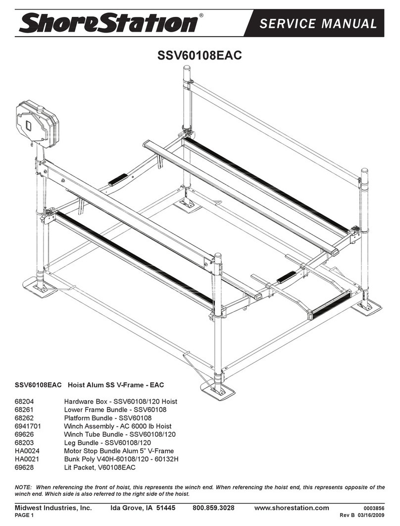
ShoreStation SSV60108EAC User manual

ShoreStation

ShoreStation SSV60108EAC User manual

ShoreStation SSV30108EAC User manual

ShoreStation

ShoreStation SSV30108EAC User manual

ShoreStation FlexPower SSV30108EDS User manual

ShoreStation

ShoreStation FlexPower SSV30108EDS User manual

ShoreStation SSV40120EDC User manual

ShoreStation

ShoreStation SSV40120EDC User manual

ShoreStation SSV20100EDC User manual

ShoreStation

ShoreStation SSV20100EDC User manual

ShoreStation WATERFRONT SYSTEMS User manual
ShoreStation

ShoreStation WATERFRONT SYSTEMS User manual

ShoreStation Manual SSV50108MS User manual

ShoreStation

ShoreStation Manual SSV50108MS User manual

ShoreStation SSV1564M User manual

ShoreStation

ShoreStation SSV1564M User manual

ShoreStation Manual SSV50108MS User manual

ShoreStation

ShoreStation Manual SSV50108MS User manual

ShoreStation SSV40120EAC User manual

ShoreStation

ShoreStation SSV40120EAC User manual

ShoreStation SSV60108MS User manual

ShoreStation

ShoreStation SSV60108MS User manual

ShoreStation Manual SSV20100MS User manual

ShoreStation

ShoreStation Manual SSV20100MS User manual

ShoreStation Manual SSV40120MS User manual

ShoreStation

ShoreStation Manual SSV40120MS User manual

ShoreStation SS1053DE User manual

ShoreStation

ShoreStation SS1053DE User manual

ShoreStation SSV40120EAS User manual

ShoreStation

ShoreStation SSV40120EAS User manual

ShoreStation SSV15100EDC User manual

ShoreStation

ShoreStation SSV15100EDC User manual

ShoreStation SS1053 User manual

ShoreStation

ShoreStation SS1053 User manual

ShoreStation SSV60120EDC User manual

ShoreStation

ShoreStation SSV60120EDC User manual

ShoreStation FlexPower SSV30120EDS User manual

ShoreStation

ShoreStation FlexPower SSV30120EDS User manual

ShoreStation FlexPower SSV40120EDS User manual
ShoreStation

ShoreStation FlexPower SSV40120EDS User manual

ShoreStation SSV30120EDC User manual

ShoreStation

ShoreStation SSV30120EDC User manual

ShoreStation SSV40108HAC User manual

ShoreStation

ShoreStation SSV40108HAC User manual

ShoreStation SSV30108EDC User manual

ShoreStation

ShoreStation SSV30108EDC User manual

ShoreStation SSV30120EAS User manual

ShoreStation

ShoreStation SSV30120EAS User manual

Popular Lifting System manuals by other brands

ARJO HUNTLEIGH KWIKtrak Assembling instructions

ARJO HUNTLEIGH

ARJO HUNTLEIGH KWIKtrak Assembling instructions

MAHLE CML-7 Operation manual

MAHLE

MAHLE CML-7 Operation manual

morse 510-125 Operator's manual

morse

morse 510-125 Operator's manual

Terrier TVK owner's manual

Terrier

Terrier TVK owner's manual

pewag BLCW owner's manual

pewag

pewag BLCW owner's manual

OMA 503 manual

OMA

OMA 503 manual

Liko Uno 200 Service manual

Liko

Liko Uno 200 Service manual

AMGO Hydraulics PRO-12SX Installation and service manual

AMGO Hydraulics

AMGO Hydraulics PRO-12SX Installation and service manual

Summit 908300GA owner's manual

Summit

Summit 908300GA owner's manual

HMS-VILGO LIFTY 4 user guide

HMS-VILGO

HMS-VILGO LIFTY 4 user guide

Kessel 28743 installation manual

Kessel

Kessel 28743 installation manual

Scaleo medical Poweo 300 user manual

Scaleo medical

Scaleo medical Poweo 300 user manual

Genie GS-1530 Maintenance manual

Genie

Genie GS-1530 Maintenance manual

MARTINS Industries MTWL user manual

MARTINS Industries

MARTINS Industries MTWL user manual

Strongway 55833 owner's manual

Strongway

Strongway 55833 owner's manual

TBM TB1104 instruction manual

TBM

TBM TB1104 instruction manual

BorMann BWR5119 Assembly and operation instructions

BorMann

BorMann BWR5119 Assembly and operation instructions

EKKO EB12EA Series manual

EKKO

EKKO EB12EA Series manual

manuals.online logo
manuals.online logoBrands
  • About & Mission
  • Contact us
  • Privacy Policy
  • Terms and Conditions

Copyright 2025 Manuals.Online. All Rights Reserved.