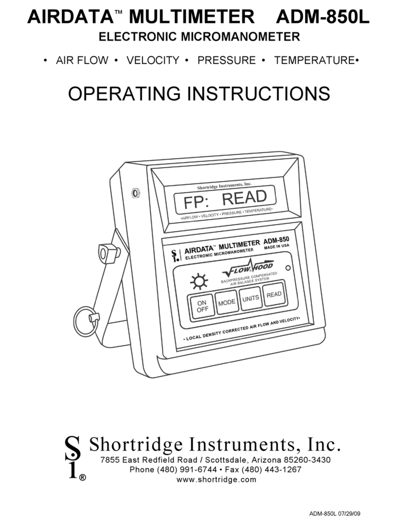
Shortridge Instruments FLOWHOOD AIRDATA CFM-88 User manual

CFM-88L 07/20/09
Shortridge Instruments, Inc.
7855 East Redfield Road / Scottsdale, Arizona 85260-3430
Phone (480) 991-6744 • Fax (480) 443-1267
www.shortridge.com
S
i®
CFM-88L
BACKPRESSURE COMPENSATED AIR BALANCE SYSTEM
OPERATING INSTRUCTIONS

CFM-88L 07/20/09i
CONTENTS
1.0 INTRODUCTION 1
1.1 GENERAL DISCUSSION 1
2.0 SPECIFICATIONS 2
3.0 EXTERNAL FEATURES 3
3.1 KEYPAD 3
3.2 FEATURES ON SIDES AND BACK OF METER 3
4.0 DISPLAY MESSAGES AND PROMPTS 5
4.1 READ PROMPTS 5
4.2 MEASUREMENT READOUTS 5
4.3 FUNCTION READOUTS 5
5.0 USING THE AIRDATA FLOWMETER 9
5.1 GENERAL USE 9
5.2 TREND READINGS 9
6.0 TEMPERATURE MEASUREMENT 10
6.1 TEMPROBE 10
6.2 AIRDATA MULTITEMP 10
7.0 ABSOLUTE PRESSURE 12
8.0 AIR FLOW MEASUREMENT 13
8.1 FLOWHOOD FUNCTION 13
8.2 BACKPRESSURE COMPENSATION 13
9.0 FLOWHOOD ASSEMBLY 14
9.1 UNPACKING 14
9.2 FRAME ASSEMBLIES 14
9.3 FABRIC TOPS 14
9.4 TOP SUPPORT ASSEMBLY 14
9.5 HANDLE 15
10.0 FLOWHOOD OPERATING PROCEDURE 20
10.1 AIR FLOW - NONBACKPRESSURE COMPENSATED READINGS 20
10.2 AIR FLOW - BACKPRESSURE COMPENSATED READINGS 20
10.2.1 RATIO ERR DISPLAY 21
11.0 SPECIAL BALANCING PROCEDURES 22
11.1 PROPORTIONAL BALANCING 22
11.2 LARGE RETURN AIR GRILLES 22
11.3 KITCHEN EXHAUST HOODS 22
11.4 CONSTANT VOLUME CONTROLLERS 22
11.5 LINEAR SLOT DIFFUSERS 22
11.6 SIDEWALL REGISTERS 22
11.7 14"x14"x14" SHORT TOP SET 23
11.8 SYSTEM PROBLEMS 23
12.0 CORRECTION FACTORS AND CONVERSION FORMULAS 24
12.1 BAROMETRIC PRESSURE DENSITY CORRECTION - LOCAL DENSITY 24
12.2 BAROMETRIC PRESSURE DENSITY CONVERSION - STANDARD DENSITY 24
12.2.1 STANDARD DENSITY - TEMPROBE USED 24
12.2.2 STANDARD DENSITY - TEMPROBE NOT USED 24
12.3 TEMPERATURE DENSITY CORRECTION 24
12.4 RELATIVE HUMIDITY CORRECTION 24
13.0 METER ACCURACY FIELD TESTING 25
13.1 METER ZERO FUNCTION 25
13.2 ABSOLUTE PRESSURE FUNCTION 25
13.3 AIR FLOW ACCURACY 25
13.4 DUCT TRAVERSE COMPARISONS - INCLINED MANOMETER OR MICROMANOMETER 25

CFM-88L 07/20/09ii
13.5 DUCT TRAVERSE USING THE AIRDATA MULTIMETER 26
13.6 BACKPRESSURE COMPENSATED COMPARISON READING 26
13.7 NONBACKPRESSURE COMPENSATED COMPARISON READING 26
14.0 METER MAINTENANCE 27
15.0 FLOWHOOD MAINTENANCE 27
16.0 RECALIBRATION AND REPAIR INFORMATION 28
AIR BALANCE MANUALS & TRAINING PROGRAMS 28
WARRANTY 29
APPENDIX A - BATTERY TEST PROCEDURE 30
REPLACEMENT PARTS LIST 32
INDEX 34
Copyright © Shortridge Instruments, Inc., 2009. All rights reserved. This information may not be reproduced or duplicated in
any manner, or for any purpose, without permission in writing from Shortridge Instruments, Inc. Addendums or revisions
made to this manual after July 2009 may be found at www.shortridge.com.

CFM-88L 07/20/09iii
ILLUSTRATIONS
3.1 CFM-88L METER FRONT AND BACK 4
6.1 ADT442 TEMPROBE 10
6.2 AIRDATA MULTITEMP 11
9.1 FRAME STORAGE 16
9.2 FLOWHOOD IN CASE 16
9.3 FLOWHOOD ASSEMBLY 17
9.4 2X2 FRAME ASSEMBLY 18
9.5 1X4 FRAME ASSEMBLY 18
9.6 2X4 FRAME ASSEMBLY 18
9.7 1X5 FRAME ASSEMBLY 19
9.8 3X3 FRAME ASSEMBLY 19

CFM-88L 07/20/091
1.0 INTRODUCTION
1.1 GENERAL DISCUSSION
These instructions will be much easier to follow if the meter is in front of you as you read through them. You can note the
various connections and press the keys, observing the displayed results as you read through the various procedures. The
operation of the meter is quite simple and straightforward, as will become apparent after a little practice.
The CFM-88L AirData FlowMeter performs the following essential functions. When used with the Series 8400 FlowHood
Kit, this meter measures air flow and compensates for air density and backpressure effects, allowing direct air flow readings.
Temperature and absolute pressure measurements can be taken over a wide range.
The AirData FlowMeter and the AirData Multimeter automatically correct for air density variations due to local barometric
pressure. The meter also automatically corrects for the density effect of temperature if the TemProbe is connected. These
meters also may be used to compensate for the backpressure effect which occurs when any capture hood is placed over an
outlet. These capabilities eliminate several possible error factors, and the time consuming calculations normally necessary
to convert the air flow readings to local density results.
Internal calibration and zeroing of the AirData FlowMeter are fully automatic. No external adjustments are ever needed. This
instrument is extremely tolerant of overpressure, and is unaffected by position or ambient temperatures from 40/F to 140/F.
NOTE: The FlowHood may require the development and use of correction factors when used on swirl diffusers, or on other
types of diffusers with uneven air throw. The FlowHood may not be appropriate for use on small supply outlets at high jet
velocities or “nozzle” type outlets. These outlets cause an extreme concentration of air velocity on portions of the flow sensing
grid. The FlowHood readings may be inaccurate under such conditions.
Consideration must be given to other system components, such as may be encountered on some single supply air outlet
applications, where the FlowHood's slight backpressure may directly affect fan performance, or where the FlowHood's
backpressure correction function may be affected by immediate response from a volume control box or air valve.
It is recommended that the AirData FlowMeter be returned to the factory at least every two years for recalibration and software
update. This preventive maintenance program will assure that the original accuracy of the meter is maintained throughout
the life of the meter.

CFM-88L 07/20/092
2.0 SPECIFICATIONS
AIR FLOW: Measured in cubic feet per minute (cfm) or liters per second (L/s), corrected for local air density. This function
requires the use of the Shortridge Instruments' Series 8400 Backpressure Compensating FlowHood System. The
measurement range is 25 to 2500 cfm supply and 25 to 1500 cfm exhaust. Accuracy is ± 3% of reading ± 7 cfm
from 100 to 2000 cfm (nonbackpressure compensated readings).
ABSOLUTE PRESSURE: Measured in inches of mercury (in Hg) or bars with reference to a vacuum. The measurement
range is 10-40 in Hg. Maximum safe pressure is 60 psia. Accuracy is ± 2% of reading ± 0.1 in Hg from 14 to 40
in Hg.
TEMPERATURE: Accuracy is ± 0.5/F from 32/F to 158/F with a resolution of 0.1/F using the ADT442, ADT443, ADT444,
ADT445 or ADT446 TemProbes. Meter will display readings from -67.0/F to 250.0/F. Safe exposure range for
TemProbe is -100/F to 250/F. Do not expose the plastic base of the TemProbe or extension wand to temperatures
above 200/F.
AIR DENSITY CORRECTION: The air density correction range is 14-40 in Hg and 32/F to 158/F for correction of air flow
measurements. The readings represent local density air flow corrected for the density effects of temperature and
absolute pressure.
RESPONSE TIME: Varies from one second at higher pressure inputs to seven seconds at pressure inputs less than 0.0003
in wc. Extremely low flow inputs require longer sample times than higher flow inputs. TREND mode provides
continuous readings in less than two second intervals. (Accuracy specifications do not apply in TREND mode).
READOUT: Ten digit, 0.4 inch, liquid crystal display (LCD).
METER HOUSING: High impact, molded, "T" grade ABS.
METER WEIGHT: 36 ounces (1.02 kg), including batteries.
FLOWHOOD WEIGHT: FlowHood unit with meter and 2'x2' top, 10.0 lbs.
SIZE: 6.0" x 6.4" x 2.7" (15.2 x 16.3 x 6.9 cm).
BATTERY LIFE: A ten-hour charge will normally allow two working days of heavy use, or up to 3000 readings per charge
if the back-light is not being used. Increasing the charge time to 48 hours (such as a weekend) will increase the
working time by 25%. Continuous use of the back-light may reduce the battery life by up to one half.
A set of rechargeable type AA NiCad batteries is supplied in each meter. Each battery has a storage capacity of
1100 milliAmp hours. These batteries may be recharged up to 500 times before replacement. If 1100 mAh batteries
are not available in a field situation, 700 mAh batteries (all 12 ) may be substituted. If 700 mAh batteries are mixed
with 1100 mAh batteries, the 700 mAh batteries may be damaged as the battery charge is depleted. If rechargeable
batteries are not available in a field situation, the batteries may be replaced with 12 non-rechargeable "AA" pen cell
batteries.
WARNING: Do not plug the charger in if any non-rechargeable batteries are in the meter. The meter will be
seriously damaged along with the batteries and charger.
The approximate level of charge remaining in the batteries is displayed using a schematic battery symbol in the third
or fourth character of most displays. The battery symbol will have four different appearances, representing the
progressive decrease in the level of charge as the meter is used. A solid battery symbol represents a fully charged
battery. The shading changes to represent battery charge levels of 2/3, 1/3 and LOCHARGE, which is represented
by a hollow battery symbol.
NOTE: A battery charge level displayed when the meter is first turned on may not be representative of the true level
of battery charge. Wait five or ten minutes after turning the meter on to view the charge status.
BATTERY CHARGERS: The battery charger (P/N PS8201) used in the U.S.A. and many other countries requires 120 Volts
AC, 60Hz, 8W. The battery charger (P/N PS8202) used in Europe and certain other locations requires 220 Volts
AC, 50Hz. Both chargers deliver 24 Volts AC to the meter. Batteries may be left on charge for an unlimited
time without harm. The temperature of the instrument during charge should be kept between 40/F and 113/F (5/C
to 45/C). The meter is fully operational during recharge.
OPERATIONAL TEMPERATURE LIMITS: The specified accuracy for measurements is maintained over a meter exposure
temperature range of 40/F to 140/F (5/C to 60/C).
STORAGE TEMPERATURE LIMITS: -4/F to 140/F (-20/C to 60/C).

CFM-88L 07/20/093
3.0 EXTERNAL FEATURES
3.1 KEYPAD
Control Name Function
ON/OFF Turns the meter on or off.
MODE Sequential action for air flow, absolute pressure, temperature.
UNITS Alternate action for English or metric units.
READ Initiate a measurement; initiate or halt TREND readings.
'Turns the back-light on or off.
3.2 FEATURES ON SIDES AND BACK OF METER
BATTERY CHARGER JACK
When viewed from the front, the battery charger jack is on the right side of the meter toward the top. The battery
charger plug is to be connected here.
EXTERNAL READ JACK
When viewed from the front, the external read jack is on the left side of the meter toward the top. The plug for the
external thumbswitch is connected here. This feature allows the operator to trigger measurements from the
FlowHood handle while working overhead or in awkward circumstances. The thumbswitch performs the same
function as the READ key.
FLAPS JACK
The flaps jack is on the back of the meter, in the upper right hand corner. The flaps plug on the FlowHood is inserted
here.
TEMPERATURE INPUT JACK
The temperature input jack is centered on the back of the meter, slightly toward the top. The flexible TemProbe
sensor must be connected to this receptacle whenever temperature density correction is desired for air flow
measurements.
OFF/RESET SWITCH
The reset pushbutton switch is on the back of the meter in a recess near the upper left corner. This switch is used
to reset the meter in the unlikely event that the microprocessor becomes lost in its program. This may occur if the
meter is dropped, and may cause the keypad to become nonfunctional until the meter is reset. If the meter continues
to fall into "lockout", it may have been damaged, and should be returned for repair. Press the reset switch once to
restart the meter. Do not hold the switch down or press the switch twice in close sequence.
PNEUMATIC PRESSURE INLETS
Two pneumatic pressure inlets positive (+) and negative (-) are centered on the back of the meter at the top edge.
These inlets are connected to the flow sensing grid with two 3/16 inch ID neoprene tubes.

CFM-88L 07/20/094
External Read Jack for
Pushbutton Handle Plug
CFM-88L METER FRONT
Pushbutton Reset Switch
10 Digit, 0.4" LCD Display
'Back-light On or Off
Battery Charger Jack
MODE Flow/Temperature/Absolute Pressure
GRN LED Indicates if charger is plugged in
UNITS English/Metric
READ Read/Halt/Initiate Trend Readings
ON Power On
OFF Power Off
Positive (+) Pressure Port
Negative (-) Pressure Port
Flaps Jack for FlowHood Flaps Plug
Threaded Insert for Attachment to FlowHood
with Captive Screw
Calibration Label with Serial Number & Date
Temperature Input Jack for TemProbe,
Retractile Cord or MultiTemp
Battery Compartment Cover - Remove the 8
Small Phillips Head Screws to Test or Replace
the Batteries (12 AA NICAD)
Four Large Phillips Head Screws That Hold
the Meter Case Together - DO NOT REMOVE
FIGURE 3.1 CFM-88L METER FRONT AND BACK

CFM-88L 07/20/095
4.0 DISPLAY MESSAGES AND PROMPTS
4.1 READ PROMPTS
The following six prompts all include the term READ, which is a signal for the operator to press the READ key to trigger the
actual measurement. The units designation will always be followed by one of the three meter status characters, either a
symbol for the level of battery charge, the light symbol or the TREND mode symbol.
English Units
CF READ
This display indicates that the meter has been placed in the air flow function (cfm) and will appear automatically upon
power up (following FLO-HOOD) if the flaps plug of the FlowHood is connected to the meter.
/F READ
This display indicates that the meter has been placed in the temperature function (/F).
Hg READ
This display indicates that the meter has been placed in the absolute pressure function (in Hg) with reference to a
vacuum.
Metric Units
LS READ
This display indicates that the meter has been placed in the air flow function and will read in liters per second (L/s).
/C READ
Display indicates that the temperature readings will be displayed in degrees Celsius (/C).
Bar READ
This display indicates that the absolute pressure readings will be displayed in bars (1 bar = 100 kPa) with reference to
a vacuum.
4.2 MEASUREMENT READOUTS
In the following six examples, n indicates a number in the displayed result. If no sign is displayed, the result is a positive
number. A negative sign indicates a negative number. English and metric units are shown for each example.
English Units
CF c ± nnnn
Indicates that the result represents an air flow measurement (cfm). "c" indicates that the result has been compensated
for backpressure effects.
CF u ± nnnn
Indicates that the result represents an air flow measurement (cfm). "u" indicates that the result has not been
compensated for backpressure effects.
/F ± nnn.n
Indicates that the displayed result represents a temperature measurement (/F).
Hg nn.n
Indicates that the result represents an absolute pressure measurement (in Hg).
Metric Units
LS c ± nnnn
Indicates that the result represents an air flow measurement (L/s). "c" indicates that the result has been compensated
for backpressure effects.
LS u ± nnnn
Indicates that the result represents an air flow measurement (L/s). "u" indicates that the result has not been
compensated for backpressure effects.
/C ± nnn.n
Indicates that the displayed result represents a temperature measurement (/C).
Bar n.nnn
Indicates that the result represents an absolute pressure measurement (bar). (One bar = 100 kPa).
4.3 FUNCTION READOUTS
The following prompts and messages are listed in alphabetical order.

CFM-88L 07/20/096
$$$$$$$$
Blocks of pixels will be displayed to test the operation of the display each time the meter is turned on.
xx n.nnnn
This display indicates that the back-light is on and battery power draw has increased. xx indicates the units for the
reading.
xx ›n.nnnn
This display indicates that the battery is highly charged. xx indicates the units for the reading. The area of the battery
symbol that is dark will decrease incrementally as the battery charge declines.
xx n.nnnn
This display indicates that the battery charge is nearly depleted. xx indicates the units for the reading. The meter will
display LOCHARGE prior to displaying this symbol.
xx6n.nnnn
This display indicates that the meter is in TREND mode and that the readings are remaining relatively constant . xx
indicates the units for the reading.
xx_n.nnnn
This display indicates that the meter is in TREND mode and that the readings are increasing slowly. xx indicates the
units for the reading.
xx8n.nnnn
This display indicates that the meter is in TREND mode and that the readings are increasing rapidly. xx indicates the
units for the reading.
xx`n.nnnn
This display indicates that the meter is in TREND mode and that the readings are decreasing slowly. xx indicates the
units for the reading.
xx9n.nnnn
This display indicates that the meter is in TREND mode and that the readings are decreasing rapidly. xx indicates the
units for the reading.
ABS PRES
This signal will be flashed when the absolute pressure mode is selected, and also each time the READ key is pressed
when in the absolute pressure mode.
AUTO ZERO
When the meter is first turned ON, it will perform a self-calibration process that takes a few seconds. The display will
read AUTO ZERO during this period and the operating controls will be inhibited. No READ operations or function
changes may be made during the AUTO ZERO period. The meter will also perform a brief self-calibration cycle
periodically throughout normal operation.
BATTERY
This message may be displayed as part of a longer message sequence such as NO LIGHT/BATTERY/TOO LOW.
CF CORR
This message indicates that the air flow measurement being performed is in cfm and will be backpressure compensated.
CF UNCORR
This message indicates that the air flow measurement being performed is in cfm and will not be backpressure
compensated.
CFM-88L
This message is flashed following $$$$$$$$when the meter is first turned on.
ENGLISH
This message indicates that the readings will be in English units. Pressing the UNITS key will switch the meter to metric
units. The meter will store the units selection (metric or English) and will automatically start up in the selected units the
next time it is turned on.
FLO-HOOD
This message will be flashed when the meter is first turned on if the flaps plug is connected.

CFM-88L 07/20/097
HALT
This message will be displayed when a TREND mode sequence has been halted manually by holding down the READ
key. The meter automatically switches to the manual reading mode and displays a standard manual reading after HALT
is displayed.
LIGHT OFF
This message indicates that the display back-light has been turned off. Battery time is extended when the back-light
is turned off.
LIGHT ON
This message indicates that the display back-light has been turned on. Battery time is reduced when the back-light is
turned on.
LOCHARGE
This message indicates that the battery cells are nearing the end of their useful charge. The meter will continue to
function normally for about twenty minutes, depending on light use, before recharge is required. The third or fourth
character of all displayed readings will become the symbol for an empty battery cell.
LS CORR
This message indicates that the air flow measurement is in liters/sec and will be backpressure compensated.
LS UNCORR
This message indicates that the air flow measurement is in liters/sec and will not be backpressure compensated.
MANUAL
This message is displayed (followed by READING) during the manual reading that is taken when a series of TREND
readings is halted.
METRIC
This message indicates that the readings will be in metric units. Pressing the UNITS key will switch the meter to English
units. The meter will store the units selection (metric or English) and will automatically start up in the selected units the
next time it is turned on.
NO FLAPS
This message advises that the flaps plug on the FlowHood has not been connected to the meter for air flow
measurements. The meter senses the position of the flaps through the flaps plug.
NO LIGHT
This message will appear as part of the NO LIGHT/BATTERY/TOO LOW sequence, when the battery charge is too low
to support use of the backlight.
NO LIGHT/BATTERY/TOO LOW
This sequence of messages indicates that the battery charge is low and the back-light may not be used until the batteries
are recharged.
NO PROBE
This message appears when the operator has neglected to install the TemProbe sensor prior to initiating a temperature
measurement. This message is also displayed if the TemProbe or extension cord has been damaged so as to create
an open circuit.
OPEN FLAPS
This message advises that the operator has attempted to perform a nonbackpressure compensated air flow
measurement at greater than 500 cfm with the flaps closed. The flaps must be opened to proceed.
OVER FLOW
This display advises the operator that the air flow measurement being attempted is beyond the range of the meter.
OVER TEMP
This display advises the operator that the temperature measurement being attempted exceeds the upper range of the
meter.
RATIO ERR
This message advises the operator that the backpressure compensated air flow measurement, which is in process, is
invalid because the numerical ratio of the two parts of the measurement sequence exceeds the predetermined limits.
Normally, this means that the operator has made a procedural error, or that a dynamic change (such as a changed
damper setting) has occurred between the two parts of the backpressure compensated air flow measurement process.

CFM-88L 07/20/098
READING
This message is displayed following MANUAL during the manual reading that is taken when a series of TREND readings
is halted.
RECHARGE
This message signals that the batteries have reached the end of their useful charge, and must be recharged. The meter
will turn off following the display of RECHARGE.
SHUT DOWN
The meter will display SHUT DOWN and turn itself off if the battery charge becomes too low or if the meter is exposed
to temperatures beyond the specified limits.
STD 70/F or STD 21.1/C
This message will be flashed during air flow measurements performed without the TemProbe. The resulting flow value
will be calculated using the standard temperature, 70/F or 21.1/C. The correction for the ambient barometric pressure
will still occur.
TEMP
This signal will be flashed when the Temperature mode is selected, and also upon each subsequent operation of the
READ key.
TOO HOT or TOO COLD
If the internal temperature of the meter exceeds its operational limits, the meter will display TOO HOT or TOO COLD
and shut down. The meter must be cooled down or warmed up, as the case may be, before normal operation can
resume.
If the meter has displayed OVER RANGE after displaying either TOO HOT or TOO COLD, but has not shut down, this
message indicates that the TemProbe sensor was being exposed to temperature levels beyond the proper operating
range. If TOO HOT/OVER RANGE has been displayed, but the meter has not shut down, the TemProbe sensor may
be short circuited.
TOO LOW
This message indicates that the battery charge is very low and the back-light may not be used until the batteries have
been recharged (NO LIGHT/BATTERY/TOO LOW).
TREND
This message indicates that the meter is being used in the TREND mode.
UNDER TEMP
This display advises the operator that the temperature measurement being attempted exceeds the lower range of the
meter.

CFM-88L 07/20/099
5.0 USING THE AIRDATA FLOWMETER
5.1 GENERAL USE
The CFM-88L AirData FlowMeter keypad has four function keys and a 'key for the back-light. Press the ON key to turn
the meter on. The meter will display a row of pixel blocks to test the display, and will then display AUTO ZERO while
performing a brief internal calibration test.
If the FlowHood flaps plug has been plugged into the meter, the meter will initialize in the FlowHood measurement mode,
and will display FLO-HOOD briefly, followed by CF READ. Press the READ key to take an air flow reading. Pressing
the READ key again will trigger another measurement, which will clear all previous data from the display and display the
new result. If the flaps plug is not connected, the display will read NO FLAPS.
Press the MODE key to toggle between the air flow, temperature and absolute pressure modes. If the TemProbe is not
connected while the temperature mode is selected, the meter will display TEMP, followed by NO PROBE, when the READ
key is pressed.
Press the UNITS key to toggle between English and metric units. The meter will store the units selection (metric or English)
and will automatically start up in the selected units the next time it is turned on.
The display has a back-light for use in low-light conditions. The back-light is turned on or off by pressing the light symbol
'located above the ON/OFF key. The display will read LIGHT ON or LIGHT OFF as appropriate. The third or fourth
character in each READ display will be the light symbol when the light is on.
Note that using the back-light significantly increases the drain on the batteries and reduces operating time (continuous
reading operation) by about 50 percent.
The meter is turned off manually by pressing the OFF key. The meter will turn itself OFF automatically to save battery
power if the meter has not been used for several minutes.
The AA NICAD batteries supplied with the meter are capable of supplying power for more than 3000 readings after one 10-
hour charging period. When the batteries are nearing the end of their useful charge, the meter will display LOCHARGE
and the symbol of a discharged battery cell will appear in the third block of the displayed reading. The meter will not display
LOCHARGE again, but the symbol for the empty battery cell will remain on the display. Battery charge may be conserved
by keeping the back-light turned off and turning the meter off between reading sessions.
If the meter has been being used with the back-light turned off, the user will have approximately 20 minutes of runtime
before the meter displays RECHARGE/SHUT DOWN and turns itself off. The time period will vary depending on prior use.
The batteries must be recharged prior to further use.
If the meter has been being used with the back-light turned on, the user will have approximately five to 20 minutes of
runtime before the meter displays RECHARGE/SHUT DOWN and turns itself off. The time period will vary depending on
prior use. After the meter has displayed RECHARGE/SHUT DOWN and turned itself off, the meter may be turned back
on without the back-light and used until LOCHARGE is displayed. The user will have five to 10 minutes of runtime before
the meter displays RECHARGE/SHUT DOWN and turns itself off again. At this point, the batteries must be recharged prior
to further use. See Section 2.0 SPECIFICATIONS and APPENDIX A for more information about the batteries and the
battery charger.
5.2 TREND READINGS
TREND mode displays a continuous series of readings about once per second. TREND mode is ideal for closely tracking
a changing environment, such as when damper settings are being changed. TREND displays a continuous series of
readings as the air flow being adjusted approaches the set point.
TREND mode sequential readings are optimized for speed, not accuracy. The accuracy specifications do not apply in
TREND mode. When the air has stabilized near the required setting, the meter can be switched to the MANUAL reading
mode for more accurate readings.
TREND mode is selected by holding the READ key down until TREND is displayed. Press and hold down READ until the
meter displays HALT to exit TREND mode. The meter will automatically switch to the standard reading mode and a valid
manual reading will be displayed after the TREND readings have been halted.

CFM-88L 07/20/0910
6.0 TEMPERATURE MEASUREMENT
6.1 TEMPROBE
Temperature measurements are obtained using the TemProbe temperature probe. The TemProbe may be plugged directly
into the temperature input jack on the back of the meter. Since this receptacle is keyed, the plug of the TemProbe sensor
must be correctly aligned for proper insertion. The release button on the side of the TemProbe must be pressed to
disconnect the TemProbe from the meter.
The “settling in” time required for the thermistor to stabilize at the temperature of the air being measured will vary with the
temperature differential between the TemProbe and the air, and also with the velocity of the air across the probe. The
“settling in” time is typically less than for a standard glass thermometer.
After turning the meter on, press the MODE key until TEMP is briefly displayed, followed by the units and READ. Then,
using the retractile cord if necessary, place the TemProbe sensor in the medium to be sampled. Press the READ key to
take a temperature reading. If the TemProbe is not installed on the meter, or if it is open circuited (defective), the display
will read NO PROBE.
FIGURE 6.1 ADT442 TEMPROBE
Accuracy is ± 0.5/F from 32/F to 158/F with a resolution of 0.1/F using the ADT400 Series TemProbes. Measurement
range for the ADT446 TemProbe is -20/F to 180/F and -67.0/F to 250.0/F for the other ADT400 Series TemProbes. Meter
will display OVER TEMP or UNDER TEMP if the probe is exposed to temperatures beyond this range. Maximum
recommended safe exposure range is -100/F to 250/F and the probe accuracy may be effected by exposure beyond this
range. Do not expose plastic base of the TemProbe or the extension wand to temperatures above 200/F.
NOTICE: The use of more than one temperature cable extender may reduce the meter reading by a non-linear degree
depending on the combination of cable type, length and TemProbe temperature. This is due to the added resistance of
the additional cable(s). This effect is likely to be negligible at very low temperatures, but may be $0.15/F per additional
cable extender at 154/F. The offset correction(s) must be determined by comparing readings taken with and without the
extender cables at the temperature(s) to be measured.
6.2 AIRDATA MULTITEMP
The MT-440K MultiTemp comes with six insertion probes, two surface probes, one eight-position switch, and a small
carrying case.
Plug the single cord on the bottom edge of the MultiTemp into the temperature input jack on the back of the AirData
FlowMeter. Up to eight temperature probes (each with a 12' cord) can be connected into the eight small, numbered
temperature input jacks on the top edge of the switch box. The jack numbers correspond to the eight switch position
numbers surrounding the switch.
Place each of the temperature probes in the system as required and allow the probe temperatures to stabilize. A typical
system testing application is shown in Figure 6.2. Set the meter for the temperature function as discussed in Section 5.0
USING THE AIRDATA FLOWMETER. Set the MultiTemp for switch position #1 and take a reading for the probe connected
to temperature input jack #1. Turn the switch to position #2 and take a reading for temperature jack #2. Continue for as
many of the eight temperature jacks as needed.
Additional points may be measured in the same measurement sequence by using more than one MultiTemp switch unit
connected in series (piggybacking). Connect the primary MultiTemp module to the meter as described above. Connect
the output jack of each secondary MultiTemp to the input jack of the primary MultiTemp using plug adapter P/N PA-447.
Each switch position of the primary MultiTemp can support up to eight switch positions on a secondary MultiTemp. The
temperature probes used with the MultiTemp and AirData FlowMeter are typically interchangeable.

CFM-88L 07/20/0911
These probes may be used in any liquid or gas compatible with stainless steel. Typical uses include: wet or dry bulb air
temperatures; thermometer wells; "Pete's" plugs; or direct immersion. Some applications include humidity control systems;
direct expansion A/C systems; outside air adjustment; hot water heating; chilled water; condenser water; and many other
circulating process liquid systems.
The surface probes may be used to measure pipeline surface temperatures when piping systems do not have thermometer
wells. These probes may also be used as fast acting air probes.
FIGURE 6.2 AIRDATA MULTITEMP
NOTICE: The use of more than one MultiTemp and temperature cable extender set may reduce the meter reading by a non-
linear degree depending on the combination of cable type, length and TemProbe temperature. This is due to the added
resistance of the additional MultiTemp(s) and cable(s). This effect is likely to be negligible at very low temperatures, but
may be $0.25/F per additional MultiTemp and cable extender at 154/F. The offset correction(s) must be determined by
comparing readings taken with and without the additional MultiTemps and extender cables at the temperature(s) to be
measured.

CFM-88L 07/20/0912
7.0 ABSOLUTE PRESSURE
The absolute pressure function is intended mainly to provide automatic air density correction for the velocity and flow
measurements. Absolute barometric pressure measurements are obtained when the negative (-) port is open to the
atmosphere and the meter is in the absolute pressure mode. The measurement range is 10-40 in Hg.
Specific absolute pressure source measurements may be obtained by connecting the pressure source directly to both the
positive (+) and the negative (-) ports (in common) of the meter. Press the MODE key until ABS PRES is displayed. The
meter will then display Hg READ (or Bar READ). Press the READ key to take a reading.
CAUTION
If an absolute pressure source is likely to be greater than 60 in Hg (30 psia), the pressure source
must be connected in common to both the positive (+) and negative (-) meter ports simultaneously.
This precaution avoids excessive differential pressure input which will damage the pressure transducer.
Maximum safe pressure is 60 psia common mode and 20 psi differential pressure.
The absolute pressure measuring accuracy should be checked regularly. Readings taken with the negative port (-) open
to the atmosphere should be within ± 2% of the actual barometric pressure to assure rated accuracy of density corrected
flow and velocity readings.
Weather service or airport reports of barometric pressure have usually been adjusted for altitude, so the pressure can be
used for altimeter adjustment. The barometric pressure announced on television or radio stations is generally obtained from
weather service reports. This altitude corrected barometric pressure must not be used in density correction equations for
comparison with a FlowHood. An estimation of the actual barometric pressure may be obtained by deducting approximately
1.0 in Hg for each 1000 feet above sea level.

CFM-88L 07/20/0913
8.0 AIR FLOW MEASUREMENT
8.1 FLOWHOOD FUNCTION
The AirData FlowMeter utilizes the Series 8400 FlowHood Kit for backpressure compensated measurement of air flow. The
FlowHood unit captures and directs the air flow from an outlet, or inlet, across the highly sensitive flow sensing manifold
within the FlowHood base. This manifold simultaneously senses the total pressure, and the lee side “static” pressure, at
sixteen precision orifices spaced at the correct representative measurement points for the known cross-sectional area of
the FlowHood base. The sensed total pressure and “static” pressure are combined to a single differential pressure, which
is transmitted to the meter for conversion to direct air flow readout.
Air flow readings taken using the AirData FlowMeter are automatically corrected for the density effect of barometric
pressure. If the temperature probe has been installed during the measurement, the air flow reading is further corrected for
the density effect of the temperature of the airstream, and the result is corrected for local air density. If flow measurements
are initiated without the temperature probe, STD 70/F or STD 21.1/C will be flashed on the display immediately prior to the
display of the air flow reading. The flow will be calculated using this assumed standard temperature.
NOTE: The FlowHood may require the development and use of correction factors when used on swirl diffusers, or on other
types of diffusers with uneven air throw. The FlowHood may not be appropriate for use on small supply outlets at high jet
velocities or “nozzle” type outlets. These outlets cause an extreme concentration of air velocity on portions of the flow
sensing grid. The FlowHood readings may be inaccurate under such conditions.
Consideration must be given to other system components, such as may be encountered on some single supply air outlet
applications, where the FlowHood's slight backpressure may directly affect fan performance.
8.2 BACKPRESSURE COMPENSATION
The air flow delivery of a supply or return outlet will be reduced to some variable degree whenever any capture hood device
is placed over the outlet. The degree of flow reduction is a function of the capture hood resistance combined with the outlet
resistance for a given air flow. A duct velocity traverse is often used as a reference air delivery test, to determine the
"average" backpressure compensation factor for a particular system. This "average" correction factor does not specifically
apply to each outlet, but only to the average outlet for that system. This method, commonly used in the air balance industry,
may result in significant inherent errors, particularly in flow readings taken at low resistance outlets, and also on the larger,
more efficient, low resistance, ducted or "extended plenum" types of air delivery systems.
The FlowHood air balance system provides backpressure compensated air flow measurement. This capability allows the
operator to determine the flow that is passing through an air terminal without the added pressure loss caused by the
FlowHood System. The backpressure compensated flow value is obtained through a two part measurement performed at
each duct terminal, using the flaps feature of the FlowHood unit. The backpressure compensated measurement is always
performed following a required preliminary nonbackpressure compensated measurement taken with the flaps open.

CFM-88L 07/20/0914
9.0 FLOWHOOD ASSEMBLY
9.1 UNPACKING
The FlowHood case has been specifically designed for the most efficient storage and handling of the FlowHood unit and
its accessories. Note the arrangement of the various items as the unit is unpacked. Especially note the placement of the
foam cushioning around the instrument, and the orientation of the meter face toward the side of the case. The FlowHood
should be packed in exactly the same manner whenever it is returned for recalibration. Save the foam packing and carton
for this purpose.
The base assembly and 2'x2' top assembly will arrive already assembled as a unit and packed as shown in Figure 9.1. The
handle assembly, accessory tops, and support dowels are enclosed in the built-in storage compartment at the rear of the
carrying case. The frame channels for the accessory top assemblies are stored at the bottom of the carrying case beneath
the frame storage retainers as shown in Figure 9.2. The top support assembly is stored in the top of the base assembly
just above the grid. The legs have been folded upward, and the curved sections at the bottom of the legs have been
inserted into the first and the third holes of the corner tubes of the base. The head of the top support assembly should be
positioned toward the back of the base assembly. The four spring rods are positioned downward, so that they do not directly
contact the flow sensing grid. Foam packing, cloth skirts and accessories should not be stored on top of the grid.
9.2 FRAME ASSEMBLIES
FlowHood system kits include frames for up to six standard top sizes. Custom top sizes are available upon request. The
2'x2' and 14"x14" top frames are assembled and stored as complete units. The 2'x4', 1'x4', 1'x5', and 3'x3' frames use
interchangeable parts to construct any of the four sizes. Refer to Figures 9.4 through 9.8 to determine the frame channels
needed to assemble any of the standard size frames. Each frame corner section utilizes an eyelet and slot arrangement
which self-locks into a similar eyelet and slot on the corresponding frame channel, when the two pieces are slid together.
Side extension channels are joined together by a thumbnut and splice angle arrangement.
The individual frame pieces are stamped with a frame number, as shown circled below. A corresponding red part number
label is glued to each frame piece.
1'x4' Use two part no. 141 â, two part no. 142 ã, and two part no. 143 äframes.
2'x4' Use two part no. 141 â, two part no. 142 ã, and two part no. 244 åframes.
1'x5' Use two part no. 141 â, two part no. 142 ã, two part no. 143 äand two part no. 155 æframes.
3'x3' Use four part no. 141 â, and four part no. 336 çframes.
Frame pieces should be stored in the frame storage retainers at the bottom of the carrying case when not being used. This
will help to avoid damage or loss.
9.3 FABRIC TOPS
The top size has been stamped on each FlowHood fabric top (the 2'x2' top has been imprinted with the FlowHood logo).
The desired top is attached to the matching frame assembly by pressing the corded hem of the top into the U-shaped
retention channels on the outside of the frame assembly. After the top is attached to the frame assembly, the similarly
corded hem on the lower edge of the fabric top is pressed into the retention channels on the upper edge of the base
assembly. The seams of the fabric top must always be placed at the corners of both the frame and base assemblies.
9.4 TOP SUPPORT ASSEMBLY
The top support assembly and support dowels are assembled as shown in Figure 9.3. Position the top support assembly
so that the spring rods are at the top. Swing the long rods around and down, into the position shown, and insert the ends
of the rods into the center hole of the corner tubes of the FlowHood base. The rod ends may be moved upward or
downward as needed to control the tightness of the fabric top. The support dowels can now be slid over the ends of the
spring rods.
The location and correct combinations of frames, support dowels, dowel extenders and frame support cups to be used with
each size are shown in Figures 8.4 through 8.8. The 8.5" dowel extenders are used with the 23.5" fiberglass support dowels
when necessary to adjust for variations in frame size.
The 2'x2', 2'x4' and 1'x4' tops do not require dowel extenders. When using the 2'x2' frame, insert the support dowel end
pins into each corner bracket of the 2'x2' frame assembly as shown in Figure 8.4. The dowel end pins are inserted into the
outer set of frame support cups when assembling a 1'x4' top and into the inner set when assembling a 2'x4' top as shown
in Figures 9.5 and 9.6. The 1'x5' top requires an 8.5" dowel extender at the bottom of each support dowel. The dowel end
pins are to be inserted into the inner set of frame support cups as shown in Figure 9.7.
The 3'x3' top requires dowel extenders added to both the top and bottom of the support dowels. The dowel end pins are
to be inserted into the frame corner brackets as shown in Figure 9.8. Each frame piece has been labeled to indicate
positioning of the support dowels for different frame sizes.

CFM-88L 07/20/0915
When the top assembly is complete, the springs on the short rods of the top support assembly should be compressed to
approximately 50% of normal extension.
9.5 HANDLE
Attach the handle assembly to the handle plate using the knob type screw provided with the handle.
SEE THE NEXT FOUR PAGES FOR DIAGRAMS OF THE CORRECT METHOD FOR
ASSEMBLING STANDARD FLOWHOOD TOPS AND FRAME SETS.

CFM-88L 07/20/0916
FIGURE 9.1 FRAME STORAGE
FIGURE 9.2 FLOWHOOD IN CASE
This manual suits for next models
1
Table of contents
Other Shortridge Instruments Measuring Instrument manuals
Popular Measuring Instrument manuals by other brands
Spot-on
Spot-on LW600PRO operating instructions
red lion
red lion PAX2S000 installation guide
UseTECH
UseTECH FlowTimer+ Set XL operating manual
PerkinElmer
PerkinElmer Lambda 265 Assembly/installation instructions
FRONIUS
FRONIUS Smart Meter IP operating instructions
Promax
Promax RANGER Neo 3 Quick reference guide
