FLOW metrix SAFMAG ACP HI-PULS METER Installation instructions

1 User’s Guide 2018
INDEX
Introduction 2
Identification 2
Application 2
Inspection 2
Damaged Parts 2
Theory of Operation 3
Description 3
General 4
Electronics 4
Application Guidelines 5
Conductivity 6
Installation 6
Piping and Other Considerations 6
Meter Body 7
Installation Procedure 7
Electrical Connections 8
Output Functions 11
Start-up and Operation 14
Factory Calibration and programming 14
Calibration Coefficient 14
Re-calibration 14
Menu Organisation 16
Troubleshooting 21
Testing of Flow 22
Specifications 23
Warranty 24

2 User’s Guide 2018
General Information
Introduction
This manual covers the theory of operation, installation and field service procedures for
SAFMAG electromagnetic flowmeters supplied with the ACP signal convertor. Should further
support be required, contact your local representative or Flowmetrix SA directly.
Identification
Before beginning installation of the SAFMAG flowmeter, verify that all parameters of the
intended application match those of the flowmeter supplied.
Applications
•Process control
•Pump protection
•Energy consumption and water conservation management
Inspection
Upon delivery the packing case should be inspected for external damage. If damage is evident
this fact must be reported to the carrier immediately and the case should only be unpacked
with a representative of the shipping company present. Check the contents of the case against
the packing slip.
Damaged Parts
Damaged or defective parts should be returned to the supplier prepaid. Do not return goods
until authorisation to do so has been obtained. Returned goods must have accompanying them
a letter stating the following:
•Your company name and order number
•The contact person at your company
•Serial number and name of part
•Description of damage and cause if known
•Nature of any repair attempted by the user
•Type of repair, replacement or adjustment requested

3 User’s Guide 2018
SAFMAG Electromagnetic Flowmeter
Theory of Operation
The operation of an electromagnetic flowmeter is explained by reference to Faraday’s law of
electromagnetic induction. This law states that the voltage induced across an electrical
conductor, as it moves at right angles through an electromagnetic field, is directly proportional
to the velocity of that conductor through the field. Mathematically this statement is
represented as shown below:
E = constant x B L V
Where:
E = the induced voltage
B = the electromagnetic field strength
L = the length of the conductor in the field
V = the velocity of the conductor (average velocity of the medium)
The volumetric flow of a conducting liquid or slurry is derived as follows:
Let L = D (the diameter of the meter)
Then, E = constant x B D V
Volumetric flow Q = V A (where A is the Cross-sectional area of the pipe)
Combining the above equations it is seen that if field strength is held constant then
E = KQ (where K is a constant), thus the induced voltage is directly proportional to
the volumetric flowrate.

4 User’s Guide 2018
Description
General
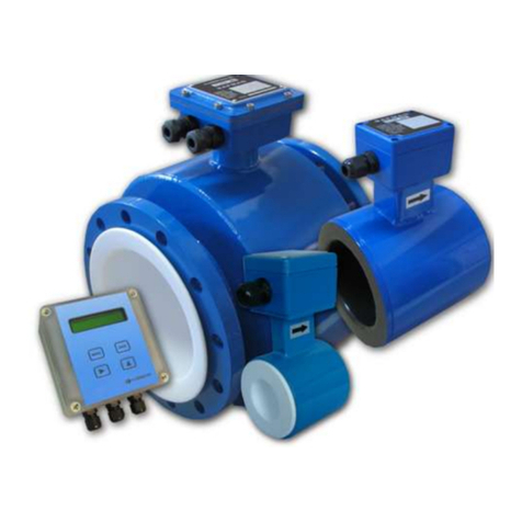
The SAFMAG ACP electromagnetic flowmeter is composed of two principle assemblies:
The meter flow sensor, which is mounted in the pipeline
The flowmeter signal converter, which is remotely mounted.
Flowtube (Sensor)
The pipeline section, or flowtube, is lined with an insulating material compatible with the
process liquid to be monitored. Two field coils are mounted on the flowtube, and these field
coils generate the electromagnetic field inside the pipe section. As conductive liquid flows
through this pipe section, a voltage is generated. In order to sense the voltage induced in the
process fluid, electrodes are inserted through the lining and flowtube. These electrodes are
chosen to be compatible with the process fluid.
Remote Electronics
The SAFMAG ACP signal converter provides pulsed AC coil excitation for the flowtube.
The ACP Hi-Puls is neither an AC Magmeter nor a pulsed DC Magmeter. The ACP Hi-Puls
combines the best from the AC and the DC pulsed systems. The Flowtube coils are powered
directly from the main supply but the power is controlled by switching 1 pulse every 1,5 cycles
for flowtubes >150mm and 1 pulse every 3,5 cycles for flowtubes <150mm. This switching
cycle creates a magnetic field nearly 2 times greater than a convential AC magmeter.
Flowtubes with pulsed AC excited fields are suitable for measuring the flow of slurries and
pulp mixtures.
In certain slurry applications, noise is generated as a result of particles impinging upon the
electrodes, and the higher frequency and voltage of the pulsed AC excited magmeter offers a
solution to these more difficult applications.
Paper stocks are more complicated, but the chemical additives found in various paper stocks
make it difficult to predict accurately whether or not noise will be a problem.
The ACP utilises a multi-tasking microprocessor to handle all functions simultaneously. The
Flowmetrix philosophy of producing easy-to-use instrumentation means that the unit can be
programmed in a matter of minutes, even without the instruction manual. The flow rate and
total are displayed continuously on a backlit LCD display, clearly visible through the viewing
window in the cast aluminium housing.

5 User’s Guide 2018
Application Guidelines
The minimum flow velocity through the SAFMAG ACP magmeter at full scale (i.e. 20mA),
should not be less than 1 metre/second. The meter diameter should therefore be selected
accordingly.
The SAFMAG ACP electromagnetic flowmeter has a minimum full-scale velocity of 1
metre/second and a maximum full-scale velocity of 10 metres/second. Velocity is calculated
from volumetric flowrate by using the following equation:
V = 1273.24 Q/D2
Where: Q is the flowrate in litres/sec
D is the nominal meter size in mm
The table below gives meter capacities for minimum and maximum full scale velocities, for all
meter sizes
Flow Rate Guide
PIPE
SIZE
PIPE
SIZE
FLOWRATE @ 1m/s (3ft/s )
FLOWRATE @ 10m/s (30ft/s)
(mm)
(INCH)
(l/s)
m3/hr
ft3/s
gal(US)/s
(l/s)
m3/hr
ft3/s
gal(US)/s
40
1.6
1.25
4.5
0.04
0.33
12.5
45
0.44
3.30
50
2
2
7.2
0.07
0.53
20
72
0.71
5.28
65
2.6
3.3
11.9
0.12
0.87
33
118.8
1.17
8.72
80
3.2
5
18.0
0.18
1.32
50
180
1.77
13.2
100
4
8
28.8
0.28
2.11
80
288
2.83
21.1
125
5
12
43.2
0.42
3.17
120
432
4.24
31.7
150
6
18
64.8
0.64
4.75
180
648
6.36
47.5
200
8
31
111.6
1.09
8.19
310
1116
10.95
81.9
250
10
49
176.4
1.73
12.9
490
1764
17.30
129.4
300
12
70
252.0
2.47
18.5
700
2520
24.72
184.9
350
14
96
345.6
3.39
25.4
960
3456
33.90
253.5
400
16
125
450.0
4.41
33.0
1250
4500
44.14
330.1
450
18
159
572.4
5.62
42.0
1590
5724
56.15
419.9
500
20
196
705.6
6.92
51.8
1960
7056
69.22
517.6
600
24
283
1018.8
9.99
74.7
2830
10188
99.94
747.4
700
28
385
1386.0
13.60
101.7
3850
13860
135.96
1016.8
750
30
442
1591.2
15.61
116.7
4420
15912
156.09
1167.3
800
32
500
1800.0
17.66
132.1
5000
18000
176.57
1320.5

6 User’s Guide 2018
Conductivity
The first parameter to consider in deciding whether or not to use a magnetic flowmeter in a
given application is conductivity. The conductivity unit of measure is microsiemens/cm or
(µS/cm). The minimum conductivity level for the SAFMAG ACP is 20 µS/cm.
Installation
Piping and Other Considerations
The SAFMAG ACP electromagnetic flowmeter should be installed in the pipeline with the
arrow in the direction of forward flow.
The meter may be installed in horizontal or vertical pipelines. If a vertical pipeline installation
is envisaged the meter should be installed with the direction of flow being upwards, to ensure
a full pipe under low flow conditions. If a horizontal installation is envisaged the meter
electrodes should be installed in the horizontal plane in order to prevent entrained air or
gasses creating a problem with the measurement.
It is essential that the meter be full of liquid at all times.
If this is not the case then the meter will produce an artificially high flowrate. If obtaining a
full meter is a problem, in some cases this may be solved by repositioning the meter at the
lowest point in a “U” shaped pipe section.
Stray electromagnetic or electrostatic fields of high intensity may have an effect on the meter
reading. For this reason the meter should not be installed close to large electric motors,
transformers, communications equipment etc.
✓
3 x D min
2 x D min
✓
✓
✓
✓
✓

7 User’s Guide 2018
NB: To ensure accurate flow measurement, the magmeter should be installed with at
least 5 pipe diameters of straight pipe upstream, and 2 pipe diameters downstream of
the magmeter.
Meter Body
The flowmeter should be lifted by a rope sling being passed around the outside of the meter
or, in the case of the large meters the lifting lugs should be used. Never pass a cable or
beam through the flowtube for lifting purposes, as this will damage the flowtube liner and
render the meter unusable. Do not support the meter by its case.
Check for alignment and spacing of pipework, as the meter should not be used to pull
pipework into alignment.
Place flange gaskets on the flange faces of the meter and position the meter between the
flange faces of the piping. Gaskets should be cut 3 mm larger than the inside diameter of
the pipe.
Insert bolts through the flanges and run washers and nuts onto the bolts. Check the piping
for alignment and the gaskets for concentricity. Tighten the nuts evenly –do not over tighten
as this may damage the liner. Bolt torque should be limited to that which will produce a
positive seal.
ACP Signal Converter Installation
The signal converter unit may be mounted up to 100 metres from the meter body. It should
be mounted on the wall or a pipe stand using normal engineering procedures and safety
procedures. Exposure of the LCD to direct sunlight should be avoided.
✓

8 User’s Guide 2018
Electrical Connections
The first rule to be observed is that the flowmeter body and the fluid should be at the same
potential to ensure accurate measurement. Normally the grounding electrode in the flowtube
or the metal pipeline ensures that the potentials are equalised.
Certain installations however, require special consideration:
Unlined metal pipelines (fig a)
In most installations where the flowtube is installed between the flanges of an unlined metal
pipeline, the grounding electrode will be sufficient for accurate measurement.
Where the process fluid has low conductivity, or if there is a possibility of induced currents in
the pipeline, grounding rings and ground connections should be installed.
Plastic or lined pipelines (fig b)
The grounding electrode will ensure accurate measurement on flowmeters up to 150 mm in
size. Above 150 mm, additional precautions may be necessary, such as grounding rings.
NB: Ensure the grounding rings are corrosion-resistant!
Pipelines with cathodic protection (fig c)
Pipelines with electric corrosion protection are generally insulated inside and outside so that
the fluid has no conductive connection to ground. The flowtube must be insulated from the
pipeline.
NB: When installing the flowmeter, ensure that the grounding rings are insulated from
the pipe flanges on both sides of the flowtube. Grounding rings, flowtube and
measuring ground must be interconnected.
Bypass the flowtube and the grounding rings with a conductor of sufficient current carrying
capacity to pass the cathodic protection current with negligible voltage drop.
Customer supplied grounding and connecting cables must have a cross section of 6mm2and
be terminated with cable lugs.
SAFMAG Flowmeters require the use of a special cable supplied by FLOWMETRIX SA for
the connections between the meter body and the remote electronics display. Refer to the
connection diagram for details.
Normal electrical and safety practices should be followed when making the electrical
connections.
NB: AC supplies should not be run in the same cable as output signal. Screened
cables should be used for all measurement signals.

9 User’s Guide 2018
Measuring ground
fig a
fig c
Measuring ground
fig b
Measuring ground

10 User’s Guide 2018
Wiring Diagram
REMOTE DISPLAY
E2 (Y)
23
SCREEN
22
GND
21
SCREEN
20
E1 (W)
19
4-20mA< /-
18
4-20mA> /+
17
0 VOLTS
16
OCT/PULSE
15
24 VOLTS
14
RELAY C
13
RELAY NC
12
RELAY NO
11
N/C
10
GND
9
N/C
8
CAL LINK
7
CAL LINK
6
COIL (B)
5
COIL (W)
4
EARTH
3
NEUTRAL
2
LIVE
1
Black
White
FLOWTUBE
16
E2
15
SCRN
14
EARTH
13
SCRN
12
E1
5
COIL
4
COIL
Yellow
White
Orange
Yellow
White
Orange
Black
White

11 User’s Guide 2018
Output Functions
•The 4 –20mA output signal is proportional to the flow rate. 4mA = 0 flow rate. The full-
scale value (i.e. 20mA) is the flow rate figure programmed into menu item M1_2 & M1_3.
OUTPUT
ACP TERMINALS
EXT. CIRCUIT
SIGNAL
Flow rate
Current Loop
(Active)
•The forward and reverse totaliser pulse output signal is either a 24V pulse available
between the 24V terminal and the PULSE terminal, or an open collector output between
PULSE terminals and the 0V terminal. The width of the pulse is selectable in menu item
M2_7, however if the pulse rate exceeds 1,33 pps, the pulse output will change to an
output with equal mark-space ratio. M2_6 is used to reduce the pulse output frequency.
PULSE
OUTPUT
ACP TERMINALS
EXT. CIRCUIT
SIGNAL
Totaliser pulse
Binary Output (Open-
Collector) External
supply and pull up
resistor
Totaliser pulse
Binary Output (Open-
Collector) External
supply and
relay/counter
Totaliser pulse
Binary Output (Open-
Collector) Internal
supply and
relay/counter
Totaliser pulse
Binary Output (Open-
Collector) Internal
supply and external
pull up resistor
Relay/
Mechanical
Totaliser
Etc.
PLC GND
PLC IN
47Ω MIN
0.5A MAX
24V MAX
0V
PULSE
0V
PULSE
24V
PULSE –ISO GND
0.8V
24V
PULSE –ISO GND
0.8V
24V
PULSE –ISO GND
0.8V
24V
PULSE –ISO GND
0.8V
24V
0V
PULSE
GND
0.5A MAX
24V MAX
0.05A MAX
PLC GND
PLC IN
470Ω MIN
0.05A MAX
24V MAX
0V
PULSE
24V
+
-
4/20-
4/20+
+
mA
-
RLOAD < 700Ω
mA
%
0
20
100
4
Relay

12 User’s Guide 2018
Relay
OUTPUT
TERMINALS
EXT. CIRCUIT
SIGNAL
Relay Output
Relay NC/NO
contacts
Relay (220VAC –
0.27A, 24VDC –2A)
NC
NO
COMMON
Relay
Mechanical
Totaliser
Etc.

13 User’s Guide 2018
Start-up and Operation
Before powering up the meter, consider the following:
•Is the meter installed according to the direction of flow as marked on the meter
•Has the wiring been carried out correctly and have all safety procedures been adhered
to
•Is the supply voltage correct
•Has the flowmeter been properly earthed
•Lethal power supply voltages may be present, do not apply power with the electronics
module cover or terminal box cover removed
•The SAFMAG is not suitable for installation in areas where explosive or flammable
gas, vapour or dust is present.
To put the SAFMAG ACP into operation, allow the pipe work to fill with liquid. Purge all
air from the pipe work and turn on the power. Allow time for the system to stabilise. With
no flow, check that the flowmeter is reading zero, that the analog output is reading 4 mA,
and that there is no pulse output.
Empty pipe detection is standard. When the converter detects high impedance in the
electrode circuit, typically caused by an empty or partially filled pipe, a signal is sent to the
microprocessor, which returns the flow reading to zero.
Although the empty pipe detection is standard, in some applications the conditions can
create a situation where the flowmeter will still read intermittently, and it is essential that
for a trouble free installation the meter be full of liquid at all times.
CALIBRATION
Factory Calibration and programming
Before despatch the signal converter has been programmed, either to the factory
standard or to those specifications advised by the customer. The SAFMAG ACP
electromagnetic flowmeter has been calibrated at FLOWMETRIX flow laboratory with
direct traceability to the National Standards. The flow sensor will hold its stated accuracy
indefinitely provided that it is correctly installed and undamaged. The signal converter can
be verified using the SAFMAG calibrator.
Calibration Coefficient
Due to the design characteristics of the various SAFMAG flowmeters, each has its own
calibration coefficient (k-factor). This coefficient is determined during the factory
calibration, and will not change unless the flowtube is damaged.
Re-Calibration
The SAFMAG ACP microprocessor signal converter has been designed for programming
simplicity. The signal converters are interchangeable, and to re-calibrate a flowmeter the
new parameters must be entered via the four push buttons.
All set-up requirements are contained in the menus, and each item is stepped to by
pressing the MENU button.
NB: The new data is only accepted if the ‘save & exit’ instruction is executed.

14 User’s Guide 2018
Menu Organisation
With the SAFMAG ACP signal converter powered up flow total and flow rate are displayed
00000000 l
5.986 l/s
Forward Total
Forward Flow
Flow Menu
Password?
* * * *
Enter the required password. The flowmeter is shipped with the password 1000. (Default
password = 1942). The signal converter set-up can be viewed without the password, however,
no changes can be saved at the Save & exit menu and the error message “wrong password”
is displayed.
Press ►repeatedly until cursor is under digit to be edited
Press ▲ repeatedly until desired value is displayed and MENU to continue
Change?
1000
Providing the correct password was entered, a new password can now be entered. Enter the
required password.
Press ►repeatedly until cursor is under digit to be edited
Press ▲ repeatedly until desired value is displayed
Press MENU to continue

15 User’s Guide 2018
MENU-1 Flow Data
Menu-1
M-cont S-enter
Press SAVE to enter or MENU to continue
M1_1 rate units
l/s
Press ▲ repeatedly until desired units are displayed and MENU to continue
M1_2 max flow
100 l/s
Enter the maximum forward flow rate at which to output 20mA Fwd current
Press ►repeatedly until cursor is under digit to be edited
Press ▲ repeatedly until desired value is displayed and MENU to continue
M1_3 flow alarm
20 l/s
Enter the flow rate at which the flow alarm must operate
Press ►repeatedly until cursor is under digit to be edited
Press ▲ repeatedly until desired value is displayed and MENU to continue
M1 -4 tot units
m3
Select the unit in which you wish to totalise
Press ▲ to select option required and MENU to continue
M1_5 clr total?
Yes/No
Select to clear or save the existing flow total
Press ▲ to select option required and MENU to continue
M1_6 damping
Level 2
level 0, level 1, level 2, level 3, level 4, level 5 damping settings are available
Press ▲ to select the required value and Mto continue

16 User’s Guide 2018
M1_7 cutoff
2 %
1%, 2%, 3%, 5% & 10% cutoff settings available
Select the level below which the signal converter will output no flow
Press ▲ to select option required and MENU to return to Main Menu
M1_8 empty pipe
activated/ deactivated
Select to activate or deactivate empty pipe if required
Press ▲ to select option required and MENU to continue

17 User’s Guide 2018
MENU- 2 Setup Data
Menu-2
M-cont S-enter
Press SAVE to enter or MENU to continue.
Enter the nominal diameter of the flowmeter stamped on the flowtube.
Press ►repeatedly until cursor is under digit to be edited
Press ▲ repeatedly until desired value is displayed and MENU to continue
M2_2 K-value
1.023
Enter the calibration coefficient stamped on the flowtube
Press ►repeatedly until cursor is under digit to be edited
Press ▲ repeatedly until desired value is displayed and MENU to continue
M2_3 Z-factor
0
Enter the Z-factor stamped on the flowtube
Press ►repeatedly until cursor is under digit to be edited
Press ▲ repeatedly until desired value is displayed and MENU to continue
M2_4 sim% fwd mA
100
The output current can be driven to any percentage of full scale by entering the desired value.
This facility can be used for testing the mA loop
Press ►repeatedly until cursor is under digit to be edited
Press ▲ repeatedly until desired value is displayed and MENU to continue
M2_5 volume/pls
1.0 l
An open collector pulse output is provided.
The output has options for 4 modes of operation, and in addition a relay output. With “pulse
o/p” option selected in M2_7 relay-opts, the output pulse occurs each time the total
increments.
Scaling of the pulse output is provided. (1.00, 0.10 & 0.01 pulse/unit options are available).
The unit of flow is that selected in M1_4.
M2_1 dia mm
100

18 User’s Guide 2018
Press ▲ to select and MENU to continue
M2_6 puls-width
10ms
Provided the output pulse rate is less than 3.125 pps, the width can be varied.
Press ▲ repeatedly until the desired value is displayed and MENU to continue
NB: the pulse output will change to a frequency with equal on-off period for a pulse rate
>3.125Hz.
M2_7 relay-opts
empty pipe
There are 4 Pulse1 options available, which also operate the relay provided the relay link is
inserted.
1) Pulse output –totalizer output
2) Reverse flow –detects change in flow direction
3) Flow alarm –detects high flowrate
4) Empty pipe –detects empty pipe condition
An isolated 24V supply is available at the output terminals limited to 30mA.
Press ▲ repeatedly until the desired option is displayed and MENU to return to Main Menu
M2_8 Slave add
1
This menu is only available in the units that are Profibus and Modbus capable.
Press ►repeatedly until cursor is under digit to be edited.
Press ▲ repeatedly until the desired slave address is entered and MENU to continue.

19 User’s Guide 2018
Cal Mode
To access the calibration menu enter the correct password and the press menu continuously
until ‘Menu-2’ is displayed. Hold MENU key depressed for 5 seconds and the Cal mode
menu will appear.
Entry to Cal mode is only possible if the correct password has been entered, and if the MENU
key is held depressed at the correct time.
Cal mode?
S-enter
This menu option is used to calibrate the 4-20mA outputs,
It can also be used in conjunction with the SAFMAG CALIBRATOR to calibrate the signal
converter. The calibration procedure is supplied with the calibrator.
CAL MENU (hidden menu)
M3_1 set 4mA
720
Connect an accurate milliamp meter to the current output terminals
Select a value that drives the output to 4.00mA (approx. 720)
Press ►repeatedly until cursor is under digit to be edited
Press ▲ to select the output required and MENU to continue
M3_2 set 20mA
3800
Connect an accurate milliamp meter to the current output terminals
Select a value that drives the output to 20mA (approx. 3800)
Press ►repeatedly until cursor is under digit to be edited
Press ▲ repeatedly until desired value is displayed
Press MENU to continue
M3_3 set I_comp
+33
Factory setting –do not change
Press MENU to continue
Table of contents
Other FLOW metrix Measuring Instrument manuals
Popular Measuring Instrument manuals by other brands
SICK
SICK WSE16 Series operating instructions

Tektronix
Tektronix P6417 instructions
Seametrics
Seametrics AG3000p quick start guide
Electro Industries/GaugeTech
Electro Industries/GaugeTech Nexus 1250 Installation & operation manual
Kramp
Kramp MT-Pro+ Operator's manual
Trail Tech
Trail Tech Vapor user manual

