ShowLed Animation Controller User manual

1
ShowLEDAnimationusermanual

2
TableofContent
Chapter1:Systemoverviewanddescription............................................................3
Systemoverview–typicalsetup...............................................................................................................3
Descriptionofthecomponents.................................................................................................................4
Chapter2:Thecontroller..........................................................................................5
Safetyinstructions.....................................................................................................................................5
Howtoreplacethefuses...........................................................................................................................5
ConnectcurtaintocontrollerandPC........................................................................................................6
OperatorConsole......................................................................................................................................7
TheStatusdisplay......................................................................................................................................8
Messagelist...............................................................................................................................................9
Bitfielddecoding.......................................................................................................................................9
TechnicalSpecifications...........................................................................................................................10
Declarationofconformity.......................................................................................................................12
Chapter3:TheShowLEDitor...................................................................................13
Softwaredownload.................................................................................................................................13
ConfiguringthePC’sIPaddress(WindowsXP).......................................................................................14
ConfiguringthePC’sIPaddress(WindowsVista)...................................................................................17
ShowLEDitorsoftware.............................................................................................................................21
Emptyspaces...........................................................................................................................................23
Errornotices............................................................................................................................................25
Chapter4:TheV‐Box..............................................................................................26
TheV‐boxthreestepset‐up:1Connect‐2Upload‐3Play.................................................................26
HowtouploadtheconfigurationfiletotheV‐box?...............................................................................27
TroubleshootingV‐boxuploadproblem.................................................................................................28

3
Chapter 1: System overview and description
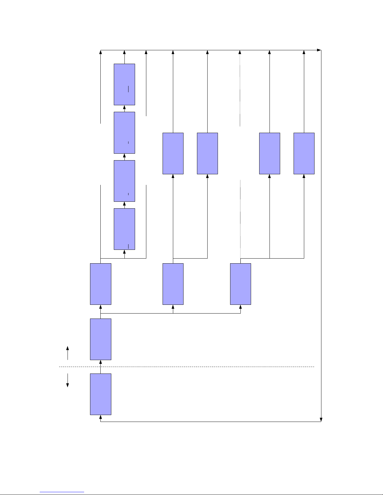
Systemoverview–typicalsetup

4
Descriptionofthecomponents
(1)PortablecomputerwithShowLEDAnimationdesignersoftwareinstalled.
AllsoftwareneededtocontroltheShowLEDAnimationcurtainisincludedinthepurchaseprice.
(2)Luminexgigabitswitch.
ThelaptoporMediaserverneedstobeconnectedwithanEthernetcabletotheShowLEDcontroller.If
morecontrollersareinprocesstheyneedtobelinkedtoeachotherviaanEthernethub.ThisEthernet
hubistheLuminexGigabitSwitchandismountedinthestandard19”touringrack.
MoreinfoontheLuminexGigabitSwitchcanbefoundonwww.luminex.be.
(3)ShowLEDAnimationcontroller.
Custombuildcontroller.
Asinglecontrollerisstoredinacustommade,trussmountableflightcase.
Ifthereismorethan1controllersuppliedthecontrollersaremountedinacustom
madetouringrack.
Moreinformationisavailableinthesection‘technicalspecifications’.
(4)Powerdistributionandswitch.
Whenthecontrollersaremountedinatouringrack,mainpowercanbeturnedon/off
byusingthepowerswitch.
(5)Extensioncables
Thecontrollerscanbeconnectedtothecurtainsbyoptionalcustommadeextensioncables.
(6)ShowLEDAnimationstarcloths
The“standard”ShowLEDAnimationstarclothshaveadimensionof4mx9m,12mx3mand5mx
7m.Thesecurtainshave1024LED’sintotalsoeachcurtainneedstobeconnectedtoasinglecontroller.
AnimationcurtainsareshippedinacustommadeShowLEDflightcase
5
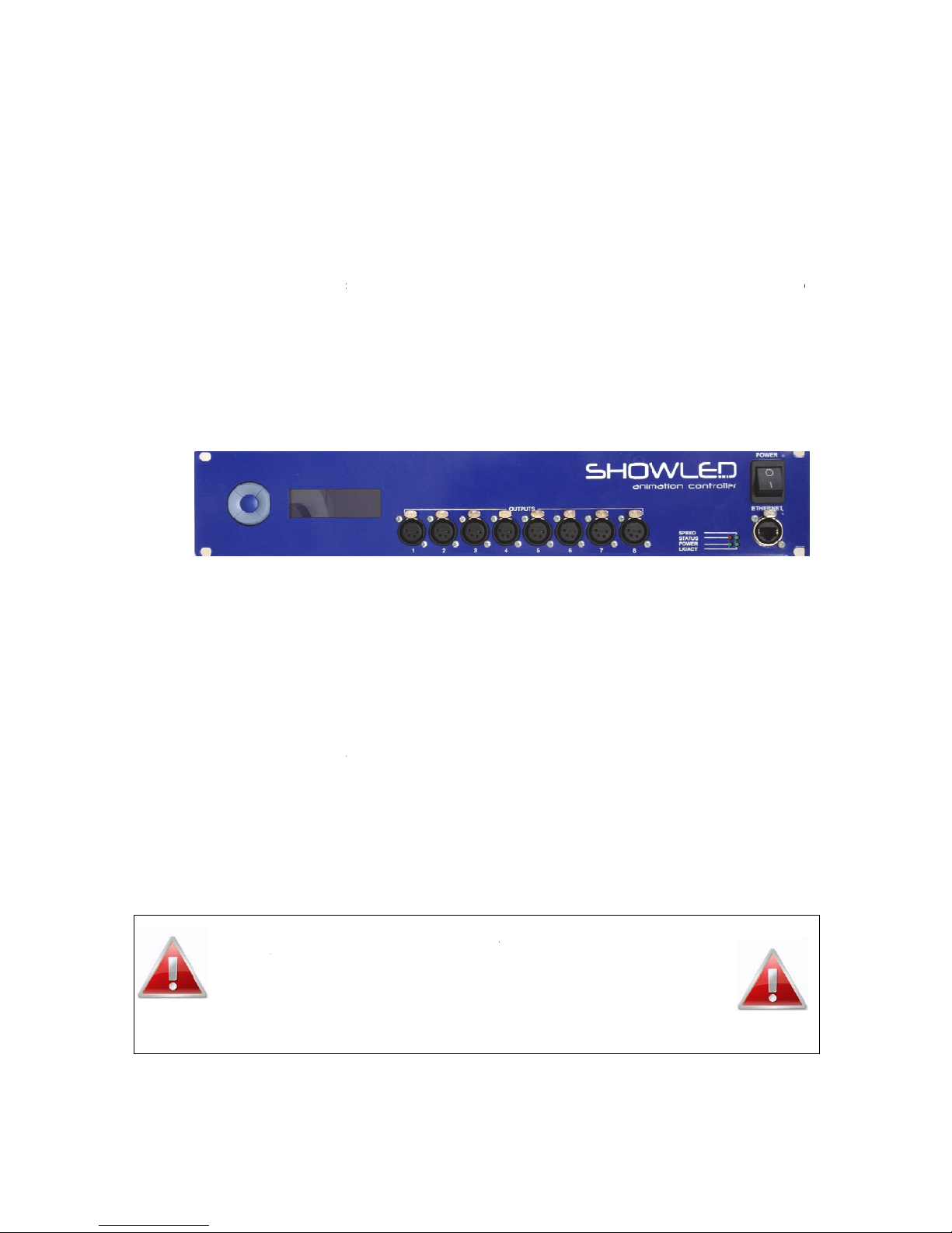
Chapter 2: The controller
Safetyinstructions
WARNING
Toavoidelectricshockthepowercordprotectivegroundingmustbeconnectedtoground.
Makesureyouunderstandthefunctionofeachconnectionbeforeyouconnectit.Seethatallconnectionsare
madecorrectlybeforeturningonthecontroller.
Alwaysdisconnectthecontrollerfromthemainssupplywhenconnectingthesignalleads,thepowercordshould
beconnectedlast.
Donotapplyvoltagehigherthan250Vactothecontroller.(Seealsotechnicaldata)
ThecontrollerhasafuseaccessibleontheIECpowerinlet;replacethemonlywiththecorrecttype.Seebelowhow
toreplacethem.
Toinsuregoodventilationinordertopreventfirecausedbyoverheating,donotinstallorusethecontrollerina
closedspace.Makesurethattheventilationexitsatthesideandthebackofthecontrollerarenotblocked.
Takecarewiththeenvironmentallimits.Donotexceedthem.(Seetechnicaldata)
Keepaminimumdistanceof1meterbetweenyou(ortheaudience)andtheLEDs.
DonotstareintotheLEDs,especiallywhennarrowangleLEDsareused.
ThiscontrollerisdesignedandtestedfordrivingLEDs;donotuseitforotherpurposes.
Donotexposethecontrollertowater(rain)ordirectsunlight.
Donotsubjecttoexcessiveshockbydroppingtheunit.
Howtoreplacethefuses
Disconnectthepowercord!Pulloutthefusedrawerbelowthemainsinputandreplacethefuseatthebackofthe
fusedrawerwiththesparefuseatthefrontofthefusedrawer.Ifthereisnosparefuseusetherightkindoffuses.
(Fuse,slowblow6.3A,20x5*mm).Connectthepowercordandcheckifthecontrollerisworkingproperly.
ShouldyouencounteranyproblemsoperatingtheShowLEDAnimationcurtain
pleasecontactShowLEDFZC.at+971(0)655.783.07or[email protected]
Nevertrytoopenup/repairtheAnimationcurtainwithoutconsultingour
technicians.
Conne
c
-
C
-
T
c
o
-
t
-
c
a
-
C
T
-
P
i
-
C
-
-
S
s
-
C
c
tcurtain
t
C
urtainandc
o
T
hecontrolle
c
ontrollerfli
g
o
rtube.Alter
It’salsopossi
t
hetouringr
a
Includedint
h
c
urtain.Thes
e
a
ndthecont
r
C
onnectplug
s
T
heplugsar
e
P
leasenotet
h
i
n/outputdo
e
C
onnectpow
e
Linkcontrolle
S
witchcontr
o
s
houldrea
d
C
ontinuewit
h
Should
y
please
Neve
r
t
ocontrol
o
ntrollerare
t
rislikewise
b
g
htcase,you
w
natively,the
c
blethatthe
c
a
ck.
h
eflightcase
e
cablescan
b
r
oller.Simply
c
s
tocontrolle
r
e
nothotswa
p
h
atfornowo
n
e
sn’toperate
y
e
rcordofco
n
e
rviaEtherne
t
o
llerON.The
d
“READS
h
ManualSho
w
youencoun
t
contactSho
w
r
trytoopen
lerandP
C
t
ransportedi
n
b
uiltinaspec
i
w
illnoticeth
a
c
ontrollerca
n
c
ontrollersar
e
areextensio
n
b
eusedifth
e
c
onnectexte
n
r
.
p
pable,alwa
y
n
lytheeight
p
y
et.
n
trollertopo
w
t
cabletoPC.
controllerwi
UCCES”8
w
LEDitor
t
eranyprob
l
w
LEDFZC.a
t
up/repairt
h
6
C
n
blueShowL
E
i
aldesigneds
t
a
tthereisa
t
n
beplacedo
n
e
installedin
a
n
cables,the
e
re’sabigdi
s
n
sioncablest
o
y
smakesure
t
p
luginputsa
n
w
ersupply.
lldetectthe
times.The
l
emsoperati
t
+971(0)65
5
h
eAnimati
o
technicia
n
E
Dflightcase
s
t
oragecase.
W
t
russclampf
o
n
theground.
a
19’touring
r
lengthofthe
s
s
tancebetwe
o
cablescomi
t
hecontrolle
r
n
dtheEthern
e
insertedplug
ndisplay
i
ngtheSho
w
5
.783.07or
s
o
ncurtainw
i
n
s.
s
.
W
henremovi
o
reasyattac
h
r
ack.Pleaser
e
s
ecablesde
p
enthecable
s
ngoutofthe
r
isturnedoff
e
tinputaref
u
s.Ifyou’vea
t
shouldrea
d
w
LEDAnimat
i
s
upport@sh
o
i
thoutcons
u
ngfrontand
h
mentofcon
t
e
movefront
a
p
endsonthe
s
comingout
curtain.
whenyouin
s
u
nctional.The
t
tached8pl
u
d
8PLUG
S
i
oncurtain
o
wled.com
u
ltingour
b
acklidofth
e
t
rollertotrus
s
a
ndbacklid
o
surfaceofth
e
ofthecurtai
n
s
erttheplugs
.
DMX
u
gsthedispla
y
S
DETECTE
D
e
s
o
f
e
n
.
y
D
.
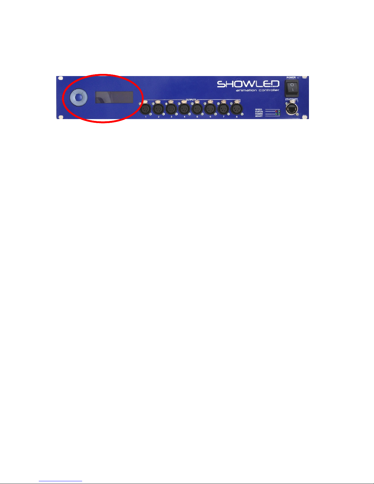
Opera
t
Theoper
Thiscon
s
thepara
m
Usethe
b
TheUPb
TheDO
W
TheLEFT
TheRIG
H
Pressth
e
t
orConsol
atorconsole
c
s
oleistheph
y
m
etersofthe
b
uttons(Up,
D
uttonletsyo
u
W
Nbuttonlet
s
buttonletsy
o
H
Tbuttonlets
e
UPbuttona
e
c
onsistsofa
L
y
sicalinterfac
e
controller.
D
own,Leftan
d
u
scrollupin
t
s
youscrolld
o
o
ugobackin
youtoselect
ndthenthe
D
L
CDdisplaya
n
e
thatletsyo
u
d
Right)tosc
r
t
hemenustr
u
o
wnordecre
a
themenustr
ortoconfir
m
D
OWNbutto
n
7
n
dakeypad
w
u
accessthe
m
r
ollthrought
h
u
ctureorincr
e
a
seaparame
t
ucture.
m
amenuite
m
n
tounlockth
w
ithfivepush
m
enustructur
h
emenustru
c
e
aseaparam
e
t
er.
m
.
ekeypad.
buttons.
e.Themenu
s
c
ture.
e
ter.
s
tructurelets
youmodify

8
TheStatusdisplay
AfterpoweringonthedevicetheLCDdisplaysthecontrollerstatus.
Statusdisplay,line1
Displaysthenumberofvalidplugsdetected.
Thisshouldbethesameamountofplugsconnectedtothecontroller.
e.g. 8validplugs
Statusdisplay,line2
ThislinedisplaystheIP‐addressthatthecontrollerhasontheEthernetnetwork.
Theletterdirectlyaftertheaddressrevealsthetypeofaddressing.
AstandsforautomaticIPaddressing
SstandsforstaticIPaddressing
DstandsfordynamicIPaddressing(bymeansofaDHCP)
Statusdisplay,line3
Mostofthetime,thiswillbeablankline.
Inaspecialcasethislinewilldisplaythenumberof‘blankplugsdetected’(seealsorepairprocedure)
Anotherspecialcaseisthemessage‘Makeredundantnow!’.
Whenyouseethismessageit’sadvisabletodothisbyfollowingtheMainMenu/Utilities/Createredundancy
branchofthemenustructure.
Statusdisplay,line4
Delastlineisreservedforsystemmessages.
Amessagecanbeneutralorbeanerrormessage.
Note,thislinecanalsobeblank.
e.g. ReceivingLEDData
9
Messagelist
messagemeaning
ReceivingLEDDataThecontrollerreceivesEthernetdatameantforprojectiontothe
animationclothconnectedtoit.
NoEthernetLinkThereisnoworkingEthernetlinkwiththiscontroller.
Pleasecheckcablesandnetworkgeartoresolvethisproblem.
DON'THOTSWAPPLUGSThecontrollerhasdetectedapowersurgeononeofhisoutputports.It’s
mostprobablecausedbyinsertingapluginanoutputportwhilethe
deviceispowered.It’sadvisabletoonlypluginconnectorswhenthe
deviceispoweredoff.
OConportxyzThereisanovercurrentontheports‘xyz’.
Seethetroubleshootmanualtoresolvethis.
e.g. OConport257
onesupplyfailsOneoftheinternalpowersuppliesfails.
Seethetroubleshootmanualtoresolvethis.
Fan1failsFan1isjammed,brokenorthecablehascomeloose.
Fan2failsFan2isjammed,brokenorthecablehascomeloose.
Fan1&2failsBothfansarejammed,brokenorthecableshavecomeloose.
TemptoohighThecabinettempistoohigh.Pleaseresolvethisproblem.
Makesurethattheventilationinlets(twosides)andventilationoutlets
(back)arefree.
S00000000X11111111Whenthereismorethanoneerroratsametimethisbitfieldnotationis
used.
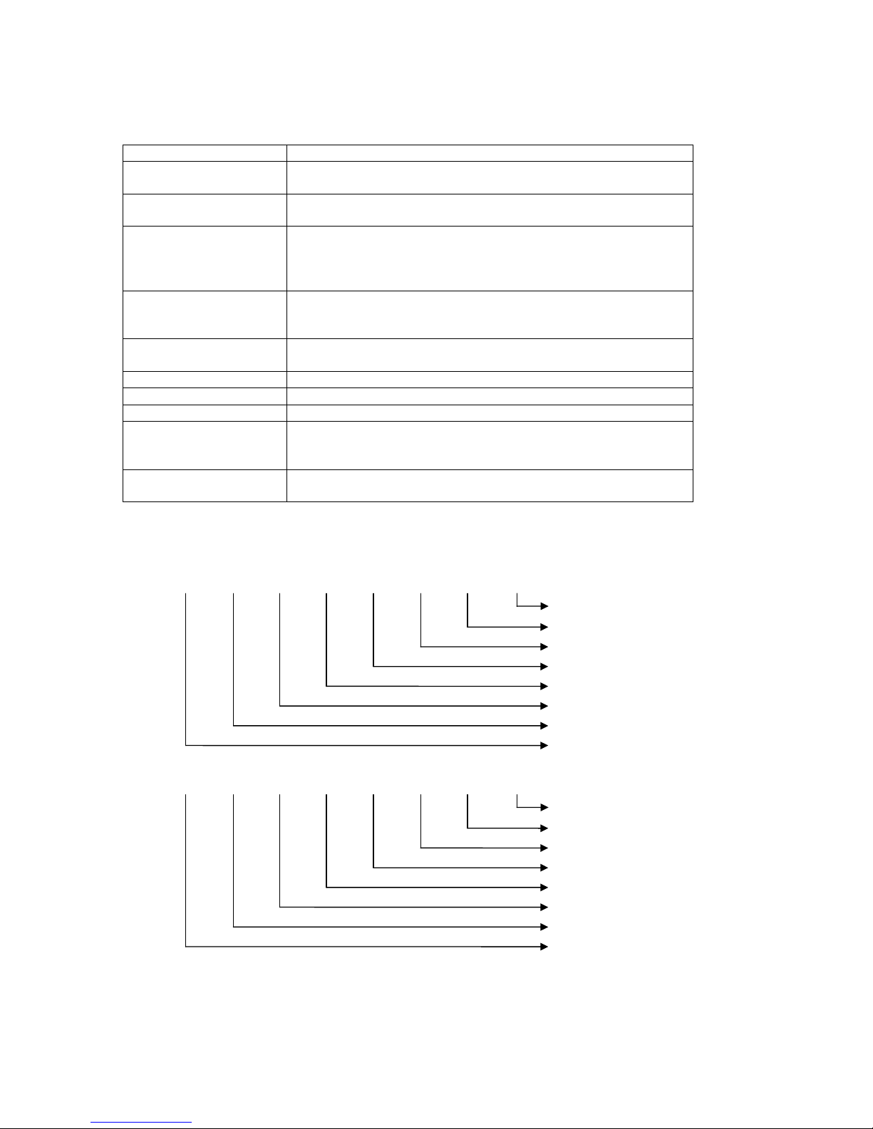
Bitfielddecoding
Sbit7bit6bit5bit4bit3bit2bit1bit0
1=Temptoohigh
1=Fan1fails
1=Fan2fails
1=onesupplyfails
1=OverCurrent
Always0
Always0
Always0
Xbit7bit6bit5bit4bit3bit2bit1bit0
1=OConport1
1=OConport2
1=OConport3
1=OConport4
1=OConport5
1=OConport6
1=OConport7
1=OConport8
10
8 valid plugs
IP:10.0.3.233 A
Receiving LEDData
[ Main Menu ]
>Network Settings
Information
U/D=scroll select>
[ Information ]
>Show MAC / IP
Show HW/FW version
U/D=scroll select>
[ Utilities ]
>Repair plug
LED test
U/D=scroll select>
[ IP addressing ]
>Auto IP (prefered)
Static IP
U/D=scroll select>
[ NETWORK INFO ]
MAC:00036402204D
IP:10.0.3.233
[ DEVICE INFO ]
Firmware 2.0
Hardware 3.0
Cabinet temp 27
[ modify address ]
IP byte 1
10.0.3.233
U/D=modify confirm>
LED test running…
Press the middle
button to stop
CREATING redundancy
DO NOT POWER OFF
[ modify address ]
IP byte 2
10.0.3.233
U/D=modify confirm>
[ modify address ]
IP byte 3
10.0.3.233
U/D=modify confirm>
[ modify address ]
IP byte 4
10.0.3.233
U/D=modify confirm>
Menu structure
Status display Active menu
Sets the IP addressing to Auto IP
Sets the IP addressing to DHCP client
Starts the ‘repair’ procedure

11
TechnicalSpecifications
Input
‐Supplyvoltage:90..250Vac
‐Linefrequency:50..60Hz
‐Inputcurrent:4.4A(@115Vac)/2.4A(@230Vac)
‐Inputpower:450Watt
‐Fuses,slowblow,6.3A,20x5mm
‐Mainsinput:standardizedIECpowerinlet
‐PFC(PowerFactorCorrection)circuitpresent
LEDOutputs(8XLRsintotal,eachoutputcandrive128LEDs)
‐OutputVoltage:24V
‐TotalOutputPower:400Watt
DataPorts
‐Ethernetport10/100Mbps
Environmental
‐Operatingtemperature,humidity*:0°C..+50°C,<80%RH
‐Storagetemperature,humidity*:0°C..+50°C,<60%RH
(*non‐condensing)
Mechanical
‐Dimensions:483x88x138mm(19’rackmountable)
‐Weight:3.32kg

12
Declarationofconformity
We,ShowLEDFZC
SharjahInternationalAirportFreeZone,Sharjah,UAE
Declarethattheproduct
ShowLEDAnimationSystem
isinconformitywiththeessentialrequirementsofthefollowingdirectivesandstandards:
LowVoltageDirective(73/23/EEC)
IEC60065,12‐2005(Edition7.1)
Audio,videoandsimilarelectronicapparatus–Safetyrequirements
EMCDirective(89/336/EECand92/31/EEC)
EN55103‐1,11‐1996Electromagneticcompatibilityforaudio,video,audio‐visualandentertainment
lightingcontrolapparatusforprofessionaluse.
Part1:Emission
EN55103‐2,11‐1996Electromagneticcompatibilityforaudio,video,audio‐visualandentertainment
lightingcontrolapparatusforprofessionaluse.
Part2:Immunity
EN55022Standardsofradiodisturbanceofinformationtechnologyequipment
Sharjah,UAE JimmyPieters,R&DManager
01/09/2011
______________________________________
(Dateofissue)(Signatureofauthorisedperson)

13
Chapter 3: The ShowLEDitor
Softwaredownload
TheShowLEDsoftwarecanbedownloadedfromtheShowLedwebsite:
www.showled.com/downloads
Thereare2applicationsthatyouneedtoinstall:theShowLEDitorandtheLEDfilterapplication.
Whenyou’veinstalledallthenecessarysoftwareyouneedtoconfigureyourPCinthecorrectwayasdescribed
below.
14
ConfiguringthePC’sIPaddress(WindowsXP)
1. MakesureyourlaptoporPChasafixedIPaddress.Hereishowyoucandothis.
•StartControlPanel
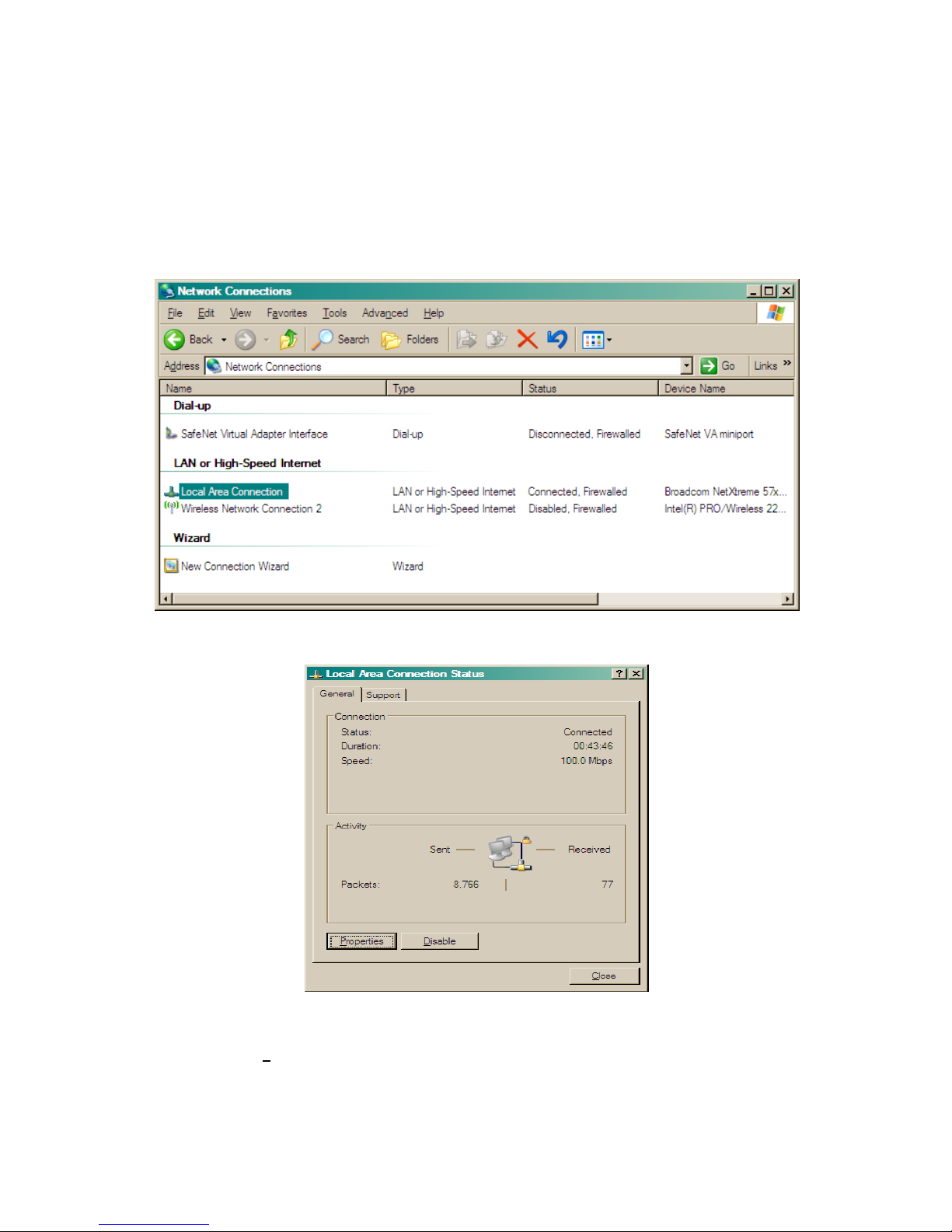
•InControlPanel,startNetworkConnections,thisiswhatyouwillsee:
•StartLocalAreaConnectionandyouget:
•ClickonthePropertiesbuttonandyouget:

15
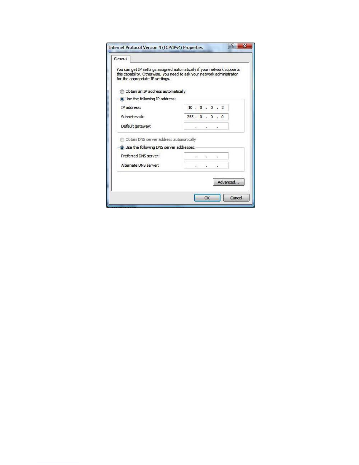
•LookforInternetProtocol(TCP/IP)inthelist,doubleclickontheitem,andyouwillget:
•Enterthefollowingdataintothescreen:

16
•TheIPaddressmustbeintherangeof10.0.0.x
•ClickOKandcloseallwindows.Thismaytakesometime.RestartyourlaptoporPC.

17
ConfiguringthePC’sIPaddress(WindowsVista)
DoubleclickontheInternetconnectioniconlocatedinthebottomrightcornerofyourdesktopandclickon
“NetworkandSharingCentre”..
Thefollowingwindowwillopen.Pleaseclickon“Managenetworkconnections”inthefarleftcorner.
Thiswillopenfollowingwindow.

18
Rightclickon“LocalAreaConnection”andselect“properties”.

19
Select“InternetProtocolVersion4”andclickon“properties”
20
Inthepropertieswindowyouneedtoticktheboxinfrontof“usefollowingIPaddress”andyouneedtofillinthe
value10.0.0.2.Thesubnetmaskvaluewillbesetautomaticallyto255.0.0.0.
ClickokandrestartyourPC.It’srecommendedtoturnoffWindowsfirewallandtorunallthesoftwareas
administrator
Table of contents
Other ShowLed Lighting Equipment manuals


