showtech DMX512 User manual

4
32CH DMX512 Constant Voltage Decoder32CH DMX512 Constant Voltage Decoder
2
1、Brief Introduction
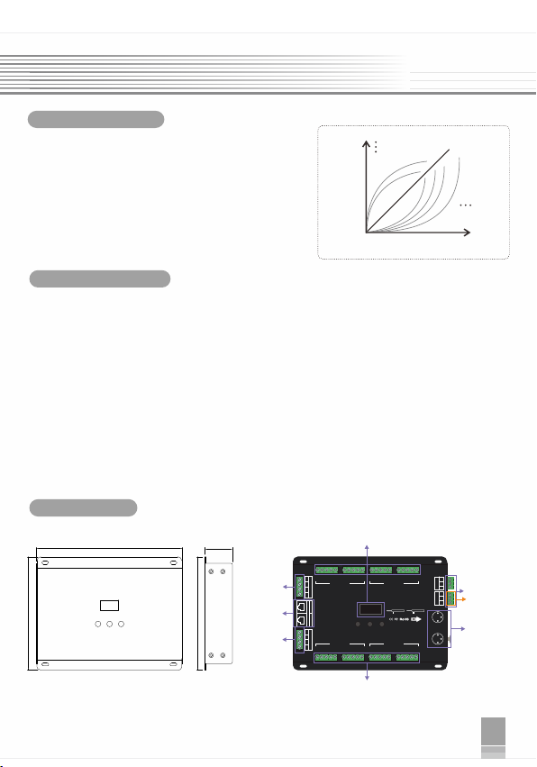
2、Specifications
32CH DMX512 Constant Voltage Decoder
UserManual
Model
Input voltage
Max load current
Max output power
Output scale level
Input signal
Output DMX channel
Output frequency
Decode channel
DMX512 socket
Control mode
Dimension
Weight (G.W)
32CH DMX512 Decoder
DC5V-24V
,Max 96A
3A×32CH
480W(5V)/1152W(12V)/2304W(24V)
256 levels(8bit)/65536 levels(16bit)
DMX512/RDM
Constant Voltage PWM×32CH
1K、2K、4K、8K selectable
32CH
XLR-3R/ RJ45/ Terminal block
DIM /CT /RGB /RGBW 4 modes switch
L195 X W145 X H38(mm)
810g
3、Basic Features
(Please read through this manual carefully before use)
1
32CH DMX512 Constant Voltage Decoder32CH DMX512 Constant Voltage Decoder
6、Conjunction Diagram
1. Connect to DMX system:
4、Safety warnings
5、Interfaces
Welcome to use the DMX512 Constant Voltage Decoder, designed for Hi-power multiple channels
application, which is developed only for constant voltage LED lamps. It adopts advanced micro-
computer control technology to transfer DMX512/1990 signal to PWM signal. 32 channels output,
Max. 3A each channel, up to 2304W output power, 65536 gray scales, workable for single color, color
temperature, RGB and RGBW led lamp.
5
32CH DMX512 Constant Voltage Decoder
3
6
32CH DMX512 Constant Voltage Decoder
8、After-Sales
From the day you purchase our products within 3 years, if being used properly in accordance
with the instruction, and quality problems occur, we provide free repair or replacement services
except the following cases:
1.Any defects caused by wrong operations.
2.Any damages caused by inappropriate power supply or abnormal voltage.
3.Any damages caused by unauthorized removal, maintenance, modifying circuit, incorrect
connections and replacing chips.
4.Any damages due to transportation, breaking, flooded water after the purchase.
5.Any damages caused by earthquake, fire, flood, lightning strike etc force majeure of natural
disasters.
6.Any damages caused by negligence, inappropriate storing at high temperature
and humidity environment or near harmful chemicals.
7.Product has been updated.
9、Kindly Reminder
Power source must be DC constant voltage type of power supply. Due to the efficient output in some
power supplies are only 80% of total, so please select at least 20% higher output power supply than
the consumption of LED lights.
Power Source Selection:
Update Time: 2019.4.10
Gamma
value
DMXValue
Output
brightness
0
100%
2.5 3.5
6.5
1.0
0.8
0.9
<1
>1
1.5
255
1. Easy operation with OLED screen and touch buttons.
2. 8bit (256 levels)/16bit (65536 levels) grey level optional.
3. Support 3 kinds of DMX ports with signal isolation function:
3-pin XLR, RJ45
and green terminal (with signal amplifier function).
4. With the operations can be
RDM master console, such as parameters
setting, equipment recognition, etc.
RDM remote management protocol,
completed via the
browsing & setting, DMX address
5. Optional for standard, linear, LOG or custom 0.1-9.9 dimming curve.
6. Power-off data saved function.
Please don’t install this controller in lightening, intense magnetic and high-voltage fields.
1.To reduce the risk of component damage and fire caused by short circuit, make sure correct
connection.
2.Always be sure to mount this unit in an area that will allow proper ventilation to ensure a fitting
temperature.
3.Check if the voltage and power adapter suit the controller
(please select DC12-24V power supply with constant voltage)
4.Don’t connect cables with power on; make sure a correct connection and no short circuit checked
with instrument before power on.
5.Please don’t open controller cover and operate if problems occur.
The manual is only suitable for this model; any update is subject to change without prior notice.
use of
6.When the signal line is long or the wire quality causes the signal recoil effect to affect the
each signal line to
product, you can try to connect 0.25W 90-120Ω terminating resistor at the end of
solve.
Inp ut:5 V-24 VDCInp ut:5 V-24 VDC
I(o ut) : 3A×32C H Max 9 6AI(o ut) : 3A×32C H Max 9 6A
P(o ut) :(0~ 15. ..7 2W)×3 2CHP(o ut) :(0~ 15. ..7 2W)×3 2CH
Inp ut:5 V-24 VDC
I(o ut) : 3A×32C H Max 9 6A
P(o ut) :(0~ 15. ..7 2W)×3 2CH
32 Cha nnel 8/16Bi ts 32 Cha nnel 8/16Bi ts
Phot oelec tric Is olati onPhotoe lectr ic Isol ation
32 Cha nnel 8/16Bi ts
Phot oelec tric Is olati on
V+
V+V+
R
RR
G
GG
B
BB
W
WW
DC1 MAX 24A
DC1 MAX 24ADC1 MAX 24A
V+
V+V+
R
RR
G
GG
CH
CHCH
1
11
2
22
3
33
4
44
CH
CHCH
5
55
6
66
G
GG
B
BB
W
WW
DC4 MAX 24A
DC4 MAX 24ADC4 MAX 24A
V+
V+V+
R
RR
G
GG
B
BB
W
WW
27
2727
28
2828
CH
CHCH
29
2929
30
3030
31
3131
32
3232
DC4
DC4DC4 DC3
DC3DC3
DC3
DC3DC3
DC4
DC4DC4
+
++
-
--
+
++
-
--
POW ER INPOW ER INPOW ER IN
DC2
DC2DC2 DC1
DC1DC1
DC1
DC1DC1
DC2
DC2DC2
-
--
+
++
-
--
+
++
1: DATA+ 2:DATA- 7&8: GND1: DATA+ 2:DATA- 7&8: GND1: DATA+ 2:DATA- 7&8: GND
RDM/DMXINRDM/DMXINRDM/DMXIN RDM/DMXOUTRDM/DMXOUTRDM/DMXOUT
1......8
1......81......8
1......8
1......81......8
POW ER INPOW ER INPOW ER IN
DMX51 2 DE CODERDMX51 2 DE CODERDMX51 2 DE CODER
MMM+++---
B
BB
W
WW
7
77
8
88
V+
V+V+
R
RR
G
GG
B
BB
W
WW
DC2 MAX 24A
DC2 MAX 24ADC2 MAX 24A
V+
V+V+
R
RR
G
GG
B
BB
W
WW
CH
CHCH
9
99
10
1010
11
1111
12
1212
CH
CHCH
13
1313
14
1414
15
1515
16
1616
V+
V+V+
R
RR
G
GG
B
BB
W
WW
DC3 MAX 24A
DC3 MAX 24ADC3 MAX 24A
V+
V+V+
R
RR
G
GG
B
BB
W
WW
CH
CHCH
17
1717
18
1818
19
1919
20
2020
CH
CHCH
21
2121
22
2222
23
2323
24
2424
V+
V+V+
R
RR
CH
CHCH
25
2525
26
2626
1
11
2
22
3
33
RDM/DMX OUT
RDM/DMX OUTRDM/DMX OUT
2
22
1
11
3
33
RDM/DMX IN
RDM/DMX INRDM/DMX IN
1: GND
1: GND
2: DATA-
2: DATA-
3: DATA+
3: DATA+
1: GND
2: DATA-
3: DATA+
DMXAMP
DMXAMPDMXAMP
RDM/DMXIN
RDM/DMXINRDM/DMXIN
D
DD
+
++
-
--
GND
GNDGND
D
DD
D
DD
+
++
-
--
GND
GNDGND
D
DD
POWERDC1~DC4
POWERDC1~DC4POWERDC1~DC4
5.5-7.5mm wire prep.
5.5-7.5mm wire prep.5.5-7.5mm wire prep.
2.5-4.0/13-10AWG
2.5-4.0/13-10AWG2.5-4.0/13-10AWG
OUTPUTCH1~CH32
OUTPUTCH1~CH32OUTPUTCH1~CH32
5.5-7.5mm wire prep.
5.5-7.5mm wire prep.5.5-7.5mm wire prep.
1.5-2.5/16-12AWG
1.5-2.5/16-12AWG1.5-2.5/16-12AWG
RDM
RDMRDM
DMX
DMXDMX
195mm
145mm
145mm
38mm
RJ45
3-pinXLR
Main component description:
OLED screen
Green terminals
With signal
amplifier function
Power input
Power input
Green terminals
LED lamps connection
DMX OU T
DMX IN
DMX OU T
DC12-24V
LED
LEDLEDLEDLED
LED LED L ED
LED
LEDLEDLEDLED
LED LED L ED
DMX IN
PowerSupply
7、Operating instructions
Modes Description
Brightness adjustable
M0
NO
M1
M2
M3
M4
M5
M6
M7
M8
M9
M10
RGBW can be dimmed separately in static mode
Brightness, speed adjustable
All mode cycle
3 color skipping
7 color skipping
White color strobe
3 color smooth
Full color smooth
RG color smooth
R B color smooth
GB color smooth
White color fade & change
Great cycle
Brightness, speed adjustable
Brightness, speed adjustable
Brightness, speed adjustable
Brightness, speed adjustable
Brightness, speed adjustable
Brightness, speed adjustable
Brightness, speed adjustable
Brightness, speed adjustable
6. Instruction:
a) 8 outputs controlled synchronously when in test mode.
b) Test mode as below:
DC5-2 4V
DC5-24V
DC5-24V
DC5-2 4V
PowerSupply
PowerSupply
PowerSupply
PowerSupply
DMX Bit : 8
Output Freq : 1.0K
Output Mode : RGBW
DMX Addr : 001
DMX Bit : 8
DMX Addr : 001
DMX Bit : 8
Output Freq :1.0K
Output Mode : RGBW
DMX Addr : 001
Output Freq :1.0K
Output Mode : RGBW
DMX Addr : 001
Output Freq : 1.0K
Output Mode : RGBW
DMX Bit : 8
Output Curve: 1.0
Enter Test Mode
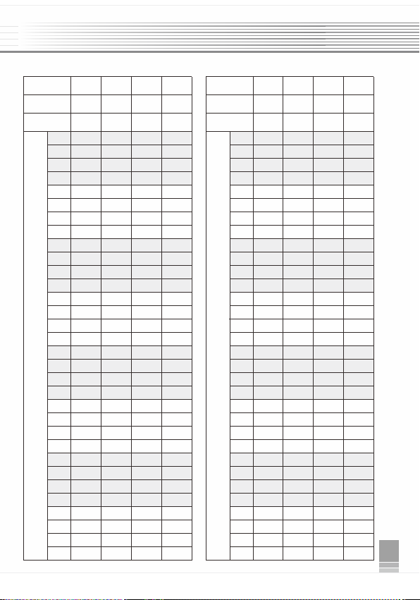
Address setting table
DIM DIM
CT CT RGB RGB RGBW RGBW
ChannelChannel
81616 32
24 48
32 64
8bit 16bit8bit 16bit8bit 16bit8bit 16bit
1
2
3
4
5
6
7
8
9
10
11
12
13
14
15
16
17
18
19
20
21
22
1
2
3
4
5
6
7
8
9
10
11
12
13
14
15
16
17
18
19
20
21
22
001 001 001 001
004 007 010 013
001 002 002 002
004 008 011 014
001 001 003 003
004
007 012 015
001 002 001 004
004
008 010 016
002 003 004 005
005 009 013 017
002 004 005 006
005 010 014 018
002 003 006 007
005 009 015 019
002 004 004 008
005 010 013 020
003 005 007 009
006 011 016 021
003 006 008 010
006 012 017 022
003 005 009 011
003 006 007 012
Address
Quantity
Address
Quantity
Resolution Resolution
Mode Mode
001
002
001
002
001
002
001
002
001
002
005
006
001
002
005
006
005
006
005
006
005
006
005
006
005
006
007
008
007
008
007
008
007
008
009
010
009
010
009
010
009
010
011
012
011
012
011
012
007
008
013
014
013
014
015
016
015
016
017
018
017
018
019
020
021
022
023
024
013
014
011
012
005
006
001
002
003
004
003
004
003
004
003
004
003
004
003
004
003
004
003
004
001
002
001
002
007
008
007
008
013
014
015
016
019
020
021
022
025
026
027
028
013
014
015
016
023
024
019
020
029
030
031
032
007
008
007
008
009
010
009
010
009
010
009
010
011
012
011
012
017
018
017
018
025
026
027
028
029
030
025
026
031
032
033
034
033
034
035
036
037
038
039
040
041
042
043
044
019
020
019
020
021
022
023
024
23
24
25
26
27
28
29
30
31
32
23
24
25
26
27
28
29
30
31
32
007 013 019 025
007 014 020 026
007 013 021 027
007 014 019 028
008 015 022 029
008 016 023 030
008 015 024 031
008 016 022 032
006 011 018 023
006 012 016 024
011
012
011
012
035
036
045
046
047
048
031
032
021
022
023
024
013
014
013
014
015
016
015
016
015
016
015
016
025
026
027
028
029
030
029
030
031
032
031
032
041
042
037
038
043
044
045
046
053
054
047
048
055
056
057
058
059
060
061
062
063
064
043
044
013
014
027
028
039
040
051
052
013
014
025
026
037
038
049
050
DMX IN
DMX OU T
DMX IN
LED
LEDLEDLEDLED
DC5-24V
DC5-24V
LED LED L ED
LED
LEDLEDLEDLED
DC5-24V
DC5-24V
LED LED L ED
DMX OUT
PowerSupply
PowerSupply
PowerSupply
PowerSupply
OLED screen interface:
2. DMX address setting
Press “+" or “-" key to set
DMX address.
Range: 001~512
Main page
3. PWM frequency
8K、4K、2K、1K
It is recommended to use 1K
Press “+" or “-" key to choose.
Optional :
Press “+" or “-" key to choose.
Optional :
DIM、CT、RGB、RGBW
4. Mode 5. Grey scale
Press “+" or “-" key to choose.
Optional : 8bit
16bit (choose it if the master
controller support this function)
6. Dimming curve
Press “+" or “-" key to choose.
Optional : 0.1~9.9 (only 8bit can
be set)
It is recommended to use 1.8
0.1-9.9 is for special requirements.
2. Work with RDM controller:
1. Lock screen interface:
No operation after 10 seconds
into the lock screen interface,
display only has set up a good
parameter, long press the M
key for 2 seconds to unlock.
The star symbol flashes when
there is DMX signal in.
7.Built-in test
R: 000 G: 000
B: 000 W: 000
Curve: 1.8 Exit
Mode: M0 bit8
Press “+" or “-" key to choose.
Optional: Mode M0-10
Digits 8bit or 16bit
Grey scale 0-255 or 0-65536
Gamma value 0.1-9.9(only 8bit
can be set)
Note: RDM controller can only be used normally with 3-pin XLR terminals.
A:001B:8F:1.0
M:RGBWC:1.8 *
DecodeMode,Long
press'M'unlock
Press "M" key, switch entries.
Press "+" or “-" key, parameter adjustment.
Exit: back to previous page.
Long press three buttons in case of
power off.
Restar to restore the factory settings.
4
32CH DMX512 Constant Voltage Decoder32CH DMX512 Constant Voltage Decoder
2
1、Brief Introduction
2、Specifications
32CH DMX512 Constant Voltage Decoder
UserManual
Model
Input voltage
Max load current
Max output power
Output scale level
Input signal
Output DMX channel
Output frequency
Decode channel
DMX512 socket
Control mode
Dimension
Weight (G.W)
32CH DMX512 Decoder
DC5V-24V
,Max 96A
3A×32CH
480W(5V)/1152W(12V)/2304W(24V)
256 levels(8bit)/65536 levels(16bit)
DMX512/RDM
Constant Voltage PWM×32CH
1K、2K、4K、8K selectable
32CH
XLR-3R/ RJ45/ Terminal block
DIM /CT /RGB /RGBW 4 modes switch
L195 X W145 X H38(mm)
810g
3、Basic Features
(Please read through this manual carefully before use)
1
32CH DMX512 Constant Voltage Decoder32CH DMX512 Constant Voltage Decoder
6、Conjunction Diagram
1. Connect to DMX system:
4、Safety warnings
5、Interfaces
Welcome to use the DMX512 Constant Voltage Decoder, designed for Hi-power multiple channels
application, which is developed only for constant voltage LED lamps. It adopts advanced micro-
computer control technology to transfer DMX512/1990 signal to PWM signal. 32 channels output,
Max. 3A each channel, up to 2304W output power, 65536 gray scales, workable for single color, color
temperature, RGB and RGBW led lamp.
5
32CH DMX512 Constant Voltage Decoder
3
6
32CH DMX512 Constant Voltage Decoder
8、After-Sales
From the day you purchase our products within 3 years, if being used properly in accordance
with the instruction, and quality problems occur, we provide free repair or replacement services
except the following cases:
1.Any defects caused by wrong operations.
2.Any damages caused by inappropriate power supply or abnormal voltage.
3.Any damages caused by unauthorized removal, maintenance, modifying circuit, incorrect
connections and replacing chips.
4.Any damages due to transportation, breaking, flooded water after the purchase.
5.Any damages caused by earthquake, fire, flood, lightning strike etc force majeure of natural
disasters.
6.Any damages caused by negligence, inappropriate storing at high temperature
and humidity environment or near harmful chemicals.
7.Product has been updated.
9、Kindly Reminder
Power source must be DC constant voltage type of power supply. Due to the efficient output in some
power supplies are only 80% of total, so please select at least 20% higher output power supply than
the consumption of LED lights.
Power Source Selection:
Update Time: 2019.4.10
Gamma
value
DMXValue
Output
brightness
0
100%
2.5 3.5
6.5
1.0
0.8
0.9
<1
>1
1.5
255
1. Easy operation with OLED screen and touch buttons.
2. 8bit (256 levels)/16bit (65536 levels) grey level optional.
3. Support 3 kinds of DMX ports with signal isolation function:
3-pin XLR, RJ45
and green terminal (with signal amplifier function).
4. With the operations can be
RDM master console, such as parameters
setting, equipment recognition, etc.
RDM remote management protocol,
completed via the
browsing & setting, DMX address
5. Optional for standard, linear, LOG or custom 0.1-9.9 dimming curve.
6. Power-off data saved function.
Please don’t install this controller in lightening, intense magnetic and high-voltage fields.
1.To reduce the risk of component damage and fire caused by short circuit, make sure correct
connection.
2.Always be sure to mount this unit in an area that will allow proper ventilation to ensure a fitting
temperature.
3.Check if the voltage and power adapter suit the controller
(please select DC12-24V power supply with constant voltage)
4.Don’t connect cables with power on; make sure a correct connection and no short circuit checked
with instrument before power on.
5.Please don’t open controller cover and operate if problems occur.
The manual is only suitable for this model; any update is subject to change without prior notice.
use of
6.When the signal line is long or the wire quality causes the signal recoil effect to affect the
each signal line to
product, you can try to connect 0.25W 90-120Ω terminating resistor at the end of
solve.
Inp ut:5 V-24 VDCInp ut:5 V-24 VDC
I(o ut) : 3A×32C H Max 9 6AI(o ut) : 3A×32C H Max 9 6A
P(o ut) :(0~ 15. ..7 2W)×3 2CHP(o ut) :(0~ 15. ..7 2W)×3 2CH
Inp ut:5 V-24 VDC
I(o ut) : 3A×32C H Max 9 6A
P(o ut) :(0~ 15. ..7 2W)×3 2CH
32 Cha nnel 8/16Bi ts 32 Cha nnel 8/16Bi ts
Phot oelec tric Is olati onPhotoe lectr ic Isol ation
32 Cha nnel 8/16Bi ts
Phot oelec tric Is olati on
V+
V+V+
R
RR
G
GG
B
BB
W
WW
DC1 MAX 24A
DC1 MAX 24ADC1 MAX 24A
V+
V+V+
R
RR
G
GG
CH
CHCH
1
11
2
22
3
33
4
44
CH
CHCH
5
55
6
66
G
GG
B
BB
W
WW
DC4 MAX 24A
DC4 MAX 24ADC4 MAX 24A
V+
V+V+
R
RR
G
GG
B
BB
W
WW
27
2727
28
2828
CH
CHCH
29
2929
30
3030
31
3131
32
3232
DC4
DC4DC4 DC3
DC3DC3
DC3
DC3DC3
DC4
DC4DC4
+
++
-
--
+
++
-
--
POW ER INPOW ER INPOW ER IN
DC2
DC2DC2 DC1
DC1DC1
DC1
DC1DC1
DC2
DC2DC2
-
--
+
++
-
--
+
++
1: DATA+ 2:DATA- 7&8: GND1: DATA+ 2:DATA- 7&8: GND1: DATA+ 2:DATA- 7&8: GND
RDM/DMXINRDM/DMXINRDM/DMXIN RDM/DMXOUTRDM/DMXOUTRDM/DMXOUT
1......8
1......81......8
1......8
1......81......8
POW ER INPOW ER INPOW ER IN
DMX51 2 DE CODERDMX51 2 DE CODERDMX51 2 DE CODER
MMM+++---
B
BB
W
WW
7
77
8
88
V+
V+V+
R
RR
G
GG
B
BB
W
WW
DC2 MAX 24A
DC2 MAX 24ADC2 MAX 24A
V+
V+V+
R
RR
G
GG
B
BB
W
WW
CH
CHCH
9
99
10
1010
11
1111
12
1212
CH
CHCH
13
1313
14
1414
15
1515
16
1616
V+
V+V+
R
RR
G
GG
B
BB
W
WW
DC3 MAX 24A
DC3 MAX 24ADC3 MAX 24A
V+
V+V+
R
RR
G
GG
B
BB
W
WW
CH
CHCH
17
1717
18
1818
19
1919
20
2020
CH
CHCH
21
2121
22
2222
23
2323
24
2424
V+
V+V+
R
RR
CH
CHCH
25
2525
26
2626
1
11
2
22
3
33
RDM/DMX OUT
RDM/DMX OUTRDM/DMX OUT
2
22
1
11
3
33
RDM/DMX IN
RDM/DMX INRDM/DMX IN
1: GND
1: GND
2: DATA-
2: DATA-
3: DATA+
3: DATA+
1: GND
2: DATA-
3: DATA+
DMXAMP
DMXAMPDMXAMP
RDM/DMXIN
RDM/DMXINRDM/DMXIN
D
DD
+
++
-
--
GND
GNDGND
D
DD
D
DD
+
++
-
--
GND
GNDGND
D
DD
POWERDC1~DC4
POWERDC1~DC4POWERDC1~DC4
5.5-7.5mm wire prep.
5.5-7.5mm wire prep.5.5-7.5mm wire prep.
2.5-4.0/13-10AWG
2.5-4.0/13-10AWG2.5-4.0/13-10AWG
OUTPUTCH1~CH32
OUTPUTCH1~CH32OUTPUTCH1~CH32
5.5-7.5mm wire prep.
5.5-7.5mm wire prep.5.5-7.5mm wire prep.
1.5-2.5/16-12AWG
1.5-2.5/16-12AWG1.5-2.5/16-12AWG
RDM
RDMRDM
DMX
DMXDMX
195mm
145mm
145mm
38mm
RJ45
3-pinXLR
Main component description:
OLED screen
Green terminals
With signal
amplifier function
Power input
Power input
Green terminals
LED lamps connection
DMX OU T
DMX IN
DMX OU T
DC12-24V
LED
LEDLEDLEDLED
LED LED L ED
LED
LEDLEDLEDLED
LED LED L ED
DMX IN
PowerSupply
7、Operating instructions
Modes Description
Brightness adjustable
M0
NO
M1
M2
M3
M4
M5
M6
M7
M8
M9
M10
RGBW can be dimmed separately in static mode
Brightness, speed adjustable
All mode cycle
3 color skipping
7 color skipping
White color strobe
3 color smooth
Full color smooth
RG color smooth
R B color smooth
GB color smooth
White color fade & change
Great cycle
Brightness, speed adjustable
Brightness, speed adjustable
Brightness, speed adjustable
Brightness, speed adjustable
Brightness, speed adjustable
Brightness, speed adjustable
Brightness, speed adjustable
Brightness, speed adjustable
6. Instruction:
a) 8 outputs controlled synchronously when in test mode.
b) Test mode as below:
DC5-2 4V
DC5-24V
DC5-24V
DC5-2 4V
PowerSupply
PowerSupply
PowerSupply
PowerSupply
DMX Bit : 8
Output Freq : 1.0K
Output Mode : RGBW
DMX Addr : 001
DMX Bit : 8
DMX Addr : 001
DMX Bit : 8
Output Freq :1.0K
Output Mode : RGBW
DMX Addr : 001
Output Freq :1.0K
Output Mode : RGBW
DMX Addr : 001
Output Freq : 1.0K
Output Mode : RGBW
DMX Bit : 8
Output Curve: 1.0
Enter Test Mode
Address setting table
DIM DIM
CT CT RGB RGB RGBW RGBW
ChannelChannel
81616 32
24 48
32 64
8bit 16bit8bit 16bit8bit 16bit8bit 16bit
1
2
3
4
5
6
7
8
9
10
11
12
13
14
15
16
17
18
19
20
21
22
1
2
3
4
5
6
7
8
9
10
11
12
13
14
15
16
17
18
19
20
21
22
001 001 001 001
004 007 010 013
001 002 002 002
004 008 011 014
001 001 003 003
004
007 012 015
001 002 001 004
004
008 010 016
002 003 004 005
005 009 013 017
002 004 005 006
005 010 014 018
002 003 006 007
005 009 015 019
002 004 004 008
005 010 013 020
003 005 007 009
006 011 016 021
003 006 008 010
006 012 017 022
003 005 009 011
003 006 007 012
Address
Quantity
Address
Quantity
Resolution Resolution
Mode Mode
001
002
001
002
001
002
001
002
001
002
005
006
001
002
005
006
005
006
005
006
005
006
005
006
005
006
007
008
007
008
007
008
007
008
009
010
009
010
009
010
009
010
011
012
011
012
011
012
007
008
013
014
013
014
015
016
015
016
017
018
017
018
019
020
021
022
023
024
013
014
011
012
005
006
001
002
003
004
003
004
003
004
003
004
003
004
003
004
003
004
003
004
001
002
001
002
007
008
007
008
013
014
015
016
019
020
021
022
025
026
027
028
013
014
015
016
023
024
019
020
029
030
031
032
007
008
007
008
009
010
009
010
009
010
009
010
011
012
011
012
017
018
017
018
025
026
027
028
029
030
025
026
031
032
033
034
033
034
035
036
037
038
039
040
041
042
043
044
019
020
019
020
021
022
023
024
23
24
25
26
27
28
29
30
31
32
23
24
25
26
27
28
29
30
31
32
007 013 019 025
007 014 020 026
007 013 021 027
007 014 019 028
008 015 022 029
008 016 023 030
008 015 024 031
008 016 022 032
006 011 018 023
006 012 016 024
011
012
011
012
035
036
045
046
047
048
031
032
021
022
023
024
013
014
013
014
015
016
015
016
015
016
015
016
025
026
027
028
029
030
029
030
031
032
031
032
041
042
037
038
043
044
045
046
053
054
047
048
055
056
057
058
059
060
061
062
063
064
043
044
013
014
027
028
039
040
051
052
013
014
025
026
037
038
049
050
DMX IN
DMX OU T
DMX IN
LED
LEDLEDLEDLED
DC5-24V
DC5-24V
LED LED L ED
LED
LEDLEDLEDLED
DC5-24V
DC5-24V
LED LED L ED
DMX OUT
PowerSupply
PowerSupply
PowerSupply
PowerSupply
OLED screen interface:
2. DMX address setting
Press “+" or “-" key to set
DMX address.
Range: 001~512
Main page
3. PWM frequency
8K、4K、2K、1K
It is recommended to use 1K
Press “+" or “-" key to choose.
Optional :
Press “+" or “-" key to choose.
Optional :
DIM、CT、RGB、RGBW
4. Mode 5. Grey scale
Press “+" or “-" key to choose.
Optional : 8bit
16bit (choose it if the master
controller support this function)
6. Dimming curve
Press “+" or “-" key to choose.
Optional : 0.1~9.9 (only 8bit can
be set)
It is recommended to use 1.8
0.1-9.9 is for special requirements.
2. Work with RDM controller:
1. Lock screen interface:
No operation after 10 seconds
into the lock screen interface,
display only has set up a good
parameter, long press the M
key for 2 seconds to unlock.
The star symbol flashes when
there is DMX signal in.
7.Built-in test
R: 000 G: 000
B: 000 W: 000
Curve: 1.8 Exit
Mode: M0 bit8
Press “+" or “-" key to choose.
Optional: Mode M0-10
Digits 8bit or 16bit
Grey scale 0-255 or 0-65536
Gamma value 0.1-9.9(only 8bit
can be set)
Note: RDM controller can only be used normally with 3-pin XLR terminals.
A:001B:8F:1.0
M:RGBWC:1.8 *
DecodeMode,Long
press'M'unlock
Press "M" key, switch entries.
Press "+" or “-" key, parameter adjustment.
Exit: back to previous page.
Long press three buttons in case of
power off.
Restar to restore the factory settings.

4
32CH DMX512 Constant Voltage Decoder32CH DMX512 Constant Voltage Decoder
2
1、Brief Introduction
2、Specifications
32CH DMX512 Constant Voltage Decoder
UserManual
Model
Input voltage
Max load current
Max output power
Output scale level
Input signal
Output DMX channel
Output frequency
Decode channel
DMX512 socket
Control mode
Dimension
Weight (G.W)
32CH DMX512 Decoder
DC5V-24V
,Max 96A
3A×32CH
480W(5V)/1152W(12V)/2304W(24V)
256 levels(8bit)/65536 levels(16bit)
DMX512/RDM
Constant Voltage PWM×32CH
1K、2K、4K、8K selectable
32CH
XLR-3R/ RJ45/ Terminal block
DIM /CT /RGB /RGBW 4 modes switch
L195 X W145 X H38(mm)
810g
3、Basic Features
(Please read through this manual carefully before use)
1
32CH DMX512 Constant Voltage Decoder32CH DMX512 Constant Voltage Decoder
6、Conjunction Diagram
1. Connect to DMX system:
4、Safety warnings
5、Interfaces
Welcome to use the DMX512 Constant Voltage Decoder, designed for Hi-power multiple channels
application, which is developed only for constant voltage LED lamps. It adopts advanced micro-
computer control technology to transfer DMX512/1990 signal to PWM signal. 32 channels output,
Max. 3A each channel, up to 2304W output power, 65536 gray scales, workable for single color, color
temperature, RGB and RGBW led lamp.
5
32CH DMX512 Constant Voltage Decoder
3
6
32CH DMX512 Constant Voltage Decoder
8、After-Sales
From the day you purchase our products within 3 years, if being used properly in accordance
with the instruction, and quality problems occur, we provide free repair or replacement services
except the following cases:
1.Any defects caused by wrong operations.
2.Any damages caused by inappropriate power supply or abnormal voltage.
3.Any damages caused by unauthorized removal, maintenance, modifying circuit, incorrect
connections and replacing chips.
4.Any damages due to transportation, breaking, flooded water after the purchase.
5.Any damages caused by earthquake, fire, flood, lightning strike etc force majeure of natural
disasters.
6.Any damages caused by negligence, inappropriate storing at high temperature
and humidity environment or near harmful chemicals.
7.Product has been updated.
9、Kindly Reminder
Power source must be DC constant voltage type of power supply. Due to the efficient output in some
power supplies are only 80% of total, so please select at least 20% higher output power supply than
the consumption of LED lights.
Power Source Selection:
Update Time: 2019.4.10
Gamma
value
DMXValue
Output
brightness
0
100%
2.5 3.5
6.5
1.0
0.8
0.9
<1
>1
1.5
255
1. Easy operation with OLED screen and touch buttons.
2. 8bit (256 levels)/16bit (65536 levels) grey level optional.
3. Support 3 kinds of DMX ports with signal isolation function:
3-pin XLR, RJ45
and green terminal (with signal amplifier function).
4. With the operations can be
RDM master console, such as parameters
setting, equipment recognition, etc.
RDM remote management protocol,
completed via the
browsing & setting, DMX address
5. Optional for standard, linear, LOG or custom 0.1-9.9 dimming curve.
6. Power-off data saved function.
Please don’t install this controller in lightening, intense magnetic and high-voltage fields.
1.To reduce the risk of component damage and fire caused by short circuit, make sure correct
connection.
2.Always be sure to mount this unit in an area that will allow proper ventilation to ensure a fitting
temperature.
3.Check if the voltage and power adapter suit the controller
(please select DC12-24V power supply with constant voltage)
4.Don’t connect cables with power on; make sure a correct connection and no short circuit checked
with instrument before power on.
5.Please don’t open controller cover and operate if problems occur.
The manual is only suitable for this model; any update is subject to change without prior notice.
use of
6.When the signal line is long or the wire quality causes the signal recoil effect to affect the
each signal line to
product, you can try to connect 0.25W 90-120Ω terminating resistor at the end of
solve.
Inp ut:5 V-24 VDCInp ut:5 V-24 VDC
I(o ut) : 3A×32C H Max 9 6AI(o ut) : 3A×32C H Max 9 6A
P(o ut) :(0~ 15. ..7 2W)×3 2CHP(o ut) :(0~ 15. ..7 2W)×3 2CH
Inp ut:5 V-24 VDC
I(o ut) : 3A×32C H Max 9 6A
P(o ut) :(0~ 15. ..7 2W)×3 2CH
32 Cha nnel 8/16Bi ts 32 Cha nnel 8/16Bi ts
Phot oelec tric Is olati onPhotoe lectr ic Isol ation
32 Cha nnel 8/16Bi ts
Phot oelec tric Is olati on
V+
V+V+
R
RR
G
GG
B
BB
W
WW
DC1 MAX 24A
DC1 MAX 24ADC1 MAX 24A
V+
V+V+
R
RR
G
GG
CH
CHCH
1
11
2
22
3
33
4
44
CH
CHCH
5
55
6
66
G
GG
B
BB
W
WW
DC4 MAX 24A
DC4 MAX 24ADC4 MAX 24A
V+
V+V+
R
RR
G
GG
B
BB
W
WW
27
2727
28
2828
CH
CHCH
29
2929
30
3030
31
3131
32
3232
DC4
DC4DC4 DC3
DC3DC3
DC3
DC3DC3
DC4
DC4DC4
+
++
-
--
+
++
-
--
POW ER INPOW ER INPOW ER IN
DC2
DC2DC2 DC1
DC1DC1
DC1
DC1DC1
DC2
DC2DC2
-
--
+
++
-
--
+
++
1: DATA+ 2:DATA- 7&8: GND1: DATA+ 2:DATA- 7&8: GND1: DATA+ 2:DATA- 7&8: GND
RDM/DMXINRDM/DMXINRDM/DMXIN RDM/DMXOUTRDM/DMXOUTRDM/DMXOUT
1......8
1......81......8
1......8
1......81......8
POW ER INPOW ER INPOW ER IN
DMX51 2 DE CODERDMX51 2 DE CODERDMX51 2 DE CODER
MMM+++---
B
BB
W
WW
7
77
8
88
V+
V+V+
R
RR
G
GG
B
BB
W
WW
DC2 MAX 24A
DC2 MAX 24ADC2 MAX 24A
V+
V+V+
R
RR
G
GG
B
BB
W
WW
CH
CHCH
9
99
10
1010
11
1111
12
1212
CH
CHCH
13
1313
14
1414
15
1515
16
1616
V+
V+V+
R
RR
G
GG
B
BB
W
WW
DC3 MAX 24A
DC3 MAX 24ADC3 MAX 24A
V+
V+V+
R
RR
G
GG
B
BB
W
WW
CH
CHCH
17
1717
18
1818
19
1919
20
2020
CH
CHCH
21
2121
22
2222
23
2323
24
2424
V+
V+V+
R
RR
CH
CHCH
25
2525
26
2626
1
11
2
22
3
33
RDM/DMX OUT
RDM/DMX OUTRDM/DMX OUT
2
22
1
11
3
33
RDM/DMX IN
RDM/DMX INRDM/DMX IN
1: GND
1: GND
2: DATA-
2: DATA-
3: DATA+
3: DATA+
1: GND
2: DATA-
3: DATA+
DMXAMP
DMXAMPDMXAMP
RDM/DMXIN
RDM/DMXINRDM/DMXIN
D
DD
+
++
-
--
GND
GNDGND
D
DD
D
DD
+
++
-
--
GND
GNDGND
D
DD
POWERDC1~DC4
POWERDC1~DC4POWERDC1~DC4
5.5-7.5mm wire prep.
5.5-7.5mm wire prep.5.5-7.5mm wire prep.
2.5-4.0/13-10AWG
2.5-4.0/13-10AWG2.5-4.0/13-10AWG
OUTPUTCH1~CH32
OUTPUTCH1~CH32OUTPUTCH1~CH32
5.5-7.5mm wire prep.
5.5-7.5mm wire prep.5.5-7.5mm wire prep.
1.5-2.5/16-12AWG
1.5-2.5/16-12AWG1.5-2.5/16-12AWG
RDM
RDMRDM
DMX
DMXDMX
195mm
145mm
145mm
38mm
RJ45
3-pinXLR
Main component description:
OLED screen
Green terminals
With signal
amplifier function
Power input
Power input
Green terminals
LED lamps connection
DMX OU T
DMX IN
DMX OU T
DC12-24V
LED
LEDLEDLEDLED
LED LED L ED
LED
LEDLEDLEDLED
LED LED L ED
DMX IN
PowerSupply
7、Operating instructions
Modes Description
Brightness adjustable
M0
NO
M1
M2
M3
M4
M5
M6
M7
M8
M9
M10
RGBW can be dimmed separately in static mode
Brightness, speed adjustable
All mode cycle
3 color skipping
7 color skipping
White color strobe
3 color smooth
Full color smooth
RG color smooth
R B color smooth
GB color smooth
White color fade & change
Great cycle
Brightness, speed adjustable
Brightness, speed adjustable
Brightness, speed adjustable
Brightness, speed adjustable
Brightness, speed adjustable
Brightness, speed adjustable
Brightness, speed adjustable
Brightness, speed adjustable
6. Instruction:
a) 8 outputs controlled synchronously when in test mode.
b) Test mode as below:
DC5-2 4V
DC5-24V
DC5-24V
DC5-2 4V
PowerSupply
PowerSupply
PowerSupply
PowerSupply
DMX Bit : 8
Output Freq : 1.0K
Output Mode : RGBW
DMX Addr : 001
DMX Bit : 8
DMX Addr : 001
DMX Bit : 8
Output Freq :1.0K
Output Mode : RGBW
DMX Addr : 001
Output Freq :1.0K
Output Mode : RGBW
DMX Addr : 001
Output Freq : 1.0K
Output Mode : RGBW
DMX Bit : 8
Output Curve: 1.0
Enter Test Mode
Address setting table
DIM DIM
CT CT RGB RGB RGBW RGBW
ChannelChannel
81616 32
24 48
32 64
8bit 16bit8bit 16bit8bit 16bit8bit 16bit
1
2
3
4
5
6
7
8
9
10
11
12
13
14
15
16
17
18
19
20
21
22
1
2
3
4
5
6
7
8
9
10
11
12
13
14
15
16
17
18
19
20
21
22
001 001 001 001
004 007 010 013
001 002 002 002
004 008 011 014
001 001 003 003
004
007 012 015
001 002 001 004
004
008 010 016
002 003 004 005
005 009 013 017
002 004 005 006
005 010 014 018
002 003 006 007
005 009 015 019
002 004 004 008
005 010 013 020
003 005 007 009
006 011 016 021
003 006 008 010
006 012 017 022
003 005 009 011
003 006 007 012
Address
Quantity
Address
Quantity
Resolution Resolution
Mode Mode
001
002
001
002
001
002
001
002
001
002
005
006
001
002
005
006
005
006
005
006
005
006
005
006
005
006
007
008
007
008
007
008
007
008
009
010
009
010
009
010
009
010
011
012
011
012
011
012
007
008
013
014
013
014
015
016
015
016
017
018
017
018
019
020
021
022
023
024
013
014
011
012
005
006
001
002
003
004
003
004
003
004
003
004
003
004
003
004
003
004
003
004
001
002
001
002
007
008
007
008
013
014
015
016
019
020
021
022
025
026
027
028
013
014
015
016
023
024
019
020
029
030
031
032
007
008
007
008
009
010
009
010
009
010
009
010
011
012
011
012
017
018
017
018
025
026
027
028
029
030
025
026
031
032
033
034
033
034
035
036
037
038
039
040
041
042
043
044
019
020
019
020
021
022
023
024
23
24
25
26
27
28
29
30
31
32
23
24
25
26
27
28
29
30
31
32
007 013 019 025
007 014 020 026
007 013 021 027
007 014 019 028
008 015 022 029
008 016 023 030
008 015 024 031
008 016 022 032
006 011 018 023
006 012 016 024
011
012
011
012
035
036
045
046
047
048
031
032
021
022
023
024
013
014
013
014
015
016
015
016
015
016
015
016
025
026
027
028
029
030
029
030
031
032
031
032
041
042
037
038
043
044
045
046
053
054
047
048
055
056
057
058
059
060
061
062
063
064
043
044
013
014
027
028
039
040
051
052
013
014
025
026
037
038
049
050
DMX IN
DMX OU T
DMX IN
LED
LEDLEDLEDLED
DC5-24V
DC5-24V
LED LED L ED
LED
LEDLEDLEDLED
DC5-24V
DC5-24V
LED LED L ED
DMX OUT
PowerSupply
PowerSupply
PowerSupply
PowerSupply
OLED screen interface:
2. DMX address setting
Press “+" or “-" key to set
DMX address.
Range: 001~512
Main page
3. PWM frequency
8K、4K、2K、1K
It is recommended to use 1K
Press “+" or “-" key to choose.
Optional :
Press “+" or “-" key to choose.
Optional :
DIM、CT、RGB、RGBW
4. Mode 5. Grey scale
Press “+" or “-" key to choose.
Optional : 8bit
16bit (choose it if the master
controller support this function)
6. Dimming curve
Press “+" or “-" key to choose.
Optional : 0.1~9.9 (only 8bit can
be set)
It is recommended to use 1.8
0.1-9.9 is for special requirements.
2. Work with RDM controller:
1. Lock screen interface:
No operation after 10 seconds
into the lock screen interface,
display only has set up a good
parameter, long press the M
key for 2 seconds to unlock.
The star symbol flashes when
there is DMX signal in.
7.Built-in test
R: 000 G: 000
B: 000 W: 000
Curve: 1.8 Exit
Mode: M0 bit8
Press “+" or “-" key to choose.
Optional: Mode M0-10
Digits 8bit or 16bit
Grey scale 0-255 or 0-65536
Gamma value 0.1-9.9(only 8bit
can be set)
Note: RDM controller can only be used normally with 3-pin XLR terminals.
A:001B:8F:1.0
M:RGBWC:1.8 *
DecodeMode,Long
press'M'unlock
Press "M" key, switch entries.
Press "+" or “-" key, parameter adjustment.
Exit: back to previous page.
Long press three buttons in case of
power off.
Restar to restore the factory settings.
4
32CH DMX512 Constant Voltage Decoder32CH DMX512 Constant Voltage Decoder
2
1、Brief Introduction
2、Specifications
32CH DMX512 Constant Voltage Decoder
UserManual
Model
Input voltage
Max load current
Max output power
Output scale level
Input signal
Output DMX channel
Output frequency
Decode channel
DMX512 socket
Control mode
Dimension
Weight (G.W)
32CH DMX512 Decoder
DC5V-24V
,Max 96A
3A×32CH
480W(5V)/1152W(12V)/2304W(24V)
256 levels(8bit)/65536 levels(16bit)
DMX512/RDM
Constant Voltage PWM×32CH
1K、2K、4K、8K selectable
32CH
XLR-3R/ RJ45/ Terminal block
DIM /CT /RGB /RGBW 4 modes switch
L195 X W145 X H38(mm)
810g
3、Basic Features
(Please read through this manual carefully before use)
1
32CH DMX512 Constant Voltage Decoder32CH DMX512 Constant Voltage Decoder
6、Conjunction Diagram
1. Connect to DMX system:
4、Safety warnings
5、Interfaces
Welcome to use the DMX512 Constant Voltage Decoder, designed for Hi-power multiple channels
application, which is developed only for constant voltage LED lamps. It adopts advanced micro-
computer control technology to transfer DMX512/1990 signal to PWM signal. 32 channels output,
Max. 3A each channel, up to 2304W output power, 65536 gray scales, workable for single color, color
temperature, RGB and RGBW led lamp.
5
32CH DMX512 Constant Voltage Decoder
3
6
32CH DMX512 Constant Voltage Decoder
8、After-Sales
From the day you purchase our products within 3 years, if being used properly in accordance
with the instruction, and quality problems occur, we provide free repair or replacement services
except the following cases:
1.Any defects caused by wrong operations.
2.Any damages caused by inappropriate power supply or abnormal voltage.
3.Any damages caused by unauthorized removal, maintenance, modifying circuit, incorrect
connections and replacing chips.
4.Any damages due to transportation, breaking, flooded water after the purchase.
5.Any damages caused by earthquake, fire, flood, lightning strike etc force majeure of natural
disasters.
6.Any damages caused by negligence, inappropriate storing at high temperature
and humidity environment or near harmful chemicals.
7.Product has been updated.
9、Kindly Reminder
Power source must be DC constant voltage type of power supply. Due to the efficient output in some
power supplies are only 80% of total, so please select at least 20% higher output power supply than
the consumption of LED lights.
Power Source Selection:
Update Time: 2019.4.10
Gamma
value
DMXValue
Output
brightness
0
100%
2.5 3.5
6.5
1.0
0.8
0.9
<1
>1
1.5
255
1. Easy operation with OLED screen and touch buttons.
2. 8bit (256 levels)/16bit (65536 levels) grey level optional.
3. Support 3 kinds of DMX ports with signal isolation function:
3-pin XLR, RJ45
and green terminal (with signal amplifier function).
4. With the operations can be
RDM master console, such as parameters
setting, equipment recognition, etc.
RDM remote management protocol,
completed via the
browsing & setting, DMX address
5. Optional for standard, linear, LOG or custom 0.1-9.9 dimming curve.
6. Power-off data saved function.
Please don’t install this controller in lightening, intense magnetic and high-voltage fields.
1.To reduce the risk of component damage and fire caused by short circuit, make sure correct
connection.
2.Always be sure to mount this unit in an area that will allow proper ventilation to ensure a fitting
temperature.
3.Check if the voltage and power adapter suit the controller
(please select DC12-24V power supply with constant voltage)
4.Don’t connect cables with power on; make sure a correct connection and no short circuit checked
with instrument before power on.
5.Please don’t open controller cover and operate if problems occur.
The manual is only suitable for this model; any update is subject to change without prior notice.
use of
6.When the signal line is long or the wire quality causes the signal recoil effect to affect the
each signal line to
product, you can try to connect 0.25W 90-120Ω terminating resistor at the end of
solve.
Inp ut:5 V-24 VDCInp ut:5 V-24 VDC
I(o ut) : 3A×32C H Max 9 6AI(o ut) : 3A×32C H Max 9 6A
P(o ut) :(0~ 15. ..7 2W)×3 2CHP(o ut) :(0~ 15. ..7 2W)×3 2CH
Inp ut:5 V-24 VDC
I(o ut) : 3A×32C H Max 9 6A
P(o ut) :(0~ 15. ..7 2W)×3 2CH
32 Cha nnel 8/16Bi ts 32 Cha nnel 8/16Bi ts
Phot oelec tric Is olati onPhotoe lectr ic Isol ation
32 Cha nnel 8/16Bi ts
Phot oelec tric Is olati on
V+
V+V+
R
RR
G
GG
B
BB
W
WW
DC1 MAX 24A
DC1 MAX 24ADC1 MAX 24A
V+
V+V+
R
RR
G
GG
CH
CHCH
1
11
2
22
3
33
4
44
CH
CHCH
5
55
6
66
G
GG
B
BB
W
WW
DC4 MAX 24A
DC4 MAX 24ADC4 MAX 24A
V+
V+V+
R
RR
G
GG
B
BB
W
WW
27
2727
28
2828
CH
CHCH
29
2929
30
3030
31
3131
32
3232
DC4
DC4DC4 DC3
DC3DC3
DC3
DC3DC3
DC4
DC4DC4
+
++
-
--
+
++
-
--
POW ER INPOW ER INPOW ER IN
DC2
DC2DC2 DC1
DC1DC1
DC1
DC1DC1
DC2
DC2DC2
-
--
+
++
-
--
+
++
1: DATA+ 2:DATA- 7&8: GND1: DATA+ 2:DATA- 7&8: GND1: DATA+ 2:DATA- 7&8: GND
RDM/DMXINRDM/DMXINRDM/DMXIN RDM/DMXOUTRDM/DMXOUTRDM/DMXOUT
1......8
1......81......8
1......8
1......81......8
POW ER INPOW ER INPOW ER IN
DMX51 2 DE CODERDMX51 2 DE CODERDMX51 2 DE CODER
MMM+++---
B
BB
W
WW
7
77
8
88
V+
V+V+
R
RR
G
GG
B
BB
W
WW
DC2 MAX 24A
DC2 MAX 24ADC2 MAX 24A
V+
V+V+
R
RR
G
GG
B
BB
W
WW
CH
CHCH
9
99
10
1010
11
1111
12
1212
CH
CHCH
13
1313
14
1414
15
1515
16
1616
V+
V+V+
R
RR
G
GG
B
BB
W
WW
DC3 MAX 24A
DC3 MAX 24ADC3 MAX 24A
V+
V+V+
R
RR
G
GG
B
BB
W
WW
CH
CHCH
17
1717
18
1818
19
1919
20
2020
CH
CHCH
21
2121
22
2222
23
2323
24
2424
V+
V+V+
R
RR
CH
CHCH
25
2525
26
2626
1
11
2
22
3
33
RDM/DMX OUT
RDM/DMX OUTRDM/DMX OUT
2
22
1
11
3
33
RDM/DMX IN
RDM/DMX INRDM/DMX IN
1: GND
1: GND
2: DATA-
2: DATA-
3: DATA+
3: DATA+
1: GND
2: DATA-
3: DATA+
DMXAMP
DMXAMPDMXAMP
RDM/DMXIN
RDM/DMXINRDM/DMXIN
D
DD
+
++
-
--
GND
GNDGND
D
DD
D
DD
+
++
-
--
GND
GNDGND
D
DD
POWERDC1~DC4
POWERDC1~DC4POWERDC1~DC4
5.5-7.5mm wire prep.
5.5-7.5mm wire prep.5.5-7.5mm wire prep.
2.5-4.0/13-10AWG
2.5-4.0/13-10AWG2.5-4.0/13-10AWG
OUTPUTCH1~CH32
OUTPUTCH1~CH32OUTPUTCH1~CH32
5.5-7.5mm wire prep.
5.5-7.5mm wire prep.5.5-7.5mm wire prep.
1.5-2.5/16-12AWG
1.5-2.5/16-12AWG1.5-2.5/16-12AWG
RDM
RDMRDM
DMX
DMXDMX
195mm
145mm
145mm
38mm
RJ45
3-pinXLR
Main component description:
OLED screen
Green terminals
With signal
amplifier function
Power input
Power input
Green terminals
LED lamps connection
DMX OU T
DMX IN
DMX OU T
DC12-24V
LED
LEDLEDLEDLED
LED LED L ED
LED
LEDLEDLEDLED
LED LED L ED
DMX IN
PowerSupply
7、Operating instructions
Modes Description
Brightness adjustable
M0
NO
M1
M2
M3
M4
M5
M6
M7
M8
M9
M10
RGBW can be dimmed separately in static mode
Brightness, speed adjustable
All mode cycle
3 color skipping
7 color skipping
White color strobe
3 color smooth
Full color smooth
RG color smooth
R B color smooth
GB color smooth
White color fade & change
Great cycle
Brightness, speed adjustable
Brightness, speed adjustable
Brightness, speed adjustable
Brightness, speed adjustable
Brightness, speed adjustable
Brightness, speed adjustable
Brightness, speed adjustable
Brightness, speed adjustable
6. Instruction:
a) 8 outputs controlled synchronously when in test mode.
b) Test mode as below:
DC5-2 4V
DC5-24V
DC5-24V
DC5-2 4V
PowerSupply
PowerSupply
PowerSupply
PowerSupply
DMX Bit : 8
Output Freq : 1.0K
Output Mode : RGBW
DMX Addr : 001
DMX Bit : 8
DMX Addr : 001
DMX Bit : 8
Output Freq :1.0K
Output Mode : RGBW
DMX Addr : 001
Output Freq :1.0K
Output Mode : RGBW
DMX Addr : 001
Output Freq : 1.0K
Output Mode : RGBW
DMX Bit : 8
Output Curve: 1.0
Enter Test Mode
Address setting table
DIM DIM
CT CT RGB RGB RGBW RGBW
ChannelChannel
81616 32
24 48
32 64
8bit 16bit8bit 16bit8bit 16bit8bit 16bit
1
2
3
4
5
6
7
8
9
10
11
12
13
14
15
16
17
18
19
20
21
22
1
2
3
4
5
6
7
8
9
10
11
12
13
14
15
16
17
18
19
20
21
22
001 001 001 001
004 007 010 013
001 002 002 002
004 008 011 014
001 001 003 003
004
007 012 015
001 002 001 004
004
008 010 016
002 003 004 005
005 009 013 017
002 004 005 006
005 010 014 018
002 003 006 007
005 009 015 019
002 004 004 008
005 010 013 020
003 005 007 009
006 011 016 021
003 006 008 010
006 012 017 022
003 005 009 011
003 006 007 012
Address
Quantity
Address
Quantity
Resolution Resolution
Mode Mode
001
002
001
002
001
002
001
002
001
002
005
006
001
002
005
006
005
006
005
006
005
006
005
006
005
006
007
008
007
008
007
008
007
008
009
010
009
010
009
010
009
010
011
012
011
012
011
012
007
008
013
014
013
014
015
016
015
016
017
018
017
018
019
020
021
022
023
024
013
014
011
012
005
006
001
002
003
004
003
004
003
004
003
004
003
004
003
004
003
004
003
004
001
002
001
002
007
008
007
008
013
014
015
016
019
020
021
022
025
026
027
028
013
014
015
016
023
024
019
020
029
030
031
032
007
008
007
008
009
010
009
010
009
010
009
010
011
012
011
012
017
018
017
018
025
026
027
028
029
030
025
026
031
032
033
034
033
034
035
036
037
038
039
040
041
042
043
044
019
020
019
020
021
022
023
024
23
24
25
26
27
28
29
30
31
32
23
24
25
26
27
28
29
30
31
32
007 013 019 025
007 014 020 026
007 013 021 027
007 014 019 028
008 015 022 029
008 016 023 030
008 015 024 031
008 016 022 032
006 011 018 023
006 012 016 024
011
012
011
012
035
036
045
046
047
048
031
032
021
022
023
024
013
014
013
014
015
016
015
016
015
016
015
016
025
026
027
028
029
030
029
030
031
032
031
032
041
042
037
038
043
044
045
046
053
054
047
048
055
056
057
058
059
060
061
062
063
064
043
044
013
014
027
028
039
040
051
052
013
014
025
026
037
038
049
050
DMX IN
DMX OU T
DMX IN
LED
LEDLEDLEDLED
DC5-24V
DC5-24V
LED LED L ED
LED
LEDLEDLEDLED
DC5-24V
DC5-24V
LED LED L ED
DMX OUT
PowerSupply
PowerSupply
PowerSupply
PowerSupply
OLED screen interface:
2. DMX address setting
Press “+" or “-" key to set
DMX address.
Range: 001~512
Main page
3. PWM frequency
8K、4K、2K、1K
It is recommended to use 1K
Press “+" or “-" key to choose.
Optional :
Press “+" or “-" key to choose.
Optional :
DIM、CT、RGB、RGBW
4. Mode 5. Grey scale
Press “+" or “-" key to choose.
Optional : 8bit
16bit (choose it if the master
controller support this function)
6. Dimming curve
Press “+" or “-" key to choose.
Optional : 0.1~9.9 (only 8bit can
be set)
It is recommended to use 1.8
0.1-9.9 is for special requirements.
2. Work with RDM controller:
1. Lock screen interface:
No operation after 10 seconds
into the lock screen interface,
display only has set up a good
parameter, long press the M
key for 2 seconds to unlock.
The star symbol flashes when
there is DMX signal in.
7.Built-in test
R: 000 G: 000
B: 000 W: 000
Curve: 1.8 Exit
Mode: M0 bit8
Press “+" or “-" key to choose.
Optional: Mode M0-10
Digits 8bit or 16bit
Grey scale 0-255 or 0-65536
Gamma value 0.1-9.9(only 8bit
can be set)
Note: RDM controller can only be used normally with 3-pin XLR terminals.
A:001B:8F:1.0
M:RGBWC:1.8 *
DecodeMode,Long
press'M'unlock
Press "M" key, switch entries.
Press "+" or “-" key, parameter adjustment.
Exit: back to previous page.
Long press three buttons in case of
power off.
Restar to restore the factory settings.

4
32CH DMX512 Constant Voltage Decoder32CH DMX512 Constant Voltage Decoder
2
1、Brief Introduction
2、Specifications
32CH DMX512 Constant Voltage Decoder
UserManual
Model
Input voltage
Max load current
Max output power
Output scale level
Input signal
Output DMX channel
Output frequency
Decode channel
DMX512 socket
Control mode
Dimension
Weight (G.W)
32CH DMX512 Decoder
DC5V-24V
,Max 96A
3A×32CH
480W(5V)/1152W(12V)/2304W(24V)
256 levels(8bit)/65536 levels(16bit)
DMX512/RDM
Constant Voltage PWM×32CH
1K、2K、4K、8K selectable
32CH
XLR-3R/ RJ45/ Terminal block
DIM /CT /RGB /RGBW 4 modes switch
L195 X W145 X H38(mm)
810g
3、Basic Features
(Please read through this manual carefully before use)
1
32CH DMX512 Constant Voltage Decoder32CH DMX512 Constant Voltage Decoder
6、Conjunction Diagram
1. Connect to DMX system:
4、Safety warnings
5、Interfaces
Welcome to use the DMX512 Constant Voltage Decoder, designed for Hi-power multiple channels
application, which is developed only for constant voltage LED lamps. It adopts advanced micro-
computer control technology to transfer DMX512/1990 signal to PWM signal. 32 channels output,
Max. 3A each channel, up to 2304W output power, 65536 gray scales, workable for single color, color
temperature, RGB and RGBW led lamp.
5
32CH DMX512 Constant Voltage Decoder
3
6
32CH DMX512 Constant Voltage Decoder
8、After-Sales
From the day you purchase our products within 3 years, if being used properly in accordance
with the instruction, and quality problems occur, we provide free repair or replacement services
except the following cases:
1.Any defects caused by wrong operations.
2.Any damages caused by inappropriate power supply or abnormal voltage.
3.Any damages caused by unauthorized removal, maintenance, modifying circuit, incorrect
connections and replacing chips.
4.Any damages due to transportation, breaking, flooded water after the purchase.
5.Any damages caused by earthquake, fire, flood, lightning strike etc force majeure of natural
disasters.
6.Any damages caused by negligence, inappropriate storing at high temperature
and humidity environment or near harmful chemicals.
7.Product has been updated.
9、Kindly Reminder
Power source must be DC constant voltage type of power supply. Due to the efficient output in some
power supplies are only 80% of total, so please select at least 20% higher output power supply than
the consumption of LED lights.
Power Source Selection:
Update Time: 2019.4.10
Gamma
value
DMXValue
Output
brightness
0
100%
2.5 3.5
6.5
1.0
0.8
0.9
<1
>1
1.5
255
1. Easy operation with OLED screen and touch buttons.
2. 8bit (256 levels)/16bit (65536 levels) grey level optional.
3. Support 3 kinds of DMX ports with signal isolation function:
3-pin XLR, RJ45
and green terminal (with signal amplifier function).
4. With the operations can be
RDM master console, such as parameters
setting, equipment recognition, etc.
RDM remote management protocol,
completed via the
browsing & setting, DMX address
5. Optional for standard, linear, LOG or custom 0.1-9.9 dimming curve.
6. Power-off data saved function.
Please don’t install this controller in lightening, intense magnetic and high-voltage fields.
1.To reduce the risk of component damage and fire caused by short circuit, make sure correct
connection.
2.Always be sure to mount this unit in an area that will allow proper ventilation to ensure a fitting
temperature.
3.Check if the voltage and power adapter suit the controller
(please select DC12-24V power supply with constant voltage)
4.Don’t connect cables with power on; make sure a correct connection and no short circuit checked
with instrument before power on.
5.Please don’t open controller cover and operate if problems occur.
The manual is only suitable for this model; any update is subject to change without prior notice.
use of
6.When the signal line is long or the wire quality causes the signal recoil effect to affect the
each signal line to
product, you can try to connect 0.25W 90-120Ω terminating resistor at the end of
solve.
Inp ut:5 V-24 VDCInp ut:5 V-24 VDC
I(o ut) : 3A×32C H Max 9 6AI(o ut) : 3A×32C H Max 9 6A
P(o ut) :(0~ 15. ..7 2W)×3 2CHP(o ut) :(0~ 15. ..7 2W)×3 2CH
Inp ut:5 V-24 VDC
I(o ut) : 3A×32C H Max 9 6A
P(o ut) :(0~ 15. ..7 2W)×3 2CH
32 Cha nnel 8/16Bi ts 32 Cha nnel 8/16Bi ts
Phot oelec tric Is olati onPhotoe lectr ic Isol ation
32 Cha nnel 8/16Bi ts
Phot oelec tric Is olati on
V+
V+V+
R
RR
G
GG
B
BB
W
WW
DC1 MAX 24A
DC1 MAX 24ADC1 MAX 24A
V+
V+V+
R
RR
G
GG
CH
CHCH
1
11
2
22
3
33
4
44
CH
CHCH
5
55
6
66
G
GG
B
BB
W
WW
DC4 MAX 24A
DC4 MAX 24ADC4 MAX 24A
V+
V+V+
R
RR
G
GG
B
BB
W
WW
27
2727
28
2828
CH
CHCH
29
2929
30
3030
31
3131
32
3232
DC4
DC4DC4 DC3
DC3DC3
DC3
DC3DC3
DC4
DC4DC4
+
++
-
--
+
++
-
--
POW ER INPOW ER INPOW ER IN
DC2
DC2DC2 DC1
DC1DC1
DC1
DC1DC1
DC2
DC2DC2
-
--
+
++
-
--
+
++
1: DATA+ 2:DATA- 7&8: GND1: DATA+ 2:DATA- 7&8: GND1: DATA+ 2:DATA- 7&8: GND
RDM/DMXINRDM/DMXINRDM/DMXIN RDM/DMXOUTRDM/DMXOUTRDM/DMXOUT
1......8
1......81......8
1......8
1......81......8
POW ER INPOW ER INPOW ER IN
DMX51 2 DE CODERDMX51 2 DE CODERDMX51 2 DE CODER
MMM+++---
B
BB
W
WW
7
77
8
88
V+
V+V+
R
RR
G
GG
B
BB
W
WW
DC2 MAX 24A
DC2 MAX 24ADC2 MAX 24A
V+
V+V+
R
RR
G
GG
B
BB
W
WW
CH
CHCH
9
99
10
1010
11
1111
12
1212
CH
CHCH
13
1313
14
1414
15
1515
16
1616
V+
V+V+
R
RR
G
GG
B
BB
W
WW
DC3 MAX 24A
DC3 MAX 24ADC3 MAX 24A
V+
V+V+
R
RR
G
GG
B
BB
W
WW
CH
CHCH
17
1717
18
1818
19
1919
20
2020
CH
CHCH
21
2121
22
2222
23
2323
24
2424
V+
V+V+
R
RR
CH
CHCH
25
2525
26
2626
1
11
2
22
3
33
RDM/DMX OUT
RDM/DMX OUTRDM/DMX OUT
2
22
1
11
3
33
RDM/DMX IN
RDM/DMX INRDM/DMX IN
1: GND
1: GND
2: DATA-
2: DATA-
3: DATA+
3: DATA+
1: GND
2: DATA-
3: DATA+
DMXAMP
DMXAMPDMXAMP
RDM/DMXIN
RDM/DMXINRDM/DMXIN
D
DD
+
++
-
--
GND
GNDGND
D
DD
D
DD
+
++
-
--
GND
GNDGND
D
DD
POWERDC1~DC4
POWERDC1~DC4POWERDC1~DC4
5.5-7.5mm wire prep.
5.5-7.5mm wire prep.5.5-7.5mm wire prep.
2.5-4.0/13-10AWG
2.5-4.0/13-10AWG2.5-4.0/13-10AWG
OUTPUTCH1~CH32
OUTPUTCH1~CH32OUTPUTCH1~CH32
5.5-7.5mm wire prep.
5.5-7.5mm wire prep.5.5-7.5mm wire prep.
1.5-2.5/16-12AWG
1.5-2.5/16-12AWG1.5-2.5/16-12AWG
RDM
RDMRDM
DMX
DMXDMX
195mm
145mm
145mm
38mm
RJ45
3-pinXLR
Main component description:
OLED screen
Green terminals
With signal
amplifier function
Power input
Power input
Green terminals
LED lamps connection
DMX OU T
DMX IN
DMX OU T
DC12-24V
LED
LEDLEDLEDLED
LED LED L ED
LED
LEDLEDLEDLED
LED LED L ED
DMX IN
PowerSupply
7、Operating instructions
Modes Description
Brightness adjustable
M0
NO
M1
M2
M3
M4
M5
M6
M7
M8
M9
M10
RGBW can be dimmed separately in static mode
Brightness, speed adjustable
All mode cycle
3 color skipping
7 color skipping
White color strobe
3 color smooth
Full color smooth
RG color smooth
R B color smooth
GB color smooth
White color fade & change
Great cycle
Brightness, speed adjustable
Brightness, speed adjustable
Brightness, speed adjustable
Brightness, speed adjustable
Brightness, speed adjustable
Brightness, speed adjustable
Brightness, speed adjustable
Brightness, speed adjustable
6. Instruction:
a) 8 outputs controlled synchronously when in test mode.
b) Test mode as below:
DC5-2 4V
DC5-24V
DC5-24V
DC5-2 4V
PowerSupply
PowerSupply
PowerSupply
PowerSupply
DMX Bit : 8
Output Freq : 1.0K
Output Mode : RGBW
DMX Addr : 001
DMX Bit : 8
DMX Addr : 001
DMX Bit : 8
Output Freq :1.0K
Output Mode : RGBW
DMX Addr : 001
Output Freq :1.0K
Output Mode : RGBW
DMX Addr : 001
Output Freq : 1.0K
Output Mode : RGBW
DMX Bit : 8
Output Curve: 1.0
Enter Test Mode
Address setting table
DIM DIM
CT CT RGB RGB RGBW RGBW
ChannelChannel
81616 32
24 48
32 64
8bit 16bit8bit 16bit8bit 16bit8bit 16bit
1
2
3
4
5
6
7
8
9
10
11
12
13
14
15
16
17
18
19
20
21
22
1
2
3
4
5
6
7
8
9
10
11
12
13
14
15
16
17
18
19
20
21
22
001 001 001 001
004 007 010 013
001 002 002 002
004 008 011 014
001 001 003 003
004
007 012 015
001 002 001 004
004
008 010 016
002 003 004 005
005 009 013 017
002 004 005 006
005 010 014 018
002 003 006 007
005 009 015 019
002 004 004 008
005 010 013 020
003 005 007 009
006 011 016 021
003 006 008 010
006 012 017 022
003 005 009 011
003 006 007 012
Address
Quantity
Address
Quantity
Resolution Resolution
Mode Mode
001
002
001
002
001
002
001
002
001
002
005
006
001
002
005
006
005
006
005
006
005
006
005
006
005
006
007
008
007
008
007
008
007
008
009
010
009
010
009
010
009
010
011
012
011
012
011
012
007
008
013
014
013
014
015
016
015
016
017
018
017
018
019
020
021
022
023
024
013
014
011
012
005
006
001
002
003
004
003
004
003
004
003
004
003
004
003
004
003
004
003
004
001
002
001
002
007
008
007
008
013
014
015
016
019
020
021
022
025
026
027
028
013
014
015
016
023
024
019
020
029
030
031
032
007
008
007
008
009
010
009
010
009
010
009
010
011
012
011
012
017
018
017
018
025
026
027
028
029
030
025
026
031
032
033
034
033
034
035
036
037
038
039
040
041
042
043
044
019
020
019
020
021
022
023
024
23
24
25
26
27
28
29
30
31
32
23
24
25
26
27
28
29
30
31
32
007 013 019 025
007 014 020 026
007 013 021 027
007 014 019 028
008 015 022 029
008 016 023 030
008 015 024 031
008 016 022 032
006 011 018 023
006 012 016 024
011
012
011
012
035
036
045
046
047
048
031
032
021
022
023
024
013
014
013
014
015
016
015
016
015
016
015
016
025
026
027
028
029
030
029
030
031
032
031
032
041
042
037
038
043
044
045
046
053
054
047
048
055
056
057
058
059
060
061
062
063
064
043
044
013
014
027
028
039
040
051
052
013
014
025
026
037
038
049
050
DMX IN
DMX OU T
DMX IN
LED
LEDLEDLEDLED
DC5-24V
DC5-24V
LED LED L ED
LED
LEDLEDLEDLED
DC5-24V
DC5-24V
LED LED L ED
DMX OUT
PowerSupply
PowerSupply
PowerSupply
PowerSupply
OLED screen interface:
2. DMX address setting
Press “+" or “-" key to set
DMX address.
Range: 001~512
Main page
3. PWM frequency
8K、4K、2K、1K
It is recommended to use 1K
Press “+" or “-" key to choose.
Optional :
Press “+" or “-" key to choose.
Optional :
DIM、CT、RGB、RGBW
4. Mode 5. Grey scale
Press “+" or “-" key to choose.
Optional : 8bit
16bit (choose it if the master
controller support this function)
6. Dimming curve
Press “+" or “-" key to choose.
Optional : 0.1~9.9 (only 8bit can
be set)
It is recommended to use 1.8
0.1-9.9 is for special requirements.
2. Work with RDM controller:
1. Lock screen interface:
No operation after 10 seconds
into the lock screen interface,
display only has set up a good
parameter, long press the M
key for 2 seconds to unlock.
The star symbol flashes when
there is DMX signal in.
7.Built-in test
R: 000 G: 000
B: 000 W: 000
Curve: 1.8 Exit
Mode: M0 bit8
Press “+" or “-" key to choose.
Optional: Mode M0-10
Digits 8bit or 16bit
Grey scale 0-255 or 0-65536
Gamma value 0.1-9.9(only 8bit
can be set)
Note: RDM controller can only be used normally with 3-pin XLR terminals.
A:001B:8F:1.0
M:RGBWC:1.8 *
DecodeMode,Long
press'M'unlock
Press "M" key, switch entries.
Press "+" or “-" key, parameter adjustment.
Exit: back to previous page.
Long press three buttons in case of
power off.
Restar to restore the factory settings.
Table of contents
Popular Media Converter manuals by other brands


Baumer
Baumer HUBNER BERLIN HMG 10-EtherCAT Installation and operating instructions

Linear Technology
Linear Technology DC1929A Demo Manual

Converters.TV
Converters.TV 3G SDI to HDMI Converter Operation manual

Digitus
Digitus DS-40201 user manual

Baumer
Baumer Hubner Berlin HOGS 100 Mounting and operating instructions

Rockwell Automation
Rockwell Automation Allen-Bradley 2198-H2DCK installation instructions


