Shurco Drivemaxx User manual

P/N 1127298 Rev. B

Shur-Co®, LLC Terms & Conditions
SHIPPING. Orders are shipped F.O.B. from the Shur-Co®, LLC sites listed be-
low. No full freight isallowed or prepaid shipment accepted unless quoted and
approved in writing prior to acceptance of the order. All shipments are made
by the most reasonable means in accordance with size and weight of order,
unless specifi ed routing instructions are furnished by the customer. Shipments
are made daily via U.P.S. and common carrier. Claims for shortages must
be made within 10 days. All claims for damages or loss in transit must be
made with the carrier. No collect calls will be accepted. To ensure delivery of
orders, we need your full street address and phone number. When you receive
your shipment, examine it carefully. Be sure all cartons listed on the delivery
sheet are accounted for. Large items may be packaged separately. If a carton
is damaged, open it and inspect the contents before signing for delivery. If
merchandise is damaged, describe damage on the delivery receipt. Failure
on your part to document damaged or missing merchandise on the delivery
receipt releases the carrier of all liability; repair or replacement will be the
customer’s responsibility.
WARRANTY. We warrant all new products are free of defects in materials and
workmanship.* This warranty is effective if products are properly installed and
used for the purpose for which they were intended and applies to the original
buyer only. Except as set forth above or in any product-specifi c warranty docu-
mentation, we make no other warranties, express or implied, including but not
limited to warranties of merchantability of fi tness for a particular use.
Returns of a product for warranty must be accompanied by a Return Merchan-
dise Authorization number (RMA#), obtained by by calling Customer Service
at 866-748-7435, and sent, with freight paid by us, to Shur-Co®, LLC, 2309
Shur-Lok St., PO Box 713, Yankton, SD 57078. All products returned without
an RMA# will be refused. When we issue the RMA#, we will also issue a call
tag to have UPS (or other freight company) pick up the product. C.O.D. returns
not accepted. We will pay no storage fees for a warranty product return prior to
pick by us or the freight company. If a warranty product return is scheduled to
be picked up by us, we will pick up the product at our earliest convenience.
If a product returned is found, in our judgement, to be defective in material
or workmanship, our obligation under this warranty is limited to the repair or
replacement of the product, which will be made by us. Repair or replacement
will be at our discretion, with replacements being made using current products
performing in the equivalent function. Labor charges, other than those incurred
at our factory, including, but not limited to, any labor to install a repaired or re-
placement product, are not covered under this warranty. All expenses associ-
ated with delivering defective products to our factory and delivering repaired or
replacement products from our factory to the owner will be paid by us.
If the product returned is found, in our judgement, to be non-warrantable, the
owner will be contacted to authorize repair work, purchase of a replacement
product or return of the product, all of which will be at the owner’s expense.
Payment authorization must be received by us before any non-warrantable
product is repaired, replaced or returned. All expenses associated with deliver-
ing the repaired non-warrantable product, a replacement product or the non-
warrantable product from our factory to the owner will be paid by the owner.
In no event will we be liable for any damages of any kind to person, product or
property, including but not limited to indirect, incidental, special, consequential
or punitive damages, or damages for loss of profi ts or revenue, even if we
have been advised of the possibility of such damages. There are no warran-
ties for used products or products that have been repaired, altered, modifi ed
or subjected to misuse, negligence or accident. We will not repair or replace
products that fail or malfunction due to ordinary wear and tear, except as ex-
pressly noted in a product-specifi c warranty. Use of non-Shur-Co®, LLC parts
in conjuction with Shur-Co®, LLC products will void this product warranty.
*Certain products have specifi c warranties that differ from this warranty, for example motors and elec-
tronics. Product-specifi c warranty documentation is available for these items. In the event of a confl ict
between this warranty and a product-specifi c warranty, the product-specifi c warranty will govern.
RETURN POLICY. All sales fi nal. See WARRANTY above for return details.
OTHER. All prices, product listings, sizes, weights and manufacturing details
are subject to change without notice. No person is authorized to modify the
foregoing conditions of sale whatsoever.
SHUR-CO® of NORTH DAKOTA
1746 4th Ave. NW
West Fargo, ND 58078
Ph 877.868.4488 | Fax 701.277.1283
SHUR-CO® of OHIO
1100 N. Freedom, St. Rt. 88 & 14
Ravenna, OH 44266
Ph 866.356.0242 | Fax 330.297.5599
SHUR-CO® UK, Ltd.
Unit 41 Rochester Airport Estates
Laker Rd., Rochester, Kent ME1 3QX
Ph +44 (0)1795.473499
Fax +44 (0)871.272.8278
For more info, log on to our website:
www.shurco.com
Corporate HQ and Outlet Store
SHUR-CO® of SOUTH DAKOTA
2309 Shur-Lok St., PO Box 713
Yankton, SD 57078-0713
Ph 800.474.8756 | Fax 605.665.0501
ShurTite™ Service Centers
SHUR-CO® of CANADA
490 Elgin St., Unit #1
Brantford, Ontario N3S 7P8
Ph 800.265.0823 | Fax 519.751.3997
SHUR-CO® of SIOUX FALLS
47184 258th St., Suite B
Sioux Falls, SD 57107
Ph 844.573.9322 | Fax 605.543.5469
SHUR-CO® of ILLINOIS
Ph 866.356.0246 | Fax 217.877.8270
SHUR-CO® of OHIO
Ph 866.356.0242 | Fax 330.297.5599
SHUR-CO® of FLORIDA
3353 SE Gran Park Way
Stuart, FL 34997
Ph 800.327.8287 | Fax 772.287.0431
SHUR-CO® of IDAHO
610 N. 16th Ave.
Calwell, ID 83605
Ph 208.455.1046
SHUR-CO® of ILLINOIS
3993 E. Mueller Ave.
Decatur, IL 62526
Ph 866.356.0246 | Fax 217.877.8270
SHUR-CO® of IOWA
3839 Midway Blvd.
Ft. Dodge, IA 50501
Ph 866.356.0245 | Fax 515.576.5578
SHUR-CO® of MICHIGAN
5100 Lakeshore Dr.
Lexington, MI 48450
Ph 800.327.8287 | Fax 772.287.0431
SHUR-CO®, LLC SERVICE AND DISTRIBUTION CENTERS
P/N 1127298 Rev. B

Thank you for buying this tarping system from Shur-Co®. We appreci-
ate your condence in our products. Please read and thoroughly un-
derstand this manual before installing and/or operating this system.
Pay particular attention to important safety and operating instructions,
as well as warnings and cautions. The hazard symbol is used
to alert users to potentially hazardous conditions and is followed by
caution, warning or danger messages.
Failure to READ AND FOLLOW INSTRUCTIONS could result in fail-
ure of your tarping system and/or personal injury. Your trailer require-
ments may, however, call for minor variations to these instructions.
Please inspect your tarping system periodically. Repair or replace
worn or damaged parts to your system.
QUESTIONS? CALL OUR HELP LINE:
1-866-748-7435
MON-FRI 8 AM-5 PM CENTRAL TIME
We at Shur-Co® are concerned with your safety and the safety of all
those operating this system. Therefore, we have provided safety de-
cals at various locations on your tarping system. Keep decals as clean
as possible at all times. Replace any decal that has become worn
or damaged, painted over or otherwise difcult to read. Replacement
decals are available through Shur-Co® dealers.
To prevent rust, paint all exposed metal, such as weld seams and/or
metal exposed by grinding or cutting, with corrosion-resistant paint.
DriveMaxx™ - Swing Auger Drive Kit
P/N 1127298 Rev. B
Hardware Identication.......................................................................1
Drive Brace Installation....................................................................2-3
Jack Installation..................................................................................4
Main Beam to Swing Auger Installation...........................................5-8
Control Box Installation..................................................................9-11
Decal Installation ..............................................................................12
Operation Instructions ......................................................................12
1. #3 Phillips Insert Bit
2. Air or Electric Impact Wrench (3/4″ deep socket)
3. 1/2″ Deep Socket
4. 3/4″ Combination Wrench
5. 1/2” Combination Wrench
6. 1/2″ Drill Bit
7. 3/8″ Drill
8. Standard/Flathead Screwdriver
9. #2 Phillips Screwdriver
10. Utility Knife
11. Ratchet
12. Pliers
13. Side Cutter
14. Tape Measure
15. 5/16″ Nut Driver
16. Aviation Snips
17. Hammer
18. Center Punch or Transfer Punch
!
TOOLS REQUIRED
RUST PREVENTION
SAFETY
MESSAGE TO OWNERS TABLE OF CONTENTS
1. Always wear safety glasses during installa-
tion and operation.
2. Stay clear of moving parts.
3. No other use of this system is authorized,
except as designed.
SAFETY INSTRUCTIONS

P/N 1127298 Rev. B
Hardware Identication
1
Inspect all parts in your DriveMaxx™ electric kit upon arrival.
AF
G
H
J
K
L
M
B
C
D
E
1704308 Flanged Screw #10 x 1/2"
1705913 Nylon Lock Nut - 1/2" - Black
1705911 Flat Washer - 1/2" - Black
1706376 Hose Clamp Fastener Set
1703231 Cable Tie - 8"
1705977 Cable Tie - 60"
1705968 Lynch Pin
1704751 Harness Pin - 1/8" x 7/8"
1705920 Cap Screw - 1/2″ x 1-1/2″ - Black
1701042 Cap Screw 1/2" x 2"
1704041 Cap Screw 1/2" x 2-1/2"
1705914 Cap Screw 1/2" x 3-1/4" - Black
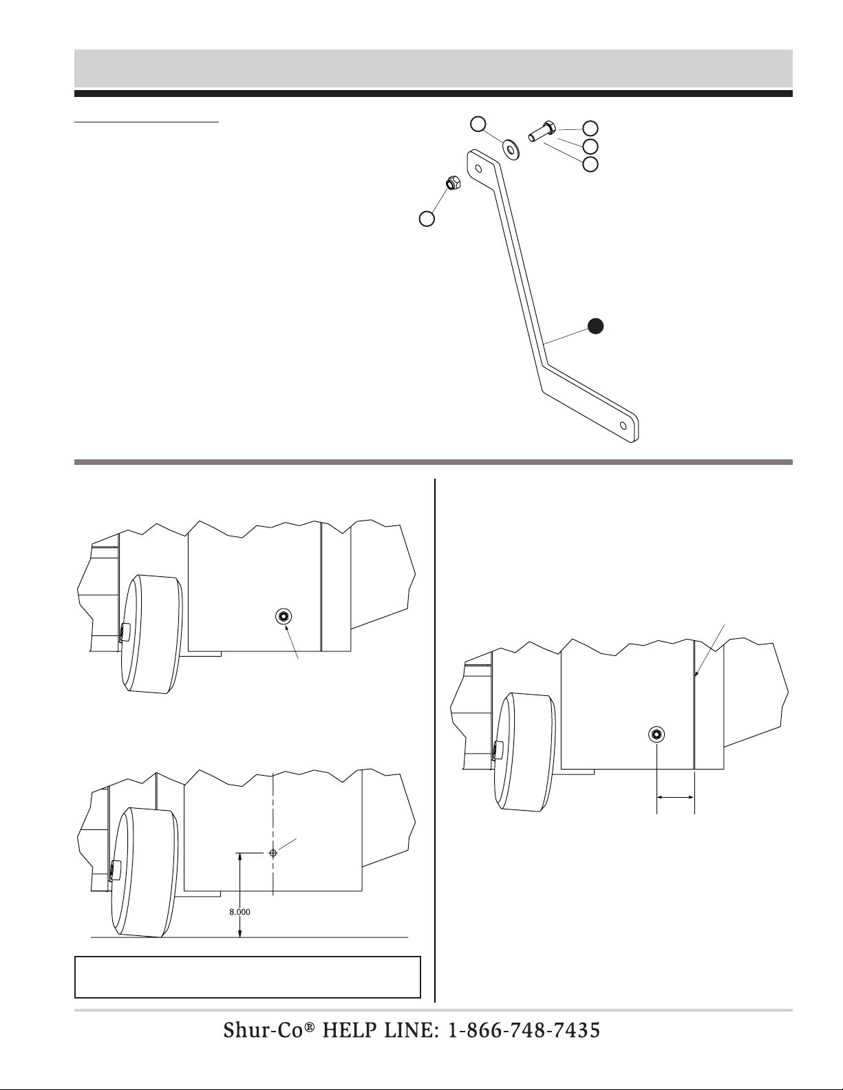
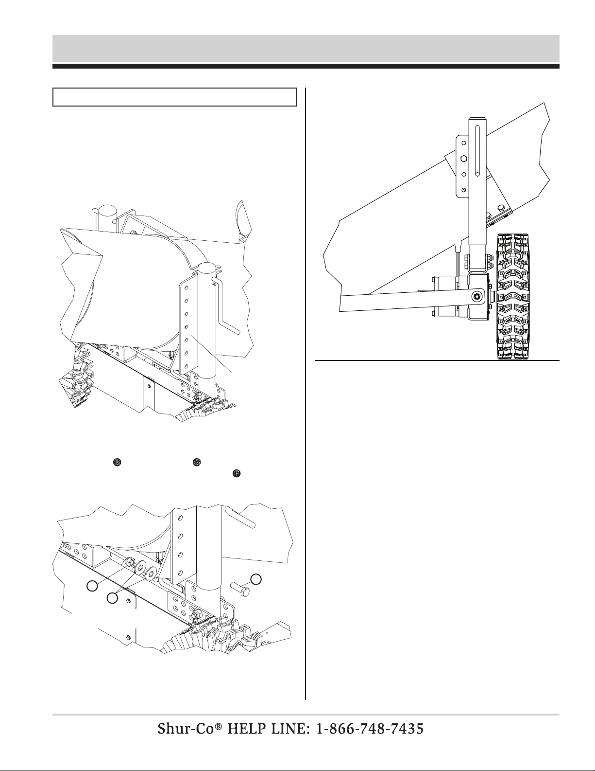
P/N 1127298 Rev. B Drive Brace Installation
2
STEP 1: Find existing transition box pivot bolt location.
If transition box does not have pivot bolt, locate and
drill a 1/2" hole approximately centered front-to-back
and 8" up from ground.
STEP 2: If box has ange, measure distance from ange to
pivot bolt hole.
• If no ange or ifdistance “A” is 3-1/2″ or greater,
continue to Step 3A.
• If ange is between 2-1/2″ and 3-1/2″, skip to Step
3B.
• If ange is less than 2-1/2″, skip to Step 3C.
Item Part # Description
1. 1127464 Drive Brace - 10″ to 11″
1127468 Drive Brace - 11″ to 12″
1127229 Drive Brace - 12″ to 13″
1127424 Drive Brace - 13″ to 14″
1127273 Drive Brace - 14″ to 15″
1127425 Drive Brace - 15″ to 16″
1127274 Drive Brace - 16″ to 17″
1127426 Drive Brace - 17″ to 18″
1127275 Drive Brace - 18″ to 19″
1128621 Drive Brace - 19" to 20"
1128622 Drive Brace - 20" to 21"
B. 1705920 Cap Screw - 1/2" x 1-1/2″
C. 1701042 Cap Screw - 1/2″ x 2″
D. 1704041 Cap Screw - 1/2″ x 2-1/2″
F. 1705913 Nylon Nut - 1/2″
G. 1705911 Flat Washer - 1/2″
F
GB
C
D
1/2"dia.
transition box
pivot bolt
flange
distance “a”
1
NOTE: Before drilling any holes, verify bolt will not interfere
with operation of swing auger.
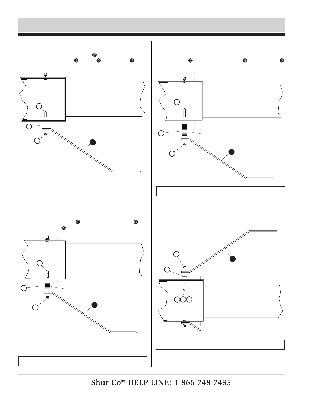
P/N 1127298 Rev. B
3
Drive Brace Installation -continued
STEP 3A: If distance “A” is greater than 3-1/2″ from ange or
if there is no ange, remove existing hardware. Drill
holes to accept 1/2″ bolt B, if needed. Secure drive
brace using bolt B, washer G and nylon nut F
. Hand
tighten nut.
STEP 3C: Distance “A” is less than 2-1/2″ from ange, remove
existing hardware. Drill holes in transition box to
accept 1/2″ bolt, if needed. Secure drive brace using
bolt D, 1″ stack of at washer G
, and nylon nut F
.
Hand tighten nut.
STEP 4: Repeat Step 3 on opposite side.
STEP 3B: If distance “A” is between 2-1/2″ and 3-1/2″ from
ange, remove existing hardware. Drill holes in transi-
tion box to accept 1/2″ bolt, if needed. Secure drive
brace using bolt C, 1/2″ stack of at washer G and
nylon nut F. Hand tighten nut.
NOTE: Measure stack of washers; thickness can vary.
NOTE: Measure stack of washers; thickness can vary.
NOTE: Use same bolt and washer stack on both sides.
C
C
G
G
F
B
G
F
1
1
1
1/2″stack
of washers
D
G
F
F
1
1″stack
of washers*
BD

P/N 1127298 Rev. B
4
Jack Installation
Item Part # Description
1. 1128470 Main Beam
2. 1127235 Jack 2-Hole
3. 1128578 Jack 2-Hole Dual
E. 1705914 Cap Screw - 1/2″ x 3-1/4″
F. 1705913 Nylon Nut - 1/2″
STEP 1: Remove bolt E and nylon nut Ffrom main beam.
STEP 2: Locate correct hole in jack bracket for tube size of
auger.
F
E
12
3
8″
8″
10″
10″
12″
12″
13″
13″
14″
14″
16″
16″
F
E
E
E
E
E
F
F
F
F
right side
left side
left side
install
right side
install
STEP 3A: While on level ground secure jack 2to main beam
with bolt E and nylon nut F. (For 8" to 13" auger
tubes.)
STEP 3B: While on level ground, secure jack 3to main beam
with bolt E and nylon nut F. (For 14" and 16" auger
tubes.)
2
3
2
3

P/N 1127298 Rev. B
5
Main Beam To Swing Auger Installation
Item Part # Description
1. 1127230 Wheel Counter-Clockwise
2. 1127234 Wheel Clockwise
3. 1127291 Tube Band Jack Mount - 8″
1127250 Tube Band Jack Mount - 10″
1127252 Tube Band Jack Mount - 12″
1127293 Tube Band Jack Mount - 13″
1127254 Tube Band Jack Mount - 14″
1127256 Tube Band Jack Mount - 16″
4. 1127282 Tube Band - 8″
1127246 Tube Band - 10″
1127247 Tube Band - 12″
1127283 Tube Band - 13″
1127248 Tube Band - 14″
1127249 Tube Band - 16″
5. For 8" to 13" Auger Tubes
6. For 14" to 16" Auger Tubes
B. 1705920 Cap Screw - 1/2″ x 1-1/2″
F. 1705913 Nylon Nut - 1/2″
G. 1705911 Flat Washer - 1/2″
L. 1705968 Lynch-Pin 5/16″ x 1-3/4″
STEP 1: Install wheels on main beam and secure with lynch
pin J.
STEP 2: Align main beam and jack with swing auger tube and
drive braces. Secure with at washers G and nylon
nuts F. Tighten nylon nuts F, then back nut off 1/4
turn so main beam can pivot at drive braces.
L
L
B
B
B
B
B
F
F
F
F
F
F
F
F
F
F
G
G
G
G
G
G
L
L
2
1
1
4
3
6
5
3
3
2
NOTE: 8" to 13" auger tube with right side jack installation is shown below. Left side installation is same, but jack will be on
opposite side of auger tube. For 14" and 16" auger tubes, jack will be on each side of auger tube.
NOTE: Before proceeding to Step 2, position main auger
tube as if lling a bin or silo.
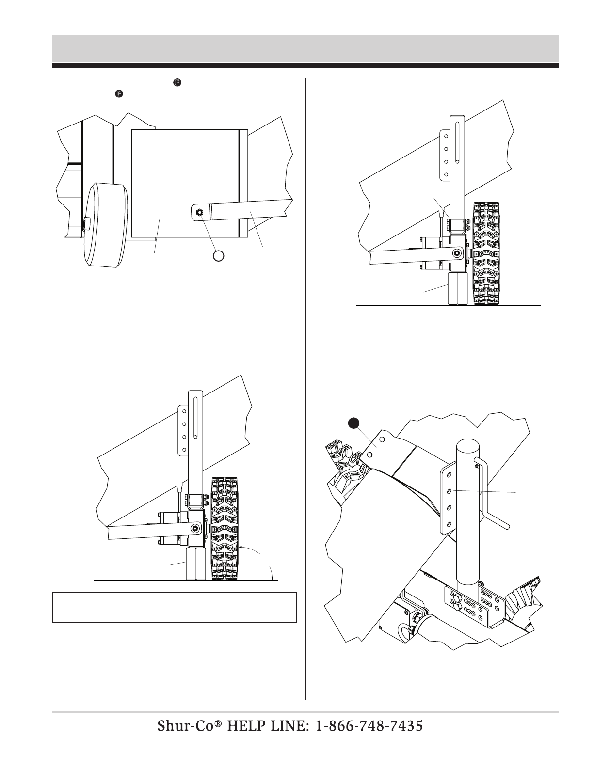
P/N 1127298 Rev. B
6
Main Beam To Swing Auger Installation -continued
STEP 3: Tighten nylon nuts F at transition box. Then back
nuts F off 1/4 turn so drive brace can rotate on bolt.
STEP 5: With drive wheels resting on ground, square main
beam assembly so jack is perpendicular to ground.
Placing a 5″ wooden block under main beam will help
determine correct position.
STEP 4: Repeat Step 3 on other side of transition box.
STEP 6: Turn jack handle until jack is in fully down position.
STEP 7: Place tube band jack mount on swing auger tube and
align with plate on jack. Turn handle on jack, raising
jack plate until hole in tube band jack mount is aligned
with hole in jack plate.
NOTE: Wood block may be constructed by ripping two 12″
2x6s to 5″wide and nailing or screwing together.
wood
block
transition box
pivot brace
F
90°
align
holes
jack fully
down
wood
block
3
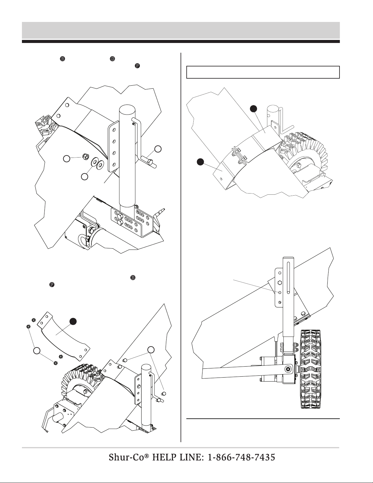
P/N 1127298 Rev. B
Main Beam To Swing Auger Installation -continued
7
STEP 8: Secure jack plate to tube band jack mount using hex
bolt B, two at washers G between tube band jack
mount and jack plate and nylon nut F. Tighten nylon
nut, then back off 1/4 turn.
STEP 9: Position tube band by tube band jack mount. Secure
bands together using hex bolts B and nylon nuts
F. Evenly tighten fasteners securing bands to swing
auger.
STEP 10: Both 14" and 16" auger tubes will use two tube band
jack mount bands.
STEP 10: Turn jack handle to bring main beam to fully up posi-
tion. Verify both wheels are off ground. If wheels do
not come off ground, you will need to move to next
lower hole in jack plate.
F
G
B
B
F
4
3
3
place both washers
between plates
adjust to lower
hole, if needed
NOTE: Second jack not shown for clarity of image.
P/N 1127298 Rev. B
8
NOTE: Next two steps for 14" and 16" augers only.
STEP 11: Lower main beam down to wooden blocks. Adjust left side
jack so it is extended to same length as righthand jack.
Adjust jack height until holes in jack plate and tube
band jack mount align. If holes will not align, match
drill a 1/2" hole in tube band jack plate using jack
plate as guide.
align or match
drill 1/2" hole
STEP 12: Secure jack plate to tube band jack mount using hex
bolt B, two at washers G between tube band jack
mount and jack plate and nylon nut F. Tighten nylon
nut, then back off 1/4 turn.
STEP 13: Remove wood block and lower drive wheels to ground.
F
G
B
place both washers
between plates
Main Beam To Swing Auger Installation -continued
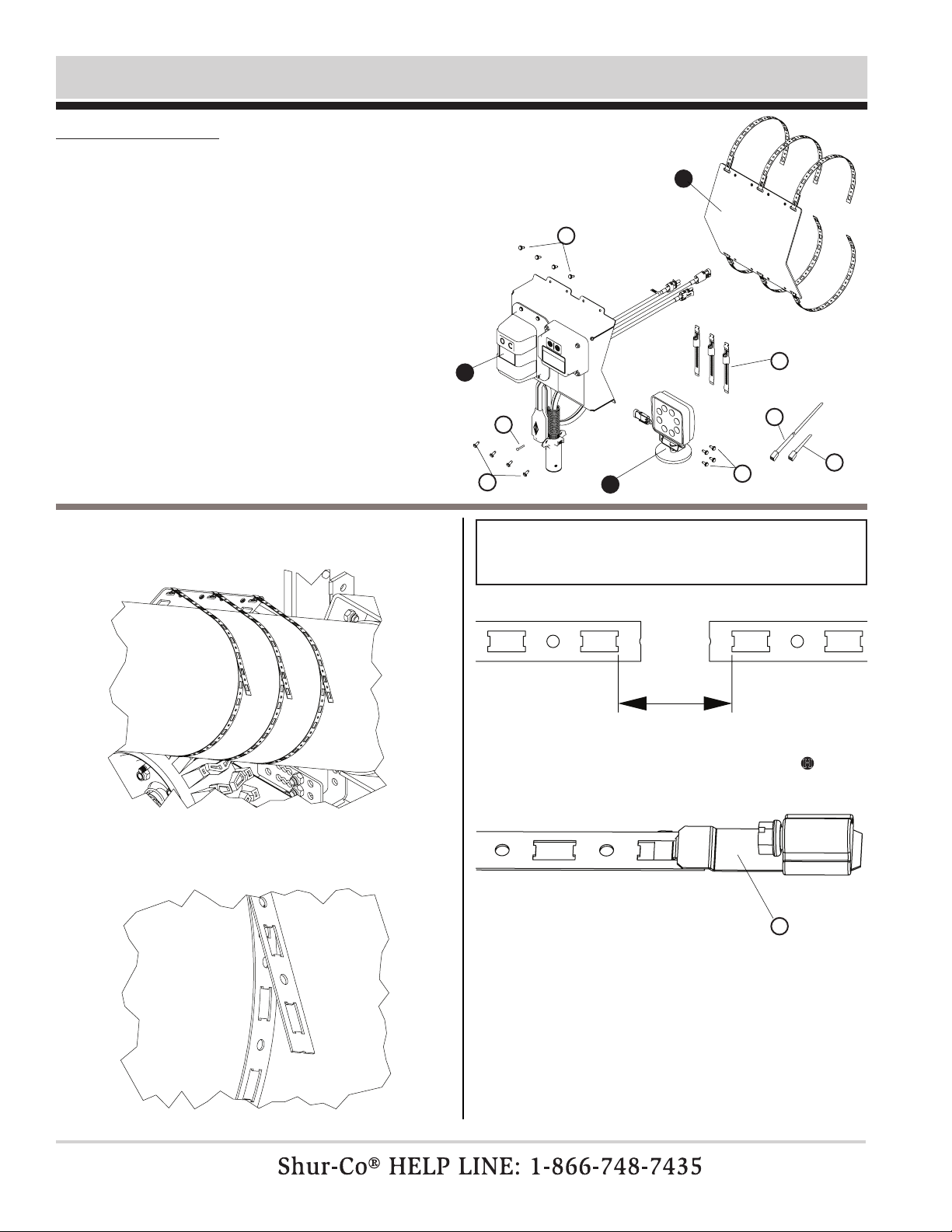
P/N 1127298 Rev. B
9
Control Box Installation
Item Part # Description
1. 1128570 Control Panel Mounting Plate
2. 1128576 Control Assembly SMART2™ w/SMART2™ LiteALL™
1128575 Control Assembly SMART3™ w/SMART3™ LiteALL™
3. 1128572 LiteALL™ w/Magnetic Mount
A. 1704308 Flanged Screw - #10 x 1/2″
H. 1706376 Hose Clamp Fastener Set
J. 1703231 Cable Tie - 8″
K. 1705977 Cable Tie - 60″
M. 1704751 Wire Harness Lock Pin
STEP 1: Place control panel mounting plate on auger tube and
wrap bands around tube so they overlap.
STEP 2: Trim top bands with an aviation snip at holes so new
end is approximately 1-1/2" above center line of tube.
STEP 3: Insert screw half of hose clamp fastener H into last
square of upper bands.
A
AAJ
K
H
H
M
1
2
3
4-1/2"
NOTE: Overlap is acceptable, but if bands do not overlap,
a max gap of 4-1/2" is acceptable between edges of two
closest square holes.
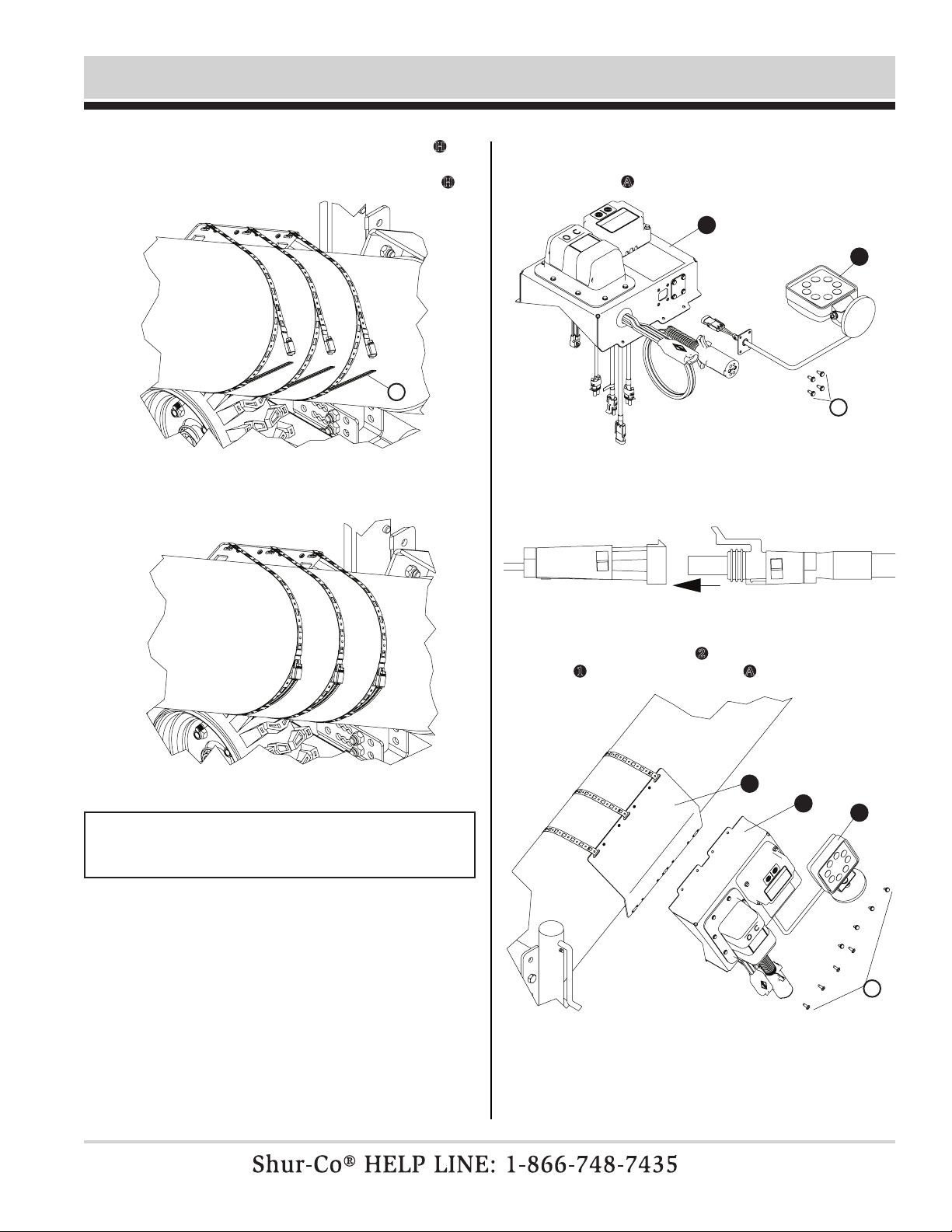
P/N 1127298 Rev. B
10
Control Box Installation -continued
STEP 4: Insert slotted half of hose clamp fashener Hinto
square hole of lower bands, approximately 3-1/5"
from end of screw half of hose clamp fastener H.
STEP 5: Insert end of slotted fastener into end of screw fastener
and tighten each of three bands.
STEP 6: Insert WeatherPack™ end of LiteALL™ into open
hole of bottom of control panel and secure with ange
screws A.
STEP 8: Mount control panel 2 to control panel mounting plate
1 with eight ange screws A.
STEP 7: Plug LiteALL™ into mini-module wire.
H
NOTE: Verify location of control pannel will not interfere with
storage of swing auger onto side of main auger tube. Adjust
accordingly, if necessary.
A
A
2
2
3
3
1
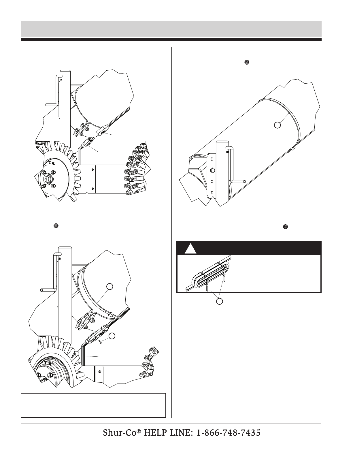
P/N 1127298 Rev. B
11
Control Box Installation -continued
STEP 11: Working up swing auger tube, gently pull SMART-
wire™ snug (under swing auger tube) and secure
with 60″ cable tie K at center of tube between rst
cable tie and discharge box.
STEP 12: Bind excess wire with 8″ cable ties J.
CAUTION
Do not cut SMARTwire™.
Bind excess wire with
cable ties.
!
K
J
STEP 9: Run SMARTwire™ from rear of control box under
swing auger tube and plug female end into male end.
STEP 10: Secure SMARTwire™ to auger tube using 60″ cable
tie K, leaving enough slack so auger hopper can be
raised off ground without putting tension on plug or tie.
K
leave slack,
see note
female
smartwire™
male
smartwire™
NOTE: Turn handle on jack so it is in fully extended position
to ensure enough slack in wire before securing with cable
ties.
M

P/N 1127298 Rev. B
12
Decal Installation
Item Part # Description
1. 1705998 Danger - Pinch Point
2. 1706000 Danger - Automatic Movement
STEP 1: Turn jack handle raising drive wheels off ground and
push swing auger so swing auger tube and main
auger tube are next to each other.
STEP 2: At location where tubes cross, install four Danger -
Pinch Point decals on both sides of tubes.
STEP 3: Place Danger - Automatic Movement decal on outside
of end and both sides of swing auger hopper.
1. Plug male 2-pole connector into female 2-pole connector on
tractor. Route SMARTwire™ so it will not be driven over.
2. Caution: Always verify path of swing auger is clear of obsta-
cles and people before operation.
3. Stand clear of path of swing auger. Use remote of control box
to activate motors and verify direction of travel. If swing auger
direction of travel is not correct, remove auger control cover
and switch green and yellow wires on solenoid.
4. When direction of travel has been veried, run swing auger in
both directions, verifying it moves freely and along intended
work path.
NOTE: If DriveMaxx™ wheels spin but do not move swing
auger, turn jack handle to lower wheels to increase tranction.
OPERATION INSTRUCTIONS
1
2
2
2
12
main auger tube
swing auger tube
11
Table of contents
Popular DC Drive manuals by other brands


GFA
GFA ELEKTROMAT SI 360.12 FU-80,00 installation instructions

Power Electronics
Power Electronics SD 500 Series manual

Inovance
Inovance Aonarch MD500L Series user guide

G-U
G-U ELTRAL K25 Installation and operating instructions

PR electronics
PR electronics 5203B manual

ETC
ETC F-Drive B-Box4 installation guide