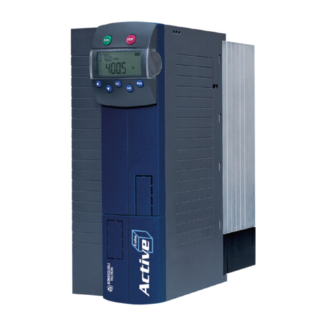
NORDAC PRO (SK 500P) – Users Manual for Frequency Inverters
4 BU 0600 en-2319
Table of Contents
1General.........................................................................................................................................................8
1.1 Device characteristics ........................................................................................................................9
1.2 Delivery ............................................................................................................................................12
1.3 Scope of delivery..............................................................................................................................12
1.4 Safety, installation and operating instructions..................................................................................16
1.5 Explanation of markings...................................................................................................................20
1.6 Warning information on the product .................................................................................................21
1.7 Standards and approvals .................................................................................................................22
1.7.1 UL and CSA approval.........................................................................................................22
1.8 Type code / nomenclature................................................................................................................23
1.8.1 Type plate...........................................................................................................................23
2Assembly and installation ........................................................................................................................25
2.1 Frequency inverter installation .........................................................................................................26
2.2 Braking resistor (BR)........................................................................................................................27
2.2.1 Electrical data for braking resistors.....................................................................................28
2.2.2 Dimensions of bottom-mounted braking resistor SK BRU5 ................................................29
2.2.3 Dimensions of chassis BR SK BR2 ....................................................................................29
2.2.4 Monitoring of the braking resistor .......................................................................................30
2.2.4.1 Monitoring with a temperature switch 30
2.2.4.2 Monitoring with current measurement and calculation 30
2.3 Chokes.............................................................................................................................................31
2.3.1.1 Input choke SK CI1-… 31
2.3.2 Output choke SK CO1 ........................................................................................................33
2.4 Line filter ..........................................................................................................................................34
2.4.1 Mains filter SK HLD ............................................................................................................34
2.5 Electrical Connection .......................................................................................................................35
2.5.1 Overview of connections ....................................................................................................36
2.5.2 Wiring guidelines ................................................................................................................38
2.5.3 Electrical connection of power unit .....................................................................................39
2.5.3.1 Electromechanical brake 40
2.5.3.2 Mains connection (PE, L1, L2/N, L3) 40
2.5.3.3 Motor cable (U, V, W, PE) 41
2.5.3.4 Braking resistor (B+, B-) 42
2.5.3.5 DC coupling (B+, DC-) 42
2.5.4 Electrical connection of the control unit ..............................................................................45
2.6 Colour and contact assignments for encoders .................................................................................51
2.7 RJ45 WAGO connection module .....................................................................................................53
3Options.......................................................................................................................................................54
3.1 Overview of option modules.............................................................................................................54
3.2 SK TU5-CTR ....................................................................................................................................56
3.2.1 Control keys........................................................................................................................56
3.2.2 Display................................................................................................................................57
3.2.2.1 Displays 57
3.2.2.2 Operation 57
3.2.2.3 Status displays 58
3.2.3 Control................................................................................................................................58
3.2.4 Parameterisation ................................................................................................................59
3.3 Frequency addition and subtraction via control boxes .....................................................................61
3.4 Connection of multiple devices to one parametrisation tool .............................................................61
4Commissioning .........................................................................................................................................62
4.1 Factory settings................................................................................................................................62
4.2 Selecting the operating mode for motor control ...............................................................................64
4.2.1 Explanation of the operating modes (P300) .......................................................................64
4.2.2 Overview of control parameter settings ..............................................................................66
4.2.3 Motor control commissioning steps ....................................................................................67
4.3 Minimum configuration of control connections .................................................................................68
4.4 Temperature sensors.......................................................................................................................69


