manuals.online logo
Brands
  1. Home
  2. •
  3. Brands
  4. •
  5. ETC
  6. •
  7. DC Drive
  8. •
  9. ETC F-Drive B-Box4 User manual

ETC F-Drive B-Box4 User manual

ETC Installation Guide
F-Drive B-Box4
Corporate Headquarters nMiddleton, WI, USA|+1 608 831 4116
Global Offices nLondon, UK|Rome, IT|Holzkirchen, DE|Paris, FR|Hong Kong|Dubai, UAE|Singapore
New York, NY|Orlando, FL|Los Angeles, CA|Austin, TX|©2023 Electronic Theatre Controls, Inc.
Web etcconnect.com |Support support.etcconnect.com |Contact etcconnect.com/contactETC
Trademark and patent info: etcconnect.com/ip |Third-party license agreement info:etcconnect.com/licenses
Product information and specifications subject to change.ETCintends this document to be provided in its entirety.
7148M2120RevBReleased 2023-11
Overview
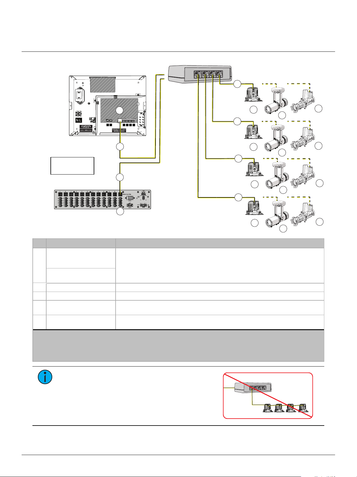
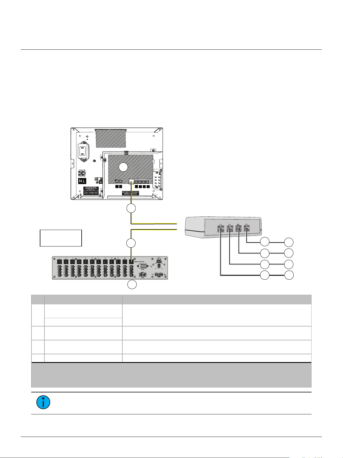
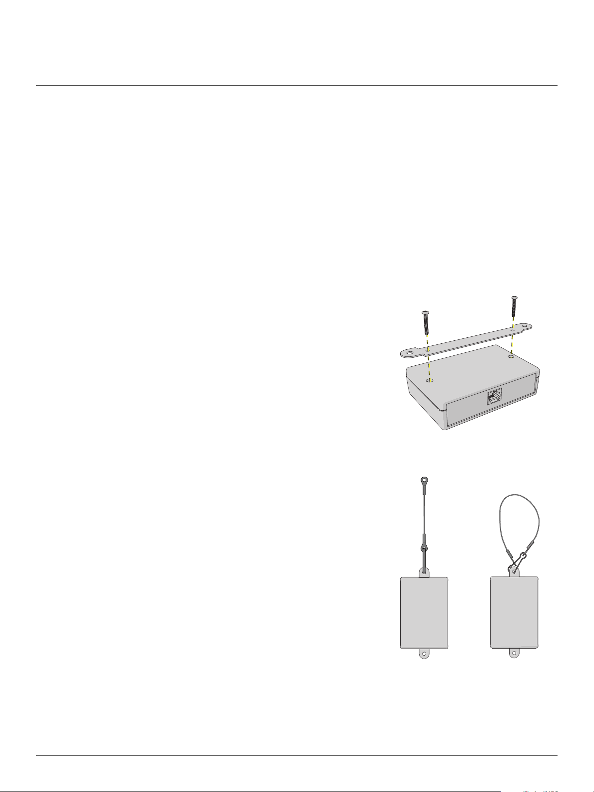
Thank you for purchasing an F-Drive Boomtabatty-Box4 (B-Box4). B-Box4 takes a single four-
channel RJ45 output from an F-Drive R12 output card or W1Driver and provides four separated
output channels to support a variety of F-Drive-compatible luminaires (listed below) or third-party
loads in star topology.
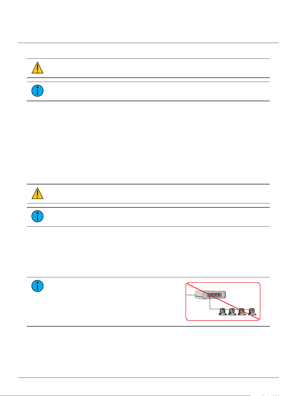
Note:
If you install a B-Box within an Emergency Lighting Circuit, follow NECmarking
requirements or local jurisdiction requirements.
Compatible Products
Luminaires
F-Drive-Compatible Luminaires with RJ45 Connectors
• Navis100 Fixed White and Fade to Warm luminaires
• Source Four Mini LED for F-Drive Fixed White luminaires
• Irideon FPZ and Irideon WLZfor F-Drive Fixed White luminaires
Note:
Navis RGBW luminaires are not compatible with B-Box4.
F-Drive-Compatible Luminaires with Molex Connectors
• ArcSystem Pro One-Cell Standard Fixed White or Fade to Warm
• ArcSystem Pro One-Cell Small Fixed White or Fade to Warm
• ArcSystem Pro One-Cell Micro Fixed White or Fade to Warm
Drivers
• F-Drive R12 Driver with CC-150Card or FTW-150Card, one B-Box4 per output card
• F-Drive W1CCDriver or W1FadetoWarmDriver, one B-Box4 per driver
Note:
W1CVDriver, W1 Chroma Driver, R12 ArcLamp150Card, R12 CV-150Card,
and R12 ChromaCard are not compatible with B-Box4.
F-Drive System Design Tool
The F-Drive System Design Tool (etcconnect.com/FDriveSysDesignTool) allows you to design an
F-Drive R12 rack unit or F-Drive W1Driver with different luminaires, breakout boxes, cable
lengths, and other system components.
LEDDimming Compatibility Database
The LEDDimming Compatibility Database (etcconnect.com/compatibility) is a searchable list of
devices that ETChas tested for compatibility with ETCdimming and control systems.
ETC Installation Guide
F-Drive B-Box4
F-Drive B-Box4 Page 2 of 11 ETC
Documentation for Compatible Products
The following documents are available at etcconnect.com/Products/Power-Controls/LED-Drivers/F-
Drive/Documentation.aspx:
•
F-Drive Series R12 Installation Manual
•
F-Drive Series W1 Installation Manual
•
F-Drive R12 and W1 Wiring Reference Guide
The following documents are available at etcconnect.com/Products/Architectural-Fixtures:
•
ArcSystem Navis 100 Installation Guide
•
Source Four Mini LED F-Drive Installation Guide
•
Irideon WLZ (F-Drive) Installation Guide
•
Irideon FPZ (F-Drive) Installation Guide
•
ArcSystem Pro D1 and D2 Series Drivers Installation Guide
for information about ArcSystem
Pro One-Cell luminaires
Features
• Input from F-Drive R12 or W1Driver
• Enables star topology wiring
• Preserves four separate channels of control from F-Drive R12 output card or F-Drive
W1Driver
• Connects to
‐F-Drive-compatible luminaires with RJ45 connectors, see
Connect F-Drive-Compatible
Luminaires with an FD-BBOX-4R on page 3
.
‐ArcSystem Pro One-Cell luminaires, see
Connect ArcSystem Pro One-CellLuminaires with
an FD-BBOX-4M on page5
.
‐Third-party loads, see
Connect Third-Party Loads with an FD-BBOX-4T on page6
.
ETC Installation Guide
F-Drive B-Box4
F-Drive B-Box4 Page 3 of 11 ETC
F-Drive Model B-Box Models
FD-BBOX-4R FD-BBOX-4M FD-BBOX-4T
F-Drive R12 with
CC-150Card
Four RJ45 outputs for
four F-Drive-compatible
luminaires with RJ45
connectors, one per
channel. For a list of
compatible luminaires,
see
F-Drive-Compatible
Luminaires with RJ45
Connectors on page1
.
Four Molex Mini-Fit
outputs for four
ArcSystem Pro
luminaires, one per
channel. For a list of
compatible luminaires,
see
F-Drive-Compatible
Luminaires with Molex
Connectors on page1
.
Four two-pin terminal
outputs for third-party
constant current loads.*
F-Drive W1CCDriver
F-Drive R12 with
FTW-150Card
Four RJ45 outputs for
four ArcSystem Navis
100 Fade to Warm
luminaires, one per
channel.
F-Drive
W1FadetoWarmDriver
*Total number of loads and number of loads per channel depends on the specifications of the third-party
loads. Visit the F-Drive System Design Tool at etcconnect.com/FDriveSysDesignTool to learn more, and
search the LEDDimming Compatibility Database at etcconnect.com/compatibility to see if your load is
compatible. If your load is not in the compatibility database, follow the instructions at the link above to
contact the ETC Applications Engineering department to arrange for compatibility testing.
Note:
Each of the four output channels of an R12 CC-150Card or W1CCDriver can be
configured independently to provide 200–700 mA drive current. See Configure the
Output Current on page11 and the
F-Drive Series R12 Installation Manual
or
F-Drive
Series W1 Installation Manual
for information on configuring the output current.
CAUTION: To avoid damage to equipment, use FD-BBOX-4M to connect
ArcSystem Pro One-Cell luminaires to your F-Drive Driver.
If you do not use FD-BBOX-4M, you must use the proper pinouts for each model
of ArcSystem Pro One-Cell luminaire. See the F-Drive Series R12 Installation
Manual or F-Drive Series W1 Installation Manual Appendix A, section "Connect
ArcSystem Pro One-Cell Luminaires to the Terminal Block Output."
Connect F-Drive-Compatible Luminaires with an FD-BBOX-4R
Connect up to four F-Drive-compatible luminaires with RJ45 connectors to an F-Drive with a
FD-BBOX-4R. Visit the F-Drive System Design Tool at etcconnect.com/FDriveSysDesignTool to learn
more.
Note:
Navis RGBW luminaires are not compatible with B-Box4.
Note:
If you install a B-Box within an Emergency Lighting Circuit, follow NECmarking
requirements or local jurisdiction requirements.
ETC Installation Guide
F-Drive B-Box4
F-Drive B-Box4 Page 4 of 11 ETC
SENSE
1 2 3 4
DMX
IN
DMX
THRU
MAINTAIN
B
B
Ch 4
Ch 3
Ch 2
Ch 1
FDR12FD
FD-BBOX-4R
B
B
FDW1CCD (-CE)/FDW1FTWD (-CE)
AC
A
D
E
C
D
E
B
B
C
D
E
C
D
E
Driver can be
W1 or R12
Description Notes
A
CC-150Card or
FTW-150Card installed in a
card slot of an F-Drive R12
The CC-150Card and W1CCDriver output constant current, adjustable from 200–700mA.
You must configure each channel of the driver to provide the correct current for the
connected luminaire. See
Configure the Output Current on page11
.
The FTW-150Card and W1FadetoWarmDriver are compatible with Navis100 Fade to Warm
luminaires.
W1CCDriver or
W1FadetoWarmDriver
B Category-type cable†You must use 0.25mm2(23AWG) or larger conductors in Category-type cable.
C ArcSystem Navis luminaires Fixed White or Fade to Warm depending on the W1Driver or R12 output card
DAlternative:Irideon for
F-Drive luminaires* Irideon FPZ for F-Drive or Irideon WLZ for F-Drive luminaires
EAlternative:Source Four Mini
LED for F-Drive luminaires*
*Irideon FPZ for F-Drive, Irideon WLZ for F-Drive, and Source Four Mini LED for F-Drive luminaires require an F-Drive R12
CC-150Card or W1CCDriver (non-emergency installations only).
†See
Electrical and Wiring Specification on page8
.
Note:The illustration is not drawn to scale. Loads are not shown on all outputs of the F-Drive R12 for clarity.
Note:
F-Drive-Compatible luminaires will not
function if they are daisy-chained from the output of
the B-Box.
FD-BBOX-4R
ETC Installation Guide
F-Drive B-Box4
F-Drive B-Box4 Page 5 of 11 ETC
Connect ArcSystem Pro One-CellLuminaires with an
FD-BBOX-4M
Connect up to four ArcSystem Pro standard, Small, or Micro luminaires to an F-Drive with a
FD-BBOX-4M. Visit the F-Drive System Design Tool at etcconnect.com/FDriveSysDesignTool to
learn more.
SENSE
1 2 3 4
DMX
IN
DMX
THRU
MAINTAIN
FDR12FD
FD-BBOX-4M
Ch 4
Ch 3
Ch 2
Ch 1
A
C
C
C
C
DDD
D
FDW1CCD (-CE)
A
B
B
Driver can be
W1 or R12
Description Notes
A
CC-150Card installed in
a card slot of an F-Drive
R12
The CC-150Card and W1CCDriver output constant current, adjustable from 200–700mA. You
must configure each channel of the driver to provide the correct current for the connected
luminaire. See
Configure the Output Current on page11
.
W1CCDriver
B Category-type cable* The cable from the RJ45 output of the driver to the input of the FD-BBOX-4M. You must use
0.25mm2(23AWG) or larger conductors in Category-type cable.
C
Use the cable attached
to the ArcSystem Pro
One-Cell luminaire
Extension cables are available. See the datasheets for ArcSystem Pro One-Cell luminaires at
etcconnect.com/Products/Architectural-Fixtures/Pro-One-Cell/Documentation.aspx.
DArcSystem Pro One-Cell
luminaire
ArcSystem Pro One-Cell (ARCP1), Pro One-Cell Small (ARCP1S), or Pro One-Cell Micro (ARCP1M);
White or Fade to Warm.
*See
Electrical and Wiring Specification on page8
.
Note:The illustration is not drawn to scale. Loads are not shown on all outputs of the F-Drive R12 for clarity.
ETC Installation Guide
F-Drive B-Box4
F-Drive B-Box4 Page 6 of 11 ETC
Connect Third-Party Loads with an FD-BBOX-4T
FD-BBOX-4T with an F-Drive constant current driver supports a wide variety of third-party loads.
Determining compatibility between these loads and your F-Drive product configuration is an
important step toward ensuring the success of a project. Visit the F-Drive System Design Tool at
etcconnect.com/FDriveSysDesignTool to learn more, and search the LEDDimming Compatibility
Database at etcconnect.com/compatibility to see if your load is compatible. If your load is not in
the compatibility database, follow the instructions at the link above to contact the ETC
Applications Engineering department to arrange for compatibility testing.
SENSE
1 2 3 4
DMX
IN
DMX
THRU
MAINTAIN
FD-BBOX-4T
Ch 4
Ch 3
Ch 2
Ch 1
FDW1CCD (-CE)
A
FDR12FD A
C
C
C
C
D
D
D
D
B
B
Driver can be
W1 or R12
Description Notes
A
CC-150Card installed in one card
slot of an F-Drive R12 The CC-150Card and W1CCDriver output constant current, adjustable from
200–700mA. You must configure each channel of the driver to provide the correct
current for the connected load.†
W1CCDriver
B Category-type cable* The cable from the output of the CC-150Card to the input of the FD-BBOX-4T. You
must use 0.25mm2(23AWG) or larger conductors in Category-type cable.
C0.2–1.5mm2(26–14AWG)Class 2
wire pair
D Third-party constant current loads See
W1CCDriver or CC-150Card Limits on page8
.
*See
Electrical and Wiring Specification on page8
.
†See
Configure the Output Current on page11
.
Note:The illustration is not drawn to scale. Loads are not shown on all outputs of the F-Drive R12 for clarity.
Note:
Do not bus/bridge channels in an attempt to exceed the individual channel limits.
ETC Installation Guide
F-Drive B-Box4
F-Drive B-Box4 Page 7 of 11 ETC
Prepare to Install a Breakout Box
Installation Requirements
• 0°C–40°C (32°F–104°F) ambient room temperature
• 5%-95% non-condensing ambient humidity
Parts and Tools
The following supplies are not provided:
• Optional Breakout Box Mounting Kit (ETCpart number 7148K1018) to secure the B-Box4
with a lanyard
• Two M5 (#10) screws or other mounting hardware as needed
• Phillips screwdriver for installation of the mounting plate or lanyard
• FD-BBOX-4T: wire stripping and cutting tool and flatblade screwdriver as needed
Note:
Installation must follow all national and local codes for electrical equipment.
Note:
Mounting hardware and installation location must support the weight of the
breakout box (0.16 kg [0.36 lb])and all cable required for installation.
Ceiling-Mount Considerations
The minimum hole diameter to insert a B-Box4 through an installed ceiling is 95mm (3-3/4in) with
input and output cables disconnected.
System Components
Each B-Box4 requires one F-Drive R12 output card or W1Driver that is compatible with the load
type. Consult the table on
page 3
to determine the appropriate driver type for your installation.
Visit the F-Drive System Design Tool at etcconnect.com/FDriveSysDesignTool to learn more.
ETC Installation Guide
F-Drive B-Box4
F-Drive B-Box4 Page 8 of 11 ETC
Electrical and Wiring Specification
Connector/
Port Name B-Box4 Model Connector/
Port Type Wire Range/Specifications Strip Length Torque
Rating
IN All RJ45
You must use 0.25mm2
(23AWG) or larger
conductors in Category-
type cable.*†
Terminate to T568B
standard.
CH1, CH2,
CH3, and
CH4
FD-BBOX-4R RJ45
You must use 0.25mm2
(23AWG) or larger
conductors in Category-
type cable.*†
Terminate to T568B
standard.
FD-BBOX-4M Molex Mini-
Fit
Use the fixture cable attached to the ArcSystem Pro One-
Cell luminaire. Extensions are available.†See the datasheet
for your luminaire.
FD-BBOX-4T Two-pin
terminal
0.2–1.5mm2(26–14AWG)
using the provided two-
terminal connectors. Follow
Class 2 wiring methods.
7 mm (1/4in) 0.5–0.6N•m
(4.4–5.3in-lb)
*Not all Cat5 or Cat6 cables meet this requirement.
†Maximum supported wire length between F-Drive compatible luminaires and F-Drive drivers is 100m
(328ft) for each luminaire. This is the limit for the total length of cable between each luminaire and the
F-Drive driver, including the Category-type cable between the driver and the B-Box and the cable
between the B-Box and the luminaire.
Note:
Cable bundling limitations apply to F-Drive B-Box4 Class 2 output cables. For
more information about maximum number of four-pair cables in a bundle, see
NFPA702020 National Electrical Code, table 725.144.
W1CCDriver or CC-150Card Limits
A W1CCDriver or F-Drive CC-150Card is capable of providing up to 48VDC and 700mA per
channel.Power loss in cables varies by cable length and type. The power loss in cables on both
sides of the B-Box4 contributes to the load per channel. For guidance on load limits for channels,
output cards, or systems, visit the F-Drive System Design Tool at
etcconnect.com/FDriveSysDesignTool.
Note:
Do not bus/bridge channels in an attempt to exceed the individual channel limits.
ETC Installation Guide
F-Drive B-Box4
F-Drive B-Box4 Page 9 of 11 ETC
Install a Breakout Box
Mount the B-Box4
B-Box4 can be surface-mounted to any structure capable of supporting its weight using the
included mounting plate or hung from a support structure using the mounting plate and tether
(not included).
Mounting Accessories
• Surface-mount:use the mounting plate only (included; ETCpart number 7148A3051)
• Hang:use the 457mm (18in) tether in the breakout box tether kit (not included; ETCpart
number 7148K1018)
Install the Mounting Plate
In order to surface-mount the B-Box4 or attach the tether, you must install the mounting plate.
1. Set the B-Box4 on a flat work surface.
2. Using the Phillips screwdriver, remove the two screws on
the bottom of the B-Box4.
• Save these screws. They hold the top and the bottom
of the B-Box4 together and they will be used to attach
the mounting plate.
3. Attach the mounting plate to the bottom of the B-Box4
using the screws you removed in the previous step.
Surface-Mount the B-Box4
To surface-mount the B-Box4, attach it to the mounting surface
with two M5 (#10) screws.
Hang the B-Box4
The tether has an eye at both ends and one J-hook spring clip.
You can use it in two ways:clip the tether to the B-Box4
mounting plate and attach the eye on the free end of the tether
to a surface, or loop the tether around a support structure and
clip the hook onto the B-Box4 mounting plate and the free end
of the tether.
The tether is not shown to scale; it is 457mm (18in) long.
ETC Installation Guide
F-Drive B-Box4
F-Drive B-Box4 Page 10 of 11 ETC
Connect the Input
CAUTION: Do not coil excess Category-type cable.
Note:
You must use 0.25mm2(23AWG) or larger conductors in Category-type cable.
Not all Cat5 or Cat6 cables meet this requirement.
1. Verify that the B-Box4 input is from an F-Drive R12 output card or W1Driver that is
compatible with your luminaire or load. See the table on
page 3
for compatible driver and
load types.
2. Plug one end of a Category-type cable into the four-channel RJ45 output of an appropriate
F-Drive R12 output card or W1Driver.
3. Plug the other end of the Category-type cable into the B-Box4 RJ45 "IN" port.
Connect Luminaires or Loads to a B-Box4
Complete the steps below for your model of B-Box4 to connect luminaires or loads to the four
outputs.
FD-BBOX-4R
CAUTION: Do not coil excess Category-type cable.
Note:
You must use 0.25mm2(23AWG) or larger conductors in Category-type cable.
Not all Cat5 or Cat6 cables meet this requirement.
1. Plug one end of a Category-type cable into the "CH1", "CH2", "CH3", or "CH4" output of
the FD-BBOX-4R.
2. Plug the other end of the Category-type cable into the "IN" port of the luminaire.
3. Repeat steps 1 and 2 to connect one luminaire per output with one Category-type cable per
luminaire.
4. Configure each output of the F-Drive R12 output card or W1Driver to provide the correct
current for your luminaires. See
Configure the Output Current on page 11
.
Note:
F-Drive-Compatible luminaires will not
function if they are daisy-chained from the output of
the B-Box.
FD-BBOX-4R
ETC Installation Guide
F-Drive B-Box4
F-Drive B-Box4 Page 11 of 11 ETC
FD-BBOX-4M
1. Plug the Molex connector from an ArcSystem Pro One-Cell standard, Small, or Micro
luminaire cable into the "CH 1", "CH 2", "CH 3", or "CH 4" output of the FD-BBOX-4M.
2. Repeat step 1 to connect one ArcSystem Pro One-Cell luminaire per Molex output.
3. Configure each output of the F-Drive R12 output card or W1Driver to provide the correct
current for your luminaires. See
Configure the Output Current on page 11
.
FD-BBOX-4T
1. Prepare the wires for the provided screw-terminal plugs (ETC part J3388-F).
• See
Electrical and Wiring Specification on page8
for the wire gauges accepted by the
screw-terminal connectors and strip the wires according to the strip length listed.
2. Connect the loads to outputs "CH 1", "CH 2", "CH 3", and "CH4"using the two-terminal
plugs.
a. See the image above for polarity of the output terminals.
b. Wire the positive and negative wires from the load to separate terminals on the plug,
securing the terminal screws onto the wires.
c. Tug gently on the wires to ensure they are secure.
d. Insert the screw-terminal plug into the "CH1", "CH2", "CH3", or "CH4" receptacle.
3. Configure each output of the F-Drive R12 output card or W1Driver to provide the correct
currents for your luminaires or loads. See
Configure the Output Current below
.
Configure the Output Current
CAUTION: Setting the driver card to output more current than the
manufacturer's recommended fixture driver current may reduce the lifetime of
the fixtures or cause damage to the fixtures.
Each channel of the CC-150Card or W1CCDriver has adjustable output current and is factory-set
to output 200mA. You must configure each channel of the driver to provide the correct current
for the connected luminaire. For more information about configuring the output current, see the
F-Drive Series R12 Installation Manual
or
F-Drive Series W1 Installation Manual
at
etcconnect.com/Products/Power-Controls/LED-Drivers/F-Drive/Documentation.aspx.
Individual Channel Control
The load connected to each B-Box4 output responds to an individual output channel 1, 2, 3, or 4
from the F-Drive R12 output card or W1Driver. See the F-Drive Device Package Help in
ETCConcert for details on configuration with ETCConcert. See the
F-Drive Series R12 Installation
Manual
or the
F-Drive Series W1 Installation Manual
for details on RDMconfiguration of the
output channels.
Compliance
For current and complete compliance information, view the product datasheets at
etcconnect.com/Products/Power-Controls/LED-Drivers/F-Drive/Documentation.aspx. For complete
product documentation, including compliance documentation, visit etcconnect.com/products.

Other manuals for F-Drive B-Box4

1

Other ETC DC Drive manuals

ETC F-Drive R12 Series User manual

ETC

ETC F-Drive R12 Series User manual

ETC F-Drive Series User manual

ETC

ETC F-Drive Series User manual

ETC ArcSystem Pro D4 Series User manual

ETC

ETC ArcSystem Pro D4 Series User manual

Popular DC Drive manuals by other brands

ABB DCS 400 manual

ABB

ABB DCS 400 manual

elero VariEco L RH Operating and assembly instructions

elero

elero VariEco L RH Operating and assembly instructions

Rockwell Automation Allen Bradley Kinetix 7000 2099-BM06-S Design guide

Rockwell Automation

Rockwell Automation Allen Bradley Kinetix 7000 2099-BM06-S Design guide

Danfoss VLT CDS 302 Troubleshooting

Danfoss

Danfoss VLT CDS 302 Troubleshooting

Masterflex I/P Series quick start guide

Masterflex

Masterflex I/P Series quick start guide

Electro-Voice ID60D-8 Specifications

Electro-Voice

Electro-Voice ID60D-8 Specifications

SOMFY S&SO-RS100 io instructions

SOMFY

SOMFY S&SO-RS100 io instructions

Intelligent Motion Systems Excellence in Motion IM805H operating instructions

Intelligent Motion Systems

Intelligent Motion Systems Excellence in Motion IM805H operating instructions

KLEE Drive MS Series manual

KLEE

KLEE Drive MS Series manual

Johnson Controls VFD66 Series user guide

Johnson Controls

Johnson Controls VFD66 Series user guide

MicroPAP Easy Motion SD-808 user manual

MicroPAP Easy Motion

MicroPAP Easy Motion SD-808 user manual

SERAD IMD / 1 installation guide

SERAD

SERAD IMD / 1 installation guide

ABB ACS355 UL 4X quick start guide

ABB

ABB ACS355 UL 4X quick start guide

Siemens SIMATIC FM 453 manual

Siemens

Siemens SIMATIC FM 453 manual

Alpha AS600M Series manual

Alpha

Alpha AS600M Series manual

Wittenstein Alpha LP Series operating manual

Wittenstein Alpha

Wittenstein Alpha LP Series operating manual

ABB DCS800 Service manual

ABB

ABB DCS800 Service manual

Masterflex L/S MFLX77200-12 operating manual

Masterflex

Masterflex L/S MFLX77200-12 operating manual

manuals.online logo
manuals.online logoBrands
  • About & Mission
  • Contact us
  • Privacy Policy
  • Terms and Conditions

Copyright 2025 Manuals.Online. All Rights Reserved.