manuals.online logo
Brands
  1. Home
  2. •
  3. Brands
  4. •
  5. Shure
  6. •
  7. Amplifier
  8. •
  9. Shure SE20 User manual

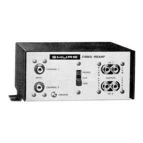
Shure SE20 User manual

Other Shure Amplifier manuals

Shure M267 User manual

Shure

Shure M267 User manual

Shure UA844+ Series User manual

Shure

Shure UA844+ Series User manual

Shure UA845 User manual

Shure

Shure UA845 User manual

Shure RK183PK User manual

Shure

Shure RK183PK User manual

Shure SR109 Operation manual

Shure

Shure SR109 Operation manual

Shure MX1BP User manual

Shure

Shure MX1BP User manual

Shure SHA900 User manual

Shure

Shure SHA900 User manual

Shure M267 User manual

Shure

Shure M267 User manual

Shure SHA900 User manual

Shure

Shure SHA900 User manual

Shure UA830 User manual

Shure

Shure UA830 User manual

Shure SR105 Operation manual

Shure

Shure SR105 Operation manual

Shure A900-PM-38IN User manual

Shure

Shure A900-PM-38IN User manual

Shure Microflex RK100PK User manual

Shure

Shure Microflex RK100PK User manual

Shure Microflex RK100PK User manual

Shure

Shure Microflex RK100PK User manual

Shure SR10 Operation manual

Shure

Shure SR10 Operation manual

Shure M64 User manual

Shure

Shure M64 User manual

Shure UA830 User manual

Shure

Shure UA830 User manual

Shure ILP-1 User manual

Shure

Shure ILP-1 User manual

Shure M267 User manual

Shure

Shure M267 User manual

Shure WA400 User manual

Shure

Shure WA400 User manual

Shure AXIENT AXT630 User manual

Shure

Shure AXIENT AXT630 User manual

Shure RK100PK User manual

Shure

Shure RK100PK User manual

Shure UA834WB User manual

Shure

Shure UA834WB User manual

Shure UA834 User manual

Shure

Shure UA834 User manual

Popular Amplifier manuals by other brands

Magnat Audio EDITION FOUR Owner's manual/warranty document

Magnat Audio

Magnat Audio EDITION FOUR Owner's manual/warranty document

Inter-m PA-2000A Operation manual

Inter-m

Inter-m PA-2000A Operation manual

Yamaha TX6n owner's manual

Yamaha

Yamaha TX6n owner's manual

Peavey TNT 150 user guide

Peavey

Peavey TNT 150 user guide

Bosch LBB 1903/10 Installation and user instructions

Bosch

Bosch LBB 1903/10 Installation and user instructions

Avocent Emerge DA1200D Installer/user guide

Avocent

Avocent Emerge DA1200D Installer/user guide

Redgum RGi35 operating instructions

Redgum

Redgum RGi35 operating instructions

Cambridge Audio AXA25 user manual

Cambridge Audio

Cambridge Audio AXA25 user manual

Alpine MRP-M200 owner's manual

Alpine

Alpine MRP-M200 owner's manual

Technical Pro H1502UrBT user manual

Technical Pro

Technical Pro H1502UrBT user manual

FMS EMGZ307 operating manual

FMS

FMS EMGZ307 operating manual

Racal Instruments 5601 user manual

Racal Instruments

Racal Instruments 5601 user manual

Valcom V-1094A Technical specifications

Valcom

Valcom V-1094A Technical specifications

Cambridge Audio 851D user manual

Cambridge Audio

Cambridge Audio 851D user manual

QSC 3800 Specifications

QSC

QSC 3800 Specifications

NAD C300 owner's manual

NAD

NAD C300 owner's manual

Rotel RMB-1077 owner's manual

Rotel

Rotel RMB-1077 owner's manual

Peavey Monitor 300 Series operating guide

Peavey

Peavey Monitor 300 Series operating guide

manuals.online logo
manuals.online logoBrands
  • About & Mission
  • Contact us
  • Privacy Policy
  • Terms and Conditions

Copyright 2025 Manuals.Online. All Rights Reserved.

monaural source to one channel
of
the
SE20,
the
SE20
input should be shunted with a
47,000
ohm resistor
or the high frequency trimmer should be readjusted for
proper high frequency equalization.
Outputs:
Output terminals appear on the rear panel as
shown in Figure
C.
Outputs are balanced and designed
to feed a
150
ohm
or
600
ohm line.
REAR PANEL
FIGURE
C
Channel Level Controls:
These controls are located on
the front panel designated as “Channel A Level” and
“Channel
B
Level.” They are used to adjust the overall
operating level of the
SE20
and to balance the individual
levels of the two channels.
Response Trimmers:
To
allow for balancing the
response of the two channels
of
a stereo cartridge,
or
of two monaural cartridges, high and low frequency
response trimmers are provided for each channel. Figure
D
shows the location of these controls and Figure
E
shows the range and character
of
the response change
obtainable.
LOW
FREQUENCY
TRIMVER
HIGH
FREQUENCY TRIMMER
t20
fl
-
110
z
w
(0
0
go
Lz
w
$-I0
a
_I
w
Lz
-20
20
50
100
1,000
10,000
20,000
FREQUENCY
IN
HERTZ
TYPICAL EFFECT OF RESPONSE TRIMMERS
FIGURE
E
220
Volt Operation:
The power transformer may be
restrapped for operation with
220
volt
A.C.
supply.
To
make this change, see instructions
on
schematic
for
revising power transformer connections.
Guarantee:
This Shure product is guaranteed in normal
use to be free,from electrical and mechanical defects
for a period
of
one year from the date
of
purchase.
Please retain proof of purchase date. This guarantee
includes all parts and labor.
Shipping Instructions:
Carefully repack the unit and
return
it
prepaid to the factory. If outside the United
States, return the unit
to
your dealer
or
Authorized
Shure Service Center for repair. The unit will be re-
turned to you prepaid.
1
RESPONSE TRIMMERS
SIDE VIEW (COVER REMOVED)
FIGURE
D
I
jlfiTSklM,
15KHZ-R23
30HZ
-
R25
3.
ALL RESISTORS
112
WATT 59 CARBON COMPOSITION
UNLESS SHOWN. POTENTiOiETERS
20%
TOLERANCE.
2.CHANNEL
"n"
IS
SHOWN, 4.ALL NON -ELECTROLYTIC CAPACITORS
IN
MFD.
10%
CHANNEL'B"
IS
IDENTICAL AND
'100
VOLTS
OR
MORE UNLESS SHOWN.
TO CHANNEL "A': ELECTROLYTIC CAPACITORS SHOWN IN MFDXVOLTS
(TOLERANCE,-I0
f50
UNLESS SHOWN).
MODEL
SE20
STEREO TRANSCRIPTION PREAMPLIFIER SCHEMATIC