--
-
WA400 ANTENNA AMPLIFIER/SPLITTER FOR WIRELESS MICROPHONES
GENERAL
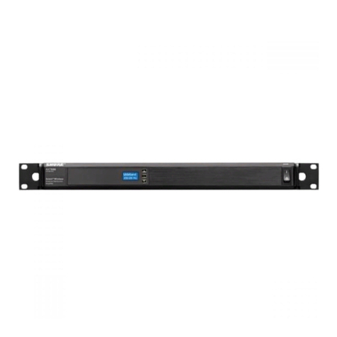
The Shure WA400 is a two-input, two-channel, eight-output
Antenna AmplifierISplitter permitting use of only two antennas
with as many as four diversity wireless microphone systems or
eight non-diversity systems. To compensate for any insertion
loss, the WA400 amplifies the wireless transmitter signals, and
feeds them to their respective wireless microphone receivers.
Forapplicationswhere multiplewireless microphonesare used,
theWA400 removestheclutter andextracablingassociatedwith
requirementsfor oneantenna (orantenna pair) permicrophone.
The WA400 is designed for rack mounting and is supplied
with rack-mount brackets.Eightrfcablesaresupplied toconnect
the Splitter to the wireless microphone receivers. Power to the
Splitter (120Vac) isderivedfrom thefurnished Shure PS20Pow-
er Supply (optional PS2OE for 230 Vac).
When planning a multiple microphone installation, keep in
mind that each microphone must transmit on a different fre-
quency and that frequencies must be selected in accordance
with system characteristics. Contact your Shure dealer for fur-
ther assistance.
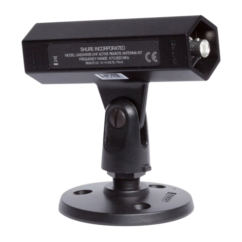
The WA400 is intended for use with the Shure Model WA380
Half-Wave Antennas and Model WA420 Extension Coaxial
Cables or other high-quality coaxial cables.
INSTALLATIONAND SETUP
I
Selecttheappropriate antenna(s):
A. Three versions of the WA380 Half-Wave Antenna are
available, depending onthefrequency bandinwhich the
selected wireless systems operate. For optimum per-
formance, choose the:
1.
WA380A for frequencies from 169to 185 MHz
2.
WA380B for frequencies from 185to 200 MHz
3. WA380C for frequencies from 200 to 216 MHz.
B.
If
wirelessfrequencies inusearenotrestrictedto asingle
band, usetheWA380B. However,when usingnon-diver-
sity wireless receivers, group receivers into two bands
if possible, and choose the antennas suitable for those
bands.
I1
Installthe system:
A. Locate the WA400 in a rack or on a flat surface.
1. To mount the WA400 in a standard 19-inch equip-
ment rack, remove the single screw on each side of
theunit,positionthesuppliedmounting bracketsover
the holes, and secure the brackets with the two re-
moved screws and the two supplied screws.
2. To mount the WA400 on a surface, attach the four
supplied adhesive bumpers to the bottom corners of
the unit.
B. Connect the power.
Connect the PS20 Power Supply to an appropriate
120
Vac circuit (orPS20Eto 230Vac) andattach itscon-
centricconnectortothe powerjack onthe back panelof
the WA400. The green Power LED on the WA400 front
panel will illuminate to indicatethat the unit is powered.
C. Connect and mount the antennas.
1. Connect each antennato the WA400 by meansof the
6.1 m (20
ft)
WA420 ExtensionCable.
2. Locate and mount the antennas remotely as de-
scribed inthe instructionsheet for the WA380 Anten-
na. Useeither the mounting bracket suppliedwith the
antenna or a Shure Model A57 Swivel Adapter (or
equivalent)fortheantennamountif astandard micro-
phone stand is used to support the antenna.
3. For optimum reception, fully extend all telescoping
sections of the antenna, and make sure that the ex-
tended antenna is vertical.
D. Connect the receivers.
1. Usethe supplied rf cablesto connectthe AntennaIn-
putsofthe receiversto the
RF
Outputs of the WA400.
2. When using non-diversity receivers,if the rf frequen-
cies can begrouped intotwo bands, connect the re-
ceivers associated with the antennachosen for band
A to the WA400 Outputs for band A. Do the same for
band B.
Copyright
1990,
Shure BrothersInc.
27A8234
(JK)
Printed
in
U.S.A
