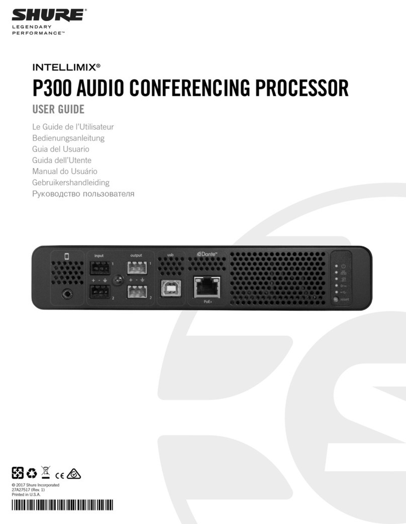
Shure DFR22AZ User manual

User Guide
©2009, Shure Incorporated
27A8869 (Rev. 3)
Printed in U.S.A.
DFR22AZ
Audio Processor
with Feedback Reduction
DFR22C
带有反馈消减的音频处理器
DFR22K
DFR22J
フィードバックの減少を
用い る可聴周波プ ロ セ ッ サー

2
English
! IMPORTANT SAFETY INSTRUCTIONS !
1. READ these instructions.
2. KEEP these instructions.
3. HEED all warnings.
4. FOLLOW all instructions.
5. DO NOT use this apparatus near water.
6. CLEAN ONLY with dry cloth.
7. DO NOT block any ventilation openings. Install in accordance with the manu-
facturer's instructions.
8. DO NOT install near any heat sources such as radiators, heat registers, stoves,
or other apparatus (including amplifiers) that produce heat.
9. DO NOT defeat the safety purpose of the polarized or grounding-type plug. A
polarized plug has two blades with one wider than the other. A grounding type
plug has two blades and a third grounding prong. The wider blade or the third
prong are provided for your safety. If the provided plug does not fit into your out-
let, consult an electrician for replacement of the obsolete outlet.
10. PROTECT the power cord from being walked on or pinched, particularly at plugs,
convenience receptacles, and the point where they exit from the apparatus.
11. ONLY USE attachments/accessories specified by the manufacturer.
12.
13. UNPLUG this apparatus during lightning storms or when unused for long periods of
time.
14. REFER all servicing to qualified service personnel. Servicing is required when the
apparatus has been damaged in any way, such as power-supply cord or plug is dam-
aged, liquid has been spilled or objects have fallen into the apparatus, the apparatus
has been exposed to rain or moisture, does not operate normally, or has been
dropped.
15. DO NOT expose the apparatus to dripping and splashing. DO NOT put objects filled
with liquids, such as vases, on the apparatus.
16. The MAINS plug or an appliance coupler shall remain readily operable.
17. The airborne noise of the apparatus does not exceed 70dB (A).
18. Apparatus with CLASS I construction shall be connected to a MAINS socket outlet
with a protective earthing connection.
19. To reduce the risk of fire or electric shock, do not expose this apparatus to rain or
moisture.
20. Do not attempt to modify this product. Doing so could result in personal injury
and/or product failure.
USE only with a cart, stand, tripod, bracket, or table
specified by the manufacturer, or sold with the
apparatus. When a cart is used, use caution when
moving the cart/apparatus combination to avoid
injury from tip-over.
This symbol indicates that dangerous voltage constituting a
risk of electric shock is present within this unit.
This symbol indicates that there are important operating and
maintenance instructions in the literature accompanying this unit.
WARNING:
Voltages in this equipment are hazardous to life. No user-serviceable parts inside. Refer all servicing to qualified service personnel. The
safety certifications do not apply when the operating voltage is changed from the factory setting.
WARNING: This product contains a chemical known to the State of California to cause cancer and birth
defects or other reproductive harm.

3
English
DESCRIPTION
The DFR22 Audio Processor with Feedback Reduction is a 2-input, 2-output digital audio processor. It is designed to equalize sound system re-
sponse, provide dynamics processing and alignment delay, and automatically detect and control acoustic feedback. A built-in 2 X 2 matrix mixer
allows either or both inputs to be routed to either or both outputs, with additional controls for levels and polarity.
The DFR22 is ideal for installed sound reinforcement applications, such as houses of worship, theaters, and meeting facilities. It is also a powerful
setup tool in live music applications. Using the DFR22's drag-and-drop graphical user interface, processors can be placed anywhere in the signal
path.
DFR22 Features
1. Shure's patented digital feedback reduction algorithm:
• Now includes stereo DFR processing capability
• New Auto Clear mode clears dynamic filters after a preset
change or power cycle. Dynamic filters can be automatically re-
moved after a specified number of hours.
2. Configurable signal path with drag and drop Windows interface.
Includes graphic and parametric EQ, up to 10 seconds of delay,
compression, limiting, gating, automatic gain control, ducking, and
a fully configurable two-way crossover.
3. Phoenix and XLR connectors for each input and output
4. Compatible with USB to serial port converters.
5. Front and back panel RS232 ports:
• 3-pin Phoenix connector on back panel.
• DB9 connector on front panel; requires only TX, RX, and GND
to be connected.
6. Three pre-loaded presets:
• Preset 1: Two mono 16 filter DFRs.
• Preset 2: A stereo 16 filter DFR.
• Preset 3: A mono 16 filter DFR on each input. Each input is rout-
ed to each output.
7. Preset selector and indicator for up to 16 presets
8. Control input pins for setting up remote preset, volume, and mute
controls
PACKING LIST
• Power Cable
• 5-pin DIN ShureLink Cable
• 4 Rackmount Screws with Nylon Washers
• Five 3-Pin Block Connector Terminals (for audio input/output
and RS-232 communication)
• One 6-pin Block Connector Terminals (for control inputs)
• One DFR22 Software CD-ROM and Online User Guide
REQUIREMENTS
Power Requirements
• 100-240 Vac, 50/60 Hz
• 45 W maximum
Computer Requirements
• 20 MB of hard drive space
• CD ROM drive
• RS-232 serial port and cable, or approved USB-to-Serial port
adapter*
• VGA monitor with 640 x 480/256 color, or higher resolution
• Mouse or other pointing device
NOTE:Processor speed and memory requirements vary, depending
on the version of Windows and number of background applications
you are running. Operating the DFR22 software simultaneously with
programs such as SIA-Smaart®or Gold Line TEF‘requires a faster
processor and more RAM. The chart below lists the minimum require-
ments for running the DFR22 software with no other applications--
including virus protection, firewall, instant messaging, or email--in the
background.
*Most USB-to-serial port adapters work well with the DFR22. To see the latest list of fully approved adapters, visit http://www.shure.com/mixers/models/dfr22.asp
SOFTWARE INSTALLATION
1. Insert supplied CD into your CD-ROM drive and follow the
on-screen instructions.
2. If installation does NOT start automatically, click on the [Start]
button the Windows taskbar and select [Run...] from the pop-up
menu.
3. Type [D:/setup}, where “D” is your CD-ROM drive letter.
4. Click OK and follow the on-screen instructions.
USING THE DFR22 SOFTWARE
Instructions for the DFR22 software are available in PDF format on the
CD-ROM included with the system, or on the Shure web site at
www.shure.com.
NOTE: Register this product by filling out and mailing the
enclosed registration card, or register online at the Shure web
site (www.shure.com). Registration allows you to receive
information about software updates as they become available.
Windows Version Processor Speed RAM
98, Second Edition Pentium 166 MHz 48 MB
NT Pentium 233 MHz 64MB
ME Pentium 300 MHz 64 MB
2000 Professional Pentium 300 MHz 96 MB
XP Professional, Home Pentium 300 MHz 128 MB

4
English
OVERVIEW
Front Panel
DFR22 FRONT PANEL
FIGURE 1
1. INPUT/OUTPUT Level Meters:
•
CLIP.
Illuminates at 3 dB below clipping level.
•
0 VU
.
+4 dBu, -10 dBV; software selectable
. 0 dB is equal to +4
dBu by default. If the input or output sensitivity is changed to -10
dBV using the DFR22 software, 0 dB equals -10 dBV.
•
–20 dB.
Illuminates when the signal meets or exceeds the indi-
cated level.
•
MUTE.
Illuminates when input or output is muted.
2. DFR Filter LEDs. Illuminate when individual feedback filters are
active. When a filter changes or is added, an LED flashes, then
stays on.
3. AUTO CLEAR Buttons and LEDs. Press and release these but-
tons to configure Auto Clear mode for each channel. Press them
again to activate Auto Clear. When an Auto Clear LED illuminates,
Auto Clear is active on its corresponding channel.
4. PRESS TO LOCK / HOLD TO CLEAR Button and LEDs. Press
this button to lock filters at their current values. Holding this button
down will reset all feedback filters, even if they are locked. The
LED lights to indicate that the lock is active.
5. BYPASS DFR FILTERS Button and LEDs. Press these buttons
to suspend feedback reducer operation and remove feedback fil-
ters from the audio path. When a Bypass LED illuminates, feed-
back reduction is bypassed on the corresponding channel.
Bypass does not affect other processors (such as equalizers,
delay, limiters, etc.).
6. LOAD Button. Press this button to activate a selected preset.
7. PRESET Indicator. Shows the number of the currently active
preset. Blinks to show the number of the other presets in the
DFR22 when pressing the SELECT buttons.
8. SELECT Buttons. Press to scroll through the presets stored in
the DFR22.
9. COMM LED. Flashes in unison with the feedback filter LEDs
when the detector is deploying a new filter or changing an existing
one, and also blinks whenever the unit is communicating with a
connected computer.
10. RS232 Port. Connects the DFR22 to a computer.
11. POWER LED. Illuminates when 100-240 VAC power is applied to
the DFR22.
Back Panel
DFR22 REAR PANEL
FIGURE 2
1. Power Connector. Connects to 100-240 VAC power.
2. Shure Link Interface. Allows linking of up to 16 Shure Link
devices, which may be accessed by a computer.
3. 3-Pin RS-232 Port. Connects the DFR22 to a computer. For use
with DFR22 software and control systems. Refer to the Computer
Connections section.
4. CONTROL IN Pins. Use control input pins for remote control of
preset switching, muting, and gain. Refer to the Control Pin Con-
nections section.
5. DIP Switches. Use Switches 1-4 to select a Shure Link Device
ID. Use Switch 5 to lock or unlock front panel controls. Refer to
the Front Panel Lockout section for information on locking front
panel controls.
6. Output Connectors (Phoenix). These active, cross-coupled,
balanced outputs can be used with balanced or unbalanced
inputs. They can be switched between +4 dBu/-10 dBV line-level
operation, using the DFR22 software. Refer to the Audio Connec-
tions section.
7. Output Connectors (XLR). These active, cross-coupled, bal-
anced outputs can be used with balanced or unbalanced inputs.
They can be switched between +4 dBu/-10 dBV line-level opera-
tion using the DFR22 software. Refer to the Audio Connections
section.
8. Input Connectors (Phoenix). These active balanced inputs can
be used with balanced or unbalanced outputs. They cannot be
used simultaneously with an XLR connector for the same input.
They can be switched between +4 dBu/-10 dBV line-level opera-
tion using the DFR22 software. Refer to the Audio Connections
section.
9. Input Connectors (XLR). These active balanced inputs can be
used with balanced or unbalanced outputs. They cannot be used
simultaneously with a Phoenix connector for the same input. They
can be switched between +4 dBu/-10 dBV line-level operation
using the DFR22 software. See Audio Connections section for
more information.
???? ?????? ??? ?????????
????? ?????? ??????????
??????? ???

5
English
DEFAULT PRESETS
The DFR22 comes with three factory-configured presets. Although a
computer is required to configure the DFR22's equalizers, dynamics
processors, delays, and crossover, you can use the DFR22 “out of the
box” as an automatic feedback reducer, without connecting it to a com-
puter.
Preset 1: Provides two independent feedback reducers. The audio
signal going to Input 1 is analyzed and filtered by a feedback reducer
using up to 16 notch filters, and is then routed to Output 1. Input 2 is
analyzed by another feedback reducer and then routed to Output 2. On
the front panel, Row A of the DFR Filters and controls is assigned to
the feedback reducer on Input 1; Row B is assigned to the feedback
reducer on Input 2.
Preset 2: Provides a stereo feedback reducer. Signal going into
each input is analyzed independently, but the feedback reducer ap-
plies the same notch filters to each channel. As with Preset 1, Row A
of the DFR filters and controls on the front panel is assigned to the
feedback reducer on Input 1; row B is assigned to the feedback reduc-
er on Input 2. Because the feedback reducers always apply the same
filters to both channels, the DFR filter indicators and controls are
linked.
Preset 3: Similar to Preset 1, except both inputs are routed to both
outputs.
FRONT PANEL CONTROL FUNCTIONS
Auto Clear
By default, the DFR22 saves all feedback filters during a preset
change or power cycle. However, you can configure the device to au-
tomatically remove dynamic feedback filters and changes to the depth
of fixed feedback filters, according to parameters that you specify.
Each time the DFR22 detects a feedback frequency, it assigns that fre-
quency to one of the filters. By default, the first eight frequencies are
assigned to fixed filters, and the second eight are assigned to dynamic
filters. Both types of filters can deepen if feedback reoccurs at the
same frequency. The frequency of a fixed filter will not change unless
you manually clear all of the filters. However, if all filters are in use and
an additional feedback frequency is detected, the DFR22 replaces the
oldest existing dynamic filter with a new filter at a new frequency.
Establishing the Auto Clear Function. To establish the Auto Clear
function, proceed as follows:
NOTE: The procedure for setting up the Auto Clear function using the
front panel controls differs slightly from the procedure in the DFR22
Windows software.
1. Ring out the sound system to set any feedback filters that you
want to be a permanent part of the system equalization.
2. Press the Auto Clear button on the DFR22 front panel. The Auto
Clear button will blink. Auto Clear will automatically re-designate
any engaged filters as fixed and the rest as dynamic. For exam-
ple, if you have five filters set, Auto Clear will designate those as
fixed and will designate the remaining 11 filters as dynamic.
3. The preset indicator will display a flashing [-h]. If you want Auto
Clear to work automatically after a certain number of hours, you
must use the Preset Select buttons to set the number of hours (1
to 99). Each filter has its own timer, starting from the time it is set
or changed. If you leave the preset indicator at [-h], Auto Clear will
only work on a preset change or power cycle.
4. Press either the LOAD button or the AUTO CLEAR button again.
The AUTO CLEAR LED will glow steadily.
5. When a preset is changed, or if power is turned off and on, the
DFR filters will return to the state they were in when Auto Clear
was engaged. If a number of hours was specified, each dynamic
filter and change to the depth of each fixed filter will be removed
that many hours after it is set.
Disengaging the Auto Clear Function. To disengage the Auto Clear
function, press the AUTO CLEAR button again. The Auto Clear LED
will go out, and the number of fixed filters and dynamic filters will reset
to eight of each type.
NOTE: Holding the clear button down while Auto Clear is engaged
will only clear the dynamic filters.
Press to Lock / Hold to Clear
Pressing these buttons locks the filters at their current values. If Auto
Clear is not engaged, holding them down for three seconds resets all
filters. If Auto Clear is engaged, holding them down only resets dynam-
ic filters. When the PRESS TO LOCK/ HOLD TO CLEAR LEDs are il-
luminated, the Lock function is engaged and no filters can be added or
changed. Also, the Auto Clear timer is suspended.
Bypass DFR Filters
Pressing the DFR BYPASS button suspends the feedback reducer op-
eration and bypasses existing feedback filters. It does NOT affect any
other processors. When the DFR BYPASS LED illuminates, the feed-
back reducer is disengaged.
Changing Presets
The Preset Indicator on the front panel displays the number of the ac-
tive preset. You can scroll through all presets stored in the device By
pressing the arrow keys on the preset selector. When you select a pre-
set number, the display blinks. If you press the LOAD button within five
seconds, the device will make the selected preset the new Live preset.
If you do not press the LOAD button, the preset will not change and the
display will return to the original Live preset.
The preset indicator and controls are also used for setting the number
of hours after which each dynamic filter is removed when engaging
Auto Clear.
Front Panel Lockout
When this DIP switch is in the “Unlock” position, all front panel controls
are enabled. When it is in the “Lock” position, all front panel controls
are disabled. However, all front panel indicators still function and show
the state of each parameter.
You can override this DIP switch using the DFR22 software and indi-
vidually enable or disable each button on the front panel of the DFR22.
Access to the DFR22 via a computer can only be disabled by setting
the appropriate security level through the DFR22 software.

6
English
DFR22 Theory
Feedback Reduction
No sound system (microphones + mixing/signal processing + power amplifiers/loudspeakers + room acoustics) has an absolutely flat frequency
response. When the level of a sound system is increased, the frequencies at which peaks occur will be the first to exceed the feedback threshold.
The DFR22 attenuates these frequencies, flattening the response of the sound system. The system can then operate at a higher overall level.
The DFR22 includes Shure's patented Adaptive Notch Filter algorithm that can discriminate between feedback and non-feedback sounds. When
this algorithm detects feedback, it inserts a shallow, narrow filter into the audio path, reducing gain at the frequency that is feeding back. (See
Figure 3.) This filter is called a notch filter, since it affects a narrow section of the audio spectrum. If the feedback does not stop, the filter depth is
increased. By default, filters in the DFR22 are deployed as HIGH Q filters. As a High Q filter gets deeper, its Q increases up to a Q of 101 (1/70th
of an octave). Using the DFR22 software, you can also set filters to deploy as LOW Q. Low Q filters affect a slightly wider range of frequencies by
maintaining a Q of 14.42 (1/10th of an octave) as they deepen. By default, the DFR22 can insert up to 16 notch filters per channel to reduce feed-
back.
The DFR22's feedback reduction algorithm can be used as a tool during system setup and for peace of mind against unexpected feedback. When
setting up a sound system with the DFR22, you can ring out the system by slowly raising the gain while talking into the microphones until the first
frequency begins to feed back. The DFR22 will automatically insert a notch filter to attenuate that frequency. Once the system stops feeding back,
you can further raise the level and repeat the process for additional frequencies. Typically, you can raise the gain 3 - 9 dB above the level at which
feedback first occurred. You should leave some filters available to catch feedback that might occur later, when the sound system is in use.
EFFECTS OF NOTCH FILTER ON FREQUENCY RESPONSE
FIGURE 3
DFR22 Limitations
The DFR22 (or any other feedback reduction processor) will not let you to increase gain beyond the physical limits of the sound system. In most
cases, the point of diminishing returns is reached once 5 to 8 notch filters have been set. This is because there are usually only a few dominant
peaks in a system's frequency response (Figure 4A). In most cases, you can expect a 6 to 9 dB improvement in gain-before-feedback. When you
are ringing out a system and notice that many frequencies feed back simultaneously, even when you increase the gain slowly, you have reached
the point of diminishing returns. If the system still has insufficient gain before feedback at this point, other changes must be made to the sound
system, such as changing the placement of the microphones and/or loudspeakers.
FREQUENCY RESPONSE OF AN UNEQUALIZED SOUND SYSTEM
FIGURE 4
RACK MOUNTING THE DFR22
Mount the DFR22 in any standard 19-inch audio equipment rack, using
the supplied screws. Refer to Figure 5.
NOTE: Avoid mounting wireless equipment and power amplifiers directly
above or below the DFR22. Additional rack mount supports may be
necessary for mobile installations.
RACK MOUNTING THE DFR22
FIGURE 5
MEASURED FREQUENCY RESPONSE WITH PEAK MEASURED FREQUENCY RESPONSE WITH NOTCH FILTER ADDED
= Feedback Threshold
Figure 4A Figure 4B
Use notch filters to lower peaks Lower overall system gain

7
English
POWER AND INITIALIZATION
Power Mains Connections
Use the supplied power cable to connect the DFR22 Audio Processor
to an active 100-240 Vac power source, as shown in Figure 6. The
Power LED on the front panel will glow green when power is applied.
NOTE: The DFR22 Audio Processor is designed to operate
continuously. Therefore, there is no power on/off switch.
DFR22 POWER CONNECTION
FIGURE 6
INITIALIZATION
Once power is applied, the DFR22 Audio Processor takes approxi-
mately 5 seconds to initialize. When initialization is complete, the In-
put/Output LEDs will flash, as shown in Figure. The DFR22 is ready to
use once the LEDs stop flashing.
DFR22 INITIALIZATION
FIGURE 7
AUDIO CONNECTIONS
NOTE: Audio will pass from the inputs to the outputs, even if it has not yet
been configured through the computer interface.
CAUTION: DO NOT connect equipment to both the Phoenix
and XLR connectors of the same input or output at the same
time. Doing so could damage the equipment.
Wiring Connectors
INPUT/OUTPUT CONNECTOR WIRING DIAGRAMS
FIGURE 8
??
Power LEAD
RCA
XLR
Female)
XLR
Male)
Phone Plug
(Unbalanced)
Phone Plug
(Balanced)
Phone Plug
(Unbalanced)
Phone Plug
(Balanced)
RCAXLR
Male)
Phone Plug
(Unbalanced)
Phone Plug
(Balanced)
RCA
DFR22 PHOENIX CONNECTOR OUTPUTS / INPUTS
12 3
DFR22 XLR CONNECTORS (OUTPUT) DFR22 XLR CONNECTORS (INPUT)
XLR
(Female)

8
English
12 dB and 18 dB Output Pads
Each DFR22 output has a 12 dB pad and an 18 dB pad that can be
engaged through the software interface. Use these pads when con-
necting the DFR22 to lower-level inputs. They cannot be used to pre-
vent clipping at the output stage of the DFR22
NOTE: The Output meters indicate the signal level present at the
digital-to-analog converters. The 12 and 18 dB pads act upon the
signal after the digital-to-analog converters, so the meters do not
reflect the pads.
COMPUTER CONNECTIONS
RS-232 Connections
Connect the COM port on your computer to the 9-pin RS-232 connec-
tor on the front panel of the DFR22, shown in Figure 9, using a
male-to-female serial cable. Pin outs for a 9-pin RS-232 cable are
shown in Figure 10 and listed in Table 1.
NOTE: Only the TX, RX, and GND pins need to be connected in order
to communicate with the DFR22.
You can also connect a computer or control system to the 3-pin
RS-232 Phoenix connector on the back panel of the DFR22, as shown
in Figure 11.
IMPORTANT: You CANNOT connect two PCs to the DFR22 at the
same time. However, you CAN connect an AMX or Crestron system
and a PC to the DFR22 at the same time.
RS-232 SERIAL PORT CONNECTION
FIGURE 9
RS-232 CABLE PINOUTS
FIGURE 10
PHOENIX RS-232 SERIAL PORT CONNECTION
FIGURE 11
Table 1. RS-232 PIN OUTS
Shure Link Network
Up to 16 Shure Link devices, including the DFR22, DFR11EQ,
DP11EQ, P4800, and UA888, can be linked and controlled from one
computer. Using 5-pin DIN cables, connect the Shure Link IN and
Shure Link OUT of each device, as shown in Figure 12.
NOTE: The last device in the chain MUST be connected to the first
device (the one connected directly to the computer) to form a
loop.
SHURELINK NETWORK CONNECTIONS
FIGURE 12
9-PIN FEMALE
TO COMPUTER
9-PIN MALE
TO DFR22
DFR22 9–PIN RS-232
FEMALE CONNECTOR
COMPUTER 9-PIN RS-232
MALE CONNECTOR
DFR22 COMPUTER PIN NO.
-- -- 1
TX RX 2
RX TX 3
-- DTR 4
GND GND 5
-- DSR 6
-- RTS 7
-- CTS 8
-- -- 9
RS-232
SHURELINK OUT
SHURELINK IN
RS-232
DEVICE ID # 0
DEVICE ID # 1
DEVICE ID # 2

9
English
DIP Switch Settings for Networked Devices
Assign each Shure Link device a unique Device ID Number, using DIP
Switches 1-4, as shown in Figure FIGURE 13. Refer to Table 2 for De-
vice ID settings.
IMPORTANT: Each Shure Link device MUST have a unique Device ID
number.
DIP SWITCH SETTINGS FOR NETWORKED DEVICES
FIGURE 13
Table 2. DEVICE ID SETTINGS
*Default setting.
CONTROL PIN CONNECTIONS
The control pins on the back of the DFR22 connect to switches, potentiometers, and controller hardware. The Control Input pins can be used to
change presets, adjust gain, and mute channels.
NOTE: Use the DFR22 software to configure the control pins so that they match the attached control hardware. You can also use the software to
assign minimum and maximum gain values for each control, as well as the gain increment for up/down volume control buttons. Refer to the Control
Pin section of the Online Help or to the Online User Guide.
Determining Control Pin Allocations
When allocating control pins, you should first determine which pins are
to be used for preset control. Any remaining pins can then be used to
adjust gain or to mute channels. The number of pins needed for preset
control depends on the type of control hardware used, as well as the
number of presets.
The following methods can be used to allocate control pins:
•
One-to-One:
Use one pin for each preset, starting at Pin 1, and
proceeding toward the right. You MUST use consecutive pins.
Connect momentary or latching switches.
•
Shure DRS10 Switch:
Use Pin 1 for up to 10 presets.
•
Custom Switch:
Use Pin 1 for up to 10 presets.
•
Binary:
Use the pin numbers listed in Table 3. Connect latching
switches.
Table 3. BINARY CONTROL PIN ALLOCATION
Preset Control Connections
Various types of control hardware can be connected to the Control In-
put pins, as shown in Figure . When properly configured, the DFR22
changes to the appropriate preset in response to the switch. Resistor
values for custom switches and the Shure DRS10 are listed in Table 4.
NOTE: The total resistance of the cable run, from the switch to the
DFR22, should be less than 100 ohms. Two-conductor, unshielded cable,
such as a Belden 8442, is recommended.
Table 4. CUSTOM SWITCH RESISTOR VALUES
WIRING CONTROL-INPUT PINS FOR PRESET CONTROL
FIGURE 14
Device
ID
DIP Switch Device
ID
DIP Switch
1 2 3 4 1 2 3 4
0DN DN DN DN 8DN DN DN UP
1UP DN DN DN 9UP DN DN UP
2DN UP DN DN 10 DN UP DN UP
3UP UP DN DN 11 UP UP DN UP
4DN DN UP DN 12 DN DN UP UP
5UP DN UP DN 13 UP DN UP UP
6DN UP UP DN 14 DN UP UP UP
7UP UP UP DN 15* UP UP UP UP
Number of Presets Pin Numbers
2 1
41 and 2
81–3
16 1–4
PRESET RESISTOR VALUE
197 kΩ– ∞ Ω
244–60 kΩ
326–32 kΩ
417–20 kΩ
511.3–13.6 kΩ
67.8–9.3 kΩ
75.2–6.3 kΩ
83.3–4.1 kΩ
91.9–2.5 kΩ
10 0.63–1.1 kΩ
One-to-one Configuration
(Each pin represents one preset)
Binary Configuration
Shure DRS10 or Custom Switch Configuration*

10
English
Mute Control Connections
For mute control, use either a latching switch or a momentary switch.
The total resistance of the cable run from the switch to the DFR22
should be less than 100 ohms.
Figure 15 shows an example of how to connect either a latching switch
or a momentary switch to the Control Input pins to mute an input or an
output.
MUTE CONTROL PIN CONNECTIONS
FIGURE 15
Gain Control Connections
For gain control, use either a potentiometer or two momentary switch-
es (one for gain up and one for gain down). If you want to have multiple
sets of gain controls acting on the same inputs or outputs, use momen-
tary switches connected in parallel. Figure 16 shows a typical connec-
tion between a potentiometer and the Control Input pins. Figure 17
shows a typical connection between two momentary switches and the
Control Input pins.
When using a potentiometer, the total resistance of the cable run
should be less than 100 ohms.
When using momentary switches, the total resistance of the cable run
should be less than 100 ohms.
NOTE: As supplied, the DFR22 control pins are configured for use with
a 10 Kohm audio taper potentiometer. However, you can use the Po-
tentiometer Calibration Wizard in the DFR22 software to configure the
DFR22 for use with any 10 Kohm, 20 Kohm, 50 Kohm, or 100 Kohm
linear or audio taper potentiometer.
GAIN CONTROL PIN CONNECTIONS USING A
POTENTIOMETER
FIGURE 16
GAIN CONTROL PIN CONNECTIONS USING SWITCHES
FIGURE 17
AMX / Crestron Control Connections
You can connect an AMX or Crestron controller to the back panel
RS-232 port, using a Phoenix connector, or to the front panel RS-232
port, using a DB-9 connector. In either case, you only need to connect
three wires: send, receive, and ground. See page 8 for the pinout of
the RS-232 ports.
To access AMX/Crestron control codes for the DFR22, visit the DFR22
web page at http://www.shure.com/mixers/models/DFR22.asp.
Switch
(momentary or latching)
Ground
10kWPotentiometer
(Audio Taper)
Switch
(momentary)
Ground
Switch
(momentary)

11
English
SPECIFICATIONS
Frequency Response
20 Hz to 20 kHz ±1 dB
Dynamic Range
110 dB minimum, A-weighted, 20 Hz to 20 kHz
Sampling Rate
48 kHz
Digital-to-Analog, Analog-to-Digital Conversion
24 bit
Impedance
Input: 10 kΩ
Output: 120 Ω
Input Clipping Level
+24 dBu minimum
Output Clipping Level
+24 dBu
+12 dBu (with 12 dB pad)
+6 dBu (with 18 dB pad)
Total Harmonic Distortion
< 0.05%, +4 dBu, 20 Hz to 20 kHz
Propagation Delay from Input to Output
<1.5 ms
Polarity
Input to output: non-inverting (inverting optional)
Operating Voltage
100-240 Vac, 50/60 Hz (auto-switching), 1 A, maximum
Maximum Power Drain
45W
Temperature Range
Operating: -7°to 49°C (19°to 120°F)
Storage: -29°to 74°C (-20°to 165°F)
Dimensions
482.6 mm x 247.7 mm x 44.4 mm (19 in. x 9.75 in. x 1.75 in.)
(See Figure FIGURE 18)
Weight
2.83 kg (6.25 lbs)
Furnished Accessories
Power Cable (DFR22).................................................. 95A8389
Power Cable (DFR22E) ............................................... 95A8247
5-pin DIN Shure Link Cable ......................................... 95A8676
Hardware Kit ...............................................................90AJ8100
12 Block Connector Terminals, 3-pin
(for audio inputs and outputs)
2 Block Connector Terminals, 10-pin
(for control inputs and outputs)
4 Rackmount Screws and Washers
Optional Accessories:
DRS10 Wallplate unit with 10-position rotary switch for
preset control
Certifications
cULus. Listed and cUL Listed to UL 6500 and CSA E60065. Autho-
rized under Verification provision of FCC Part 15 as a Class B Dig-
ital Device.
This Class B digital apparatus complies with Canadian ICES-003.
Conforms to European Union Directives, eligible to bear CE mark-
ing. Meets European Union Low Voltage Requirements:
Certified to EN 60065. Meets applicable tests and performance
criteria in European Standard EN55103 (1996) parts 1 and 2, for
residential (E1) and commercial and light industrial (E2) environ-
ments.
NOTE: EMC conformance testing is based on the use of supplied
and recommended cable types. The use of other cable types may
degrade EMC performance.
EMC conformance testing is based on the fact that the computer is
used for setup purposes only and disconnected during EMC testing.
DFR22 DIMENSIONS
FIGURE 18
N108

12
English
INFORMATION TO USER
Changes or modifications not expressly approved by Shure Incorporated could void your authority to operate this equipment.
This equipment has been tested and found to comply with the limits for a Class B digital device, pursuant to Part 15 of the FCC Rules. These limits
are designed to provide reasonable protection against harmful interference in a residential installation. This equipment generates, uses and can
radiate radio frequency energy and, if not installed and used in accordance with the instructions, may cause harmful interference to radio commu-
nications. However, there is no guarantee that interference will not occur in a particular installation. If this equipment does cause harmful interfer-
ence to radio or television reception, which can be determined by turning the equipment off and on, the user is encouraged to try to correct the
interference by one or more of the following measures:
• Reorient or relocate the receiving antenna.
•
I
ncrease the separation between the equipment and receiver.
• Connect the equipment into an outlet on a circuit different from that to which the receiver is connected.
• Consult the dealer or an experienced radio/TV technician for help.
LIMITED TWO YEAR WARRANTY
Shure Incorporated (“Shure”) hereby warrants that this product will be free from defects in materials and workmanship for a period of
two years from the date of purchase. At its option Shure will repair or replace the defective product and promptly return it to you, or
refund the purchase price. You should retain proof of purchase to validate the purchase date and return it with any warranty claim.
If you believe this product is defective within the warranty period, carefully repack the unit, insure it, and return it postage prepaid to:
Shure Incorporated
Attention: Service Department
5800 W. Touhy Avenue
Niles, IL 60714-4608 U.S.A.
Outside the United States, return the product to your dealer or Authorized Service Center.
This warranty does not apply in cases of abuse or misuse of the product, use contrary to Shure's instruction, or unauthorized repair. All implied
WARRANTIES OF MERCHANTABILITY or FITNESS FOR A PARTICULAR PURPOSE are hereby disclaimed and Shure hereby disclaims
liability for incidental, special, or consequential damages resulting from the use or unavailability of this product.
Some states do not allow limitations on how long an implied warranty lasts, or the exclusion or limitation of incidental or consequential dam-
ages, so the above limitation may not apply to you. This warranty gives you specific legal rights, and you may have other rights which vary
from state to state.

1
中文版
㉔檗桀帏抨K㽷㎞ℚ檔ᇭ1.
㉔檗≬䟨抨K㽷㎞ℚ檔ᇭ2.
㉔檗㽷㎞㓏㦘巵⛙⏶⹈ᇭ3.
㉔檗挄㈹㓏㦘㽷㎞ℚ檔ᇭ4.
ₜ尐⦷槯扠㻃䤓⦿㡈∎䞷㦻岼⌨ᇭ5.
♹厌䞷ㄈを㝵㕼岼⌨ᇭ6.
ₜ尐⫄⫭抩欷♲ᇭ㑘挄㈹完抯⟕䤓崹㢝拁嫛⸘孬ᇭ7.
ₜ尐⺖㦻岼⌨⸘孬⦷↊⇤䑀䄟䤓棓扠᧨Ⱁ㟲䑀⣷ᇬ嵎䄺⣷ᇬ䋺䒟8.
㒥␅⸒♾厌䞱䞮䑀摞䤓孬函᧤▔㕻┮䘖㟍⮶⣷᧥ᇭ
ₜ尐䫃⭭㘴⦿櫭⨚㙡檼䤓⸘⏷┮厌ᇭ●⒕㰄㊶䤓㙡檼␆㦘⏸⊚㙡9.
䓖᧨␅₼⊚憒♵⊚ᇭ㘴⦿櫭⨚㙡檼ヅ㦘⏸⊚㙡䓖✛䶻ₘ⊚
㘴⦿㙡吂ᇭ憒䤓㙡䓖㒥䶻ₘ⊚㙡吂㢾䍉⸘⏷䥽䤓岼函䤓ᇭⰑ
㨫㙟∪䤓㙡檼䎰㽤㙡⏴㌷䤓㙡ㄶ᧨嵚⚠榊ぴ嵽峱᧨㦃㙪⚗拸䤓㙡
ㄶᇭ
≬帆榊䄟偩棁㷱嬺吂悸悞㒥嬺⯍⇞᧨⺳␅㢾⦷㙡檼ᇬ㡈≎㙡ㄶ✛10.
㳮愺榊䄟偩ㆤ⒉壤ᇭ
♹厌∎䞷完抯⟕㖖⸩䤓抲㘴ↅ棓ↅᇭ11.
12.
⦷榆榊⮸㺲㒥栆㣑栢ₜ∎䞷㣑᧨㑘㕣ₚ岼⌨䤓㙡檼ᇭ13.
㓏㦘值≽ぴ⇫⧖㑘䟀⚗㫋䤓值≽ⅉ❰⪆嫛ᇭ⦷岼⌨⥯ⅴₚ㍔㽐㚜14.
⭭㣑᧨㑘拁嫛值≽᧶榊䄟偩㒥㙡檼㚜⭭ᇬ䁁浣䇠䊉Ⓙ岼⌨₼㒥䟿
䓸拁⏴岼⌨᧨岼⌨㥃槁⦷楷㻃㒥䇽䉤䜿⬒₼᧨䎰㽤㷲デぴ⇫᧨㒥
㛣囌Ⓙ⦿ₙᇭ
ₜ尐⺖㦻岼⌨㥃槁⦷♾厌䆃㻃✛䊉㻃䤓⦿㡈ᇭₜ尐⺖孬㦘䁁浣䤓15.
⹈⣷᧤Ⱁ啀䞅䷘᧥㟍⦷㦻岼⌨ₙᇭ
榊䄟㙡檼㒥榊⣷懘㘴檼㑘≬㖐⦷椷㣑♾䞷䕏㏚ᇭ16.
㦻孬函䤓䴉㺲⣹匁⇝㡋G%$ᇭ17.
㑘⺖䶵⚗,櫭㲨䄥䤓岼⌨抲㘴Ⓙヅ㦘㘴⦿≬帆孬函䤓榊䄟㙡18.
ㄶᇭ
䍉棜⇝怆䋺㒥榊㝙☀椹᧨嵚ₜ尐⺖㦻岼⌨㥃槁⦷楷₼㒥䇽䉤䜿⬒19.
ₚᇭ
ₜ尐⢦峵㟈孬㦻䞱❐ᇭ抨㲲⋩㦒⺝咃ⅉ愺⍆⹂✛㒥䞱❐㟔椫ᇭ20.
♹厌∎䞷完抯⟕㖖⸩䤓㒥椷岼⌨➽⒉䤓㓚㘷慙ᇬ㞾ㄶᇬₘ屡㩅ᇬ
㓧㩅㒥㞾㜟♿ᇭⰑ㨫∎䞷㓚㘷慙᧨⦷䲊╤孬㦘岼⌨䤓㓚㘷慙㣑㑘
㽷㎞⸘⏷᧨挎⏜岼⌨劊囌ᇭ
摜尐⸘⏷ℚ檔
抨⊚䶵壮嫷䯉㦻岼⌨₼ⷧ⦷♾厌⺝咃岇榊䤓☀椹榊⭢ᇭ
㷳䶵壮嫷䯉㦻捷ↅ棓ヅ䤓崹㢝㦇₼␆㦘摜尐䤓㝜⇫✛⸘⏷崹㢝ᇭ
巵⛙᧶㷳岼⌨₼䤓榊⭢␆㦘咃✌☀椹ᇭ岼⌨⏶捷㼡㦘䞷㓅♾值≽䤓捷ↅᇭ㓏㦘值≽ぴ⇫⧖㑘䟀⚗㫋䤓值≽ⅉ❰⪆嫛ᇭⰑ㨫㟈帙ℕㅯ㡈岼函䤓ぴ⇫榊⭢᧨
ⓖ⸘⏷⚗㫋巘㦇ₜ␜拸䞷ᇭ

2
中文版
说明
“带有反馈消减的
DFR22
音频处理器”是一种
2
输入、
2
输出数字音频处理器。
它专门设计用来平衡音响系统的响应,提供动态处理和校准延迟,并能
够自动检测和控制音响反馈。
内置
2 X 2
阵列混音器能够让其中一个或两个输入连接到一个或两个输入,并且能够对电平和极性进行额外控制。
DFR22
是宗教场所、剧院和会议设施等安装了音响增强设备的应用场合的理想选择。
它还是现场音乐应用场合的强大配置工具。
通过使用
DFR22
的拖
放图形用户界面,可以将处理器放置在信号路径的任何位置上。
DFR22 特性
1.
Shure
的专利数字反馈消减算法:
•现在包括立体声 DFR 处理功能
•新的 Auto Clear(自动清除)模式能够在预设更改或加电循
环后清除动态滤波器。可以在指定小时数后自动清除动
态滤波器。
2.
可以通过拖放式
Windows
界面来配置信号路径。
其中包括图形
和参数均衡、最大
10
秒延迟、压缩、限制、门控制、自动增益
控制、背景音乐闪避和可完全配置的双路交叉。
3.
用于每个输入和输出的
Phoenix
和
XLR
接头
4.
兼容的
USB
到串行端口转换器。
5.
前后面板
RS232
端口:
•后面板上的 3 插针 Phoenix 接头。
•前面板上的 DB9 连接器只需要连接 TX、RX 和GND。
6.
三个预设:
•预设 1:两个单声 16 滤波器 DFR。
•预设 2:一个立体声 16 滤波器 DFR。
•预设 3:每个输入上一个单声 16 滤波器。每个输入连接到
每个输出。
7.
用于最多
16
个预设的预设选择器和指示器。
8.
用于设置远程预设、音量和静音控制的控制输入插针
装箱单
•
电源线
•
5
插针
DIN ShureLink
缆线
•
带有尼龙垫圈的
4
个机架安装螺钉
•
五个
3
插针方块接头接线端(用于音频输入
/
输出和
RS232
通信)
•
一个
6
插针方块接头接线端 (用于控制输入)
•
一张
DFR22
软件
CD-ROM
和联机用户指南
要求
电源要求
•
100-240
伏交流,
50/60
赫兹
•
最大
45
瓦
计算机要求
•
20 MB
硬盘空间
•
CD-ROM
驱动器
•
RS-232
串行端口和缆线或批准的
USB
到串行端口转接器
*
•
具有
640 x 480/256
色或更高分辨率的
VGA
显示器
•
鼠标或其它指点设备
•
鼠标或其它指点设备
注释:
处理器速度和内存要求根据 Windows 版本和运行的后台应用程
序数目的不同而有所差别。如果在运行 DFR22 软件的同时运行诸如
SIA-Smaart®或Gold Line TEF等程序需要速度更快的处理器和更多内
存。下面的图表列出了未在后台同时运行诸如杀毒软件、防火墙、通信
软件或电子邮件等其它应用程序的情况下的最低要求。
*大多数 USB 到串行端口转接器能够很好地用于 DFR22。要查看获得完全批准的转接器的完整列表,请访问 http://www.shure.com/mixers/models/dfr22.asp
软件安装
1.
将附带的
CD
插入
CD-ROM
驱动器,并执行屏幕上显示的指令。
2.
如果没有自动开始安装,应单击
Windows
工具栏上的
[
开始
]
按
钮,并从弹出式菜单中选择
[
运行
...]
。
3.
键入
[D:/setup}
,其中 “
D
”
是您的
CD-ROM
驱动器字母。
4.
单击
确定
并执行屏幕上显示的指令。
使用 DFR22 软件
系统附带的
CD-ROM
上包括了用于说明
DFR22
软件的
PDF
格式说明
书,您也可以从
Shure
网站
www.shure.com
下载此说明书。
注释
:
填写产品包装中附带的注册卡片并将其邮寄给我们,可以完
成对该产品的注册,您还可以通过
Shure
网站
(www.shure.com)
进
行在线注册。
注册后,您可以收到有关软件更新的相关信息。
Windows 版本 处理器速度 内存
98, 第二版 Pentium 166 MHz 48 MB
NT Pentium 233 MHz 64MB
ME Pentium 300 MHz 64 MB
2000 专业版 Pentium 300 MHz 96 MB
XP 专业版,家庭版 Pentium 300 MHz 128 MB

3
中文版
概述
前面板
DFR22 前面板
图1
1.
输入
/
输出电平表:
•CLIP (削波) .在低于削波电平 3 dB 以下时点亮。
•0 VU. +4 dBu、-10 dBV ;软件选择 . 默认情况下 0 dB 等于 +4
dBu。如果使用 DFR22 软件将输入或输出灵敏度更改为
-10 dBV,则 0 dB 等于 -10 dBV。
•–20 dB. 当信号达到或超过所示的水平时点亮。
•MUTE (静音) .当输入或输出静音时点亮。
2.
DFR
滤波器指示灯
.
在使用单独反馈滤波器时点亮。
在添加或更改
滤波器时,指示灯闪烁,然后持续点亮。
3.
AUTO CLEAR
(自动清除)按钮和指示灯
.
按下并松开这些按钮以
为每个频道配置自动清除模式。
再次按下可以激活自动清除。
当
“自动清除”指示灯点亮时,“自动清除”在其对应的频道上活动。
4.
PRESS TO LOCK / HOLD TO CLEAR
(按下以锁定
/
按住以清除)
按钮和指示灯。
按下此按钮可以将滤波器锁定在当前值。
向下按住此
按钮即使反馈滤波器锁定,也可以将其复位。
指示灯点亮表示锁定以
生效。
5.
BYPASS DFR FILTERS
(旁通
DFR
滤波器)按钮和指示灯。
按下
这些按钮可以暂停反馈减弱器操作,并从音频通道中删除反馈滤波
器。
在 “旁通”指示灯点亮时,对应频道上的反馈减弱操作被旁通。
旁通不会影响其它处理器 (诸如均衡器、延迟器、限制器等)。
6.
LOAD
(载入)按钮。
按下此按钮可以激活选定的预设。
7.
PRESET
(预设)指示器
.
显示当前活动的预设数量。
在按下
SELECT
(选择)按钮,闪烁显示其它预设的编号。
8.
SELECT
(选择)按钮
.
按下可以在存储于
DFR22
中的预设之间
滚动。
9.
COMM
(通讯)指示灯
.
在检测器部署新的滤波器或更改现有滤波
器时将于反馈滤波器指示灯一起闪烁,或者在设备单元与连接的计算
机进行通讯时闪烁。
10.
RS232
端口
.
用于将
DFR22
连接到计算机
.
11.
电源指示灯。
在将
100-240
伏交流电连接到
DFR22
时点亮。
后面板
DFR22 后面板
图2
1.
电源接头。
用于连接
100-240
伏交流电源。
2.
Shure Link
接口
.
最多能够连接
16
个
Shure Link
设备,用户可以
通过计算机访问这些设备。
3.
3
插针
RS-232
端口
.
用于将
DFR22
连接到计算机
.
可供
DFR22
软
件和控制系统使用。
请参见 “计算机连接”部分。
4.
控制
IN
(输入)插针
.
使用控制输入插针对预设的切换、静音和增
益进行遥控。
请参见 “控制插针连接”部分。
5.
DIP
开关。
使用开关
1-4
选择
Shure Link
设备标识。使用开关
5
可
以锁定或解锁前面板控制器。
有关锁定前面板控制器的信息,请参看
“前面板锁定”部分。
6.
输出连接器
(Phoenix
接头
).
这些交叉耦合的活动平衡输出可用于平
衡的或非平衡输入。
可以使用
DFR22
软件在
+4 dBu/-10 dBV
线路
电平操作之间切换。
请参见 “音频连接”部分。
7.
“输出接头”
(XLR).
这些交叉耦合的活动平衡输出可用于平衡的或
非平衡输入。
可以使用
DFR22
软件在
+4 dBu/-10 dBV
线路电平操
作之间切换。
请参见 “音频连接”部分。
8.
输入连接器
(Phoenix
接头
)
.
这些活动的平衡输入可用于平衡的或非
平衡输出。
不能将它们与
XLR
连接器同时用于相同的输入。
可以使
用
DFR22
软件在
+4 dBu/-10 dBV
线路电平操作之间切换。
请参见
“音频连接”部分。
9.
输入连接器
(XLR).
这些活动的平衡输入可用于平衡的或非平衡输
出。
不能将它们与
Phoenix
接头同时用于相同的输入。
可以使用
DFR22
软件在
+4 dBu/-10 dBV
线路电平操作之间切换。
有关详细信
息,请参看 “音频连接”部分。
???? ?????? ??? ?????????
????? ?????? ??????????
??????? ???

4
中文版
默认预设
DFR22
带有三个出厂时配置的预设值。
虽然配置
DFR22
的均衡器、动态
处理器、延迟和交叉需要计算机,但是您也可以使用
DFR22
“附带功
能”作为自动反馈减弱器,而不必将器连接到计算机。
预设
1
:
提供两个独立的反馈减弱器。
反馈减弱器使用多达
16
个陷波滤
波器分析并过滤进入输入
1
的音频信号,然后将其送入输出
1
。输入
2
是
由另一个反馈减弱器分析,然后送到输出
2
的。在前面板上,行
A DFR
滤波器和控制器被分配给输入
1
上的反馈减弱器,行
B
分配给输入
2
上的
反馈减弱器。
预设
2
:
提供了一个立体声反馈减弱器。
将对进入每个输入的信号进行独
立分析,但是反馈减弱器将相同的陷波滤波器应用到每个频道。
在使用预
设
1
时,前面板上的行
A DFR
滤波器和控制器被分配到输入
1
上的反馈
减弱器;行
B
被分配到输入
2
上的反馈减弱器。因为反馈减弱器总是将相
同的滤波器应用到两个频道,并将连接
DFR
滤波器指示器和控制器。
预设
3
:
与预设
1
类似,
只是两个输入都连接到两个输出。
前面板控制器功能
自动清除
在默认情况下,
DFR22
保存在预设更改或加电循环过程中的所有反馈滤
波器。
但是,您可以将设备配置为自动删除动态反馈滤波器,并根据您指
定的参数更改为固定的反馈滤波器深度。
每次在
DFR22
检测到反馈频率时,它会将该频率分配给其中一个滤波
器。
在默认情况下,前八个频率被分配给固定滤波器,第二组八个频率分
配给动态滤波器。
如果在相同频率上重复发生反馈,可以加深两种类型的
滤波器。
除非您手动清除所有滤波器,否则您无法更改固定滤波器的频
率。
但是,如果所有滤波器都在使用中,并且检测到了额外的反馈频率,
DFR22
将在新的频率上使用新的滤波器替换最旧的已有
动态
滤波器。
建立自动清除功能。
要建立自动清除功能,请执行以下步骤:
注释:
使用前面板控制器设置 “自动清除”功能的步骤与
DFR22
Windows
软件中的步骤略有不同。
1.
关闭音响系统设置需要称为系统均衡永久组成部分的反馈滤波器。
2.
按
DFR22
前面板上的 “自动清除”按钮。
“自动清除”按钮将闪
烁。
“自动清除”功能会自动将已占用的滤波器重新指定为固定滤
波器,将其余的滤波器指定为动态滤波器。
例如,如果已有五个滤波
器组成的集合,“自动清除”功能会将这些滤波器指定为固定滤波
器,并将其余的
11
个滤波器指定为动态滤波器。
3.
预设指示器将闪烁显示
[-h]
。
如果您想要让 “自动清除”功能在特定
小时数后自动工作,必须使用 “预设选择”按钮设置小时数 (
1
到
99
)。
每个滤波器都有自己的计时器,计时器从设置或更改时开始计
时。
如果您将预设指示器停留在
[-h]
,“自动清除”功能仅在预设更
改或加电循环时工作。
4.
再次按下 “载入”按钮或 “自动清除”按钮。
“自动清除”指示灯
将稳定点亮。
5.
在预设更改时,或者关闭并打开电源,
DFR
滤波器将返回到使用
“自动清除”时所在的状态。
如果已经指定了小时数,将在设置后的
数个小时后清除每个动态滤波器和对每个固定滤波器的深度更改。
脱离自动清除功能。
要脱离 “自动清除”功能,应再次按下 “自动清除”
按钮。
“自动清除”指示灯将熄灭,固定滤波器和动态滤波器的数量将重
设为每种类型八个。
注释:在使用 “自动清除”时,向下按住 “清除”按钮将清除动态
滤波器。
按下可锁定 / 按住可清除
按下这些按钮可以将滤波器锁定在当前值。
如果未使用 “自动清除”,按
住这些按钮持续三秒钟可以复位所有滤波器。
如果使用 “自动清除”功
能,向下按住这些按钮只能复位动态滤波器。
如果
PRESS TO LOCK/
HOLD TO CLEAR
(按下以锁定
/
按住以清除)指示灯点亮时,启用 “锁
定”功能,不能添加或更改任何滤波器。
另外,“自动清除”计时器也会
停止。
旁通 DFR 滤波器
按下
DFR BYPASS
(
DFR
旁通)按钮能够停止反馈减弱器操作,并旁通
现有的反馈滤波器。
它不会影响任何其它处理器。
如果
DFR BYPASS
(
DFR
旁通)指示灯点亮时,反馈减弱器不在工作。
更改预设
前面板上的 “预设指示器”将显示活动预设的数量。
按下预设选择器上的
箭头键可以在设备中存储的所有预设之间滚动。
在选择预设号时,显示屏
闪烁。
如果在五秒钟内按下
LOAD
(载入)按钮,设备将使选定的预设称
为新的 “现场”预设。
如果没有按下
LOAD
(载入)按钮,预设不会更
改,显示屏将返回到原来的 “现场”预设。
预设指示器和控制器还可以用于设置在使用 “自动清除”情况下删除每个
动态过滤器之前需要经过的小时数。
前面板锁定
当该
DIP
开关位于 “解锁”位置时,将启用所有前面板控制器。
当开关
位于 “锁定”位置时,将禁用所有前面板控制器。
但是,所有前面板指示
器仍工作,显示每个参数的状态。
可以使用
DFR22
软件超越该
DIP
开关,并可以单独启用或禁用
DFR22
前面板上的每个按钮。
您只能通过
DFR22
软件设置相应的安全级别禁用
通过计算机对
DFR22
的使用。

5
中文版
DFR22 工作原理
反馈减弱
没有音响系统 (话筒
+
混音
/
信号处理
+
功率放大器
/
扬声器
+
室内音响效果)具有绝对平坦的频率响应。
当音响系统的电平升高时,达到峰值时的频
率将是超过反馈阈值的第一位置。
DFR22
能够对这些频率进行衰减处理,并使音响系统的响应更为平坦。
系统可以在更改的全局电平下工作。
DFR22
中包括了
Shure
的专利 “
Adaptive Notch Filter
(适应性陷波滤波器)”算法,该算法能够辨别反馈和非反馈声音。
如果该算法检测到反馈,它
会将阴影窄带滤波器插入到音响路径中,以在反馈回的频率上降低增益。
(请参看图
3
。)
该滤波器称为陷波滤波器,因为它能够影响声谱的狭窄部分。
如果反馈没有停止,滤波器深度将增加。
在默认情况下,
DFR22
中的滤波器是作为
HIGH Q
滤波器布置的。
随着
High Q
滤波器的加深,其
Q
值最多可
增大为
101
(一个倍频程的
1/70
)。
通过使用
DFR22
软件,还可以将滤波器设置为作为
LOW Q
布置。
Low Q
滤波器在深入时将
Q
值保持在
14.42
(一个倍频程的
1/10
)。
在默认情况下,
DFR22
可以为每个频道最多插入
16
个陷波滤波器以降低反馈。
DFR22
的反馈减弱算法可以作为系统启动时的工具使用,能够让操作人员思路清晰,避免发生不必要的反馈。
如果使用
DFR22
设置音响系统,在使用
话筒讲话时可以缓慢提高增益以使系统发声指导第一个频率开始反馈为止。
DFR22
会自动将陷波滤波器插入以衰减此频率。
在系统开始停止反馈时,可
以进一步升高电平,并为其它频率重复此过程。
通常,可以将增益提高到超过反馈第一次出现的电平
3-9 dB
。
应保留一些滤波器用于捕获以后在影响系
统使用过程中可能发生的反馈。
陷波滤波器对频率响应的影响
图3
DFR22 限制
DFR22
(或任何其它反馈减弱处理器)不会让您将增益提高到超过音响系统的物理极限。
在大多数情况下,在设置了
5
至
8
陷波滤波器后将达到递减返
回点。
这是因为,系统频率响应中通常只有几个主要波峰 (图
4A
)。
在大多数情况下,在反馈之前增益中会有
6
至
9 dB
的改善。
在使用系统时,如果
注意到许多频率同时反馈,即使缓慢提高增益,也已经达到了递减返回点。
如果在该点反馈之前,系统仍没有足够的增益,则必须对音响系统做出其它
更改 (例如更改话筒和
/
或扬声器的位置)。
非均衡音响系统的频率响应
图4
机架安装 DFR22
使用附带的螺钉将
DFR22
安装在标准的
19
英寸音响设备机架中。请参看
图
5
。
注释:应注意避免在 DFR22 的正上方或正下方安装无线设备。在进行
移动安装时,需要额外的机架安装支撑。
机架安装 DFR22
图5
使用峰值测量频率响应 通过添加陷波滤波器测量到的频率响应
=
使用陷波滤波器降低峰值 降低系统整体增益
量级 (dB)
量级 (dB)
反馈阈值
图4A 图4B
频率 (HZ)
频率 (HZ)

6
中文版
电源和初始化
主电源连接
如图
6
所示,使用附带的电源线将
DFR22
音频处理器连接到带电的
100-
240
伏交流电源。加电后,前面板上的 “电源”指示灯将呈绿色点亮。
注释:DFR22 音频处理器设计为能够持续工作。因此,它
不带有电源开关。
DFR22 电源连接
图6
初始化
加电后,
DFR22
音频处理器将在大约
5
秒钟后开始初始化。
初始化完成
时,如图所示输入
/
输出指示灯将闪烁。
指示灯停止闪烁后,
DFR22
就绪
可以使用。
DFR22 初始化
图7
音频连接
注释:即使没有通过计算机接口对其进行配置,音频信号也将从输入
传送到输出。
小心:
不要同时将设备连接到同一输入或输出的
Phoenix
和
XLR
连接器。
这样会造成设备损坏。
连接器的连线
输入 /输出连接器连线示意图
图8
??
电源指示灯
RCA
XLR
Female)
XLR
Male)
Phone Plug
(Unbalanced)
Phone Plug
(Balanced)
Phone Plug
(Unbalanced)
Phone Plug
(Balanced)
RCAXLR
Male)
Phone Plug
(Unbalanced)
Phone Plug
(Balanced)
RCA
DFR22 PHOENIX CONNECTOR OUTPUTS / INPUTS
12 3
DFR22 XLR CONNECTORS (OUTPUT) DFR22 XLR CONNECTORS (INPUT)
XLR
(Female)
DFR22 XLR 连接器 (输出) DFR22 XLR 连接器 (输入)
DFR22 PHOENIX 连接器输出 / 输入
电话插头
(非平衡)
电话插头
(非平衡)
电话插头
(平衡)
电话插头
(平衡)
RCA RCA
XLR (插头)
XLR (插孔)
XLR (插头)
XLR (插孔) RCA
电话插头
(非平衡)
电话插头
(平衡)

7
中文版
12 dB 和18 dB 输出衰减器
每个
DFR22
输出都有一个可通过软件接口使用的
12 dB
衰减器和
18 dB
衰减器。
在将
DFR22
连接到更低的电平输入时,可使用这些衰减器。
不
能将其用于在
DFR22
的输出阶段防止削波
注释:
输出表用于指示数模转换器上的信号电平。
12
和
18 dB
衰减器是
根据数模转换器后的信号工作的,因此测量表没有反映衰减器。
计算机连接
RS-232 连接
如图
9
所示使用插头到插座串行缆线将计算机上的
COM
端口连接到
DFR22
前面板上的
9
针
RS-232
连接器。
图
10
和表
1
分别显示和列出了
9
针
RS-232
缆线的插针设置。
注释:
只需要连接
TX
、
RX
和
GND
插针即可与
DFR22
进行通讯。
如图
11
所示,还可以将计算机或控制系统连接到
DFR22
后面板上的
3
插
针
RS-232 Phoenix
接头。
重要信息:
不能将两台计算机同时连接到
DFR22
。
但是,可以将一个
AMX
或
Crestron
系统和一台计算机连接到
DFR22
。
RS-232 串行端口连接
图9
RS-232 缆线插针设置
图10
PHOENIX RS-232 串行端口连接
图11
表1. RS-232 插针设置
Shure Link 网络
最多可以从一台计算机连接并控制
16
个
Shure Link
设备 (其中包括
DFR22
、
DFR11EQ
、
DP11EQ
、
P4800
和
UA888
)。
如图
12
所示,可
以使用
5-
插针
DIN
缆线将每台设备的
Shure Link IN
和
Shure Link OUT
连接在一起。
注释:
必须将链接中的最后一个设备连接到第一个设备 (直接连接到计算
机的设备)以组成环路。
SHURELINK 网络连接
图12
9-PIN FEMALE
TO COMPUTER
9-PIN MALE
TO DFR22
DFR22 9–PIN RS-232
FEMALE CONNECTOR
COMPUTER 9-PIN RS-232
MALE CONNECTOR
计算机 9- 插针
RS-232 插头连接器
DFR22 9- 插针
RS-232 插座连接器
9- 插针插头到
DFR22
9- 插针插座到
计算机
DFR22 计算机 插针编号
-- -- 1
TX RX 2
RX TX 3
-- DTR 4
接地 接地 5
-- DSR 6
-- RTS 7
-- CTS 8
-- -- 9
RS-232
RS-232
SHURELINK OUT
SHURELINK IN
RS-232
DEVICE ID # 0
DEVICE ID # 1
DEVICE ID # 2
RS-232
SHURELINK 输入
SHURELINK 输出
设备标识 # 0
设备标识 # 1
设备标识 # 2

8
中文版
用于连网设备的 DIP 开关设置
如图
13
所示使用
DIP
开关
1-4
为每个
Shure Link
设备分配一个唯一的设
备标识编号。
有关设备标识设置,请参看表
2
。
重要信息:
每个
Shure Link
设备必须具有一个唯一的设备标识编号。
用于连网设备的 DIP 开关设置
图13
表2. 设备标识设置
*默认设置。
控制插针连接
DFR22
背面的控制插针连接到开关、电位计和控制器硬件。
“控制输入”插针可以用于更改预设、调节增益并使频道静音。
注释:使用 DFR22 软件配置控制插针,以使其与连接的控制硬件匹配。还可以使用软件为每个控制器指定最小和最大增益值,并可以为增
大/减小音量控制按钮设置增益增量。请参看联机帮助的
控制器插针
或者参看联机用户指南。
确定控制器插针分配
在分配控制器插针时,应首先确定将哪些插针用于
预设控制
。
剩余的任意
插针可以用于调节增益或让频道静音。
预设控制器所需的插针数取决于所
使用的控制器硬件类型以及预设数目。
可以使用下列方法分配控制器插针:
•一对一:
从插针
1
开始一直向右每个预设使用一个插针。
必须使用连续插针。
连接瞬时或锁定开关。
•
Shure DRS10
开关:
将插针
1
用于最多
10
个预设。
•定制开关:
将插针
1
用于最多
10
个预设。
•二进制:
使用
3
中列出的插针编号。
连接锁定开关。
表3. 二进制控制插针分配
预设控制连接
如图
所示可以将不同类型的控制硬件连接到 “控制器输入”插针。
如果
配置正确,
DFR22
能够响应开关的变化更改为对应的预设。
表
4
中列出
了定制开关和
Shure DRS10
的电阻器值。
注释:从开关到 DFR22 的缆线总电阻值不能大于 100 欧姆。推荐使用
两芯无屏蔽缆线 (例如 Belden 8442 等)。
表4. 定制开关电阻器值
用于预设控制的控制器输入插针连线
图14
上
下未使用
未使用
未使用
未使用
解锁前面板
锁定
设备标识
设备标识 DIP 开关
设备标
识DIP 开关 设备标
识DIP 开关
1 2 3 4 1 2 3 4
0下下下下 8下下下上
1上下下下 9上下下上
2下上下下 10 下上下上
3上上下下 11 上上下上
4下下上下 12 下下上上
5上下上下 13 上下上上
6下上上下 14 下上上上
7上上上下 15* 上上上上
预设数 插针编号
2 1
41 和2
81–3
16 1–4
预设 电阻器值
197 kΩ– ∞Ω
244–60 kΩ
326–32 kΩ
417–20 kΩ
511.3–13.6 kΩ
67.8–9.3 kΩ
75.2–6.3 kΩ
83.3–4.1 kΩ
91.9–2.5 kΩ
10 0.63–1.1 kΩ
One-to-one Configuration
(Each pin represents one preset)
Binary Configuration
Shure DRS10 or Custom Switch Configuration*
一对一配置
(每个插针代表一个预设)
二进制配置
Shure DRS10 或定制开关配置 *
This manual suits for next models
3
Table of contents
Languages:
Other Shure Computer Hardware manuals

Shure
Shure DFR22 Quick start guide

Shure
Shure DFR22E User manual

Shure
Shure INTELLIMIX P300 User manual

Shure
Shure P4800 User manual

Shure
Shure HTS5000 Administrator Guide

Shure
Shure HTS5000 Operating and installation instructions

Shure
Shure DFR22 User manual

Shure
Shure DFR22 User manual

Shure
Shure INTELLIMIX P300 User manual