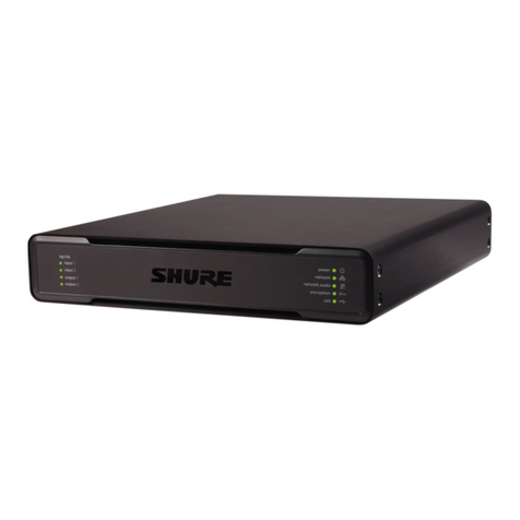
Shure INTELLIMIX P300 User manual

P300 AUDIO CONFERENCING PROCESSOR
USER GUIDE
© 2017 Shure Incorporated
27A27517 (Rev. 1)
Printed in U.S.A.
INTELLIMIX®
Le Guide de l’Utilisateur
Guia del Usuario
Guida dell’Utente
Руководство пользователя
Bedienungsanleitung
Gebruikershandleiding
Manual do Usuário


3
1. READ these instructions.
2. KEEP these instructions.
3. HEED all warnings.
4. FOLLOW all instructions.
5. DO NOT use this apparatus near water.
6. CLEAN ONLY with dry cloth.
7. DO NOT block any ventilation openings. Allow suffi-
cient distances for adequate ventilation and install in ac-
cordance with the manufacturer’s instructions.
8. DO NOT install near any heat sources such as open flames, radiators,
heat registers, stoves, or other apparatus (including amplifiers) that
produce heat. Do not place any open flame sources on the product.
9. DO NOT defeat the safety purpose of the polarized or ground-
ing type plug. A polarized plug has two blades with one wider
than the other. A grounding type plug has two blades and a third
grounding prong. The wider blade or the third prong are provided
for your safety. If the provided plug does not fit into your outlet,
consult an electrician for replacement of the obsolete outlet.
10. PROTECT the power cord from being walked on or
pinched, particularly at plugs, convenience receptacles,
and the point where they exit from the apparatus.
11. ONLY USE attachments/accessories specified by the manufacturer.
12. USE only with a cart, stand, tripod, bracket, or table spec-
ified by the manufacturer, or sold with the apparatus.
When a cart is used, use caution when moving the cart/
apparatus combination to avoid injury from tip-over.
13. UNPLUG this apparatus during lightning storms
or when unused for long periods of time.
14. REFER all servicing to qualified service personnel. Servicing is re-
quired when the apparatus has been damaged in any way, such as
power supply cord or plug is damaged, liquid has been spilled or ob-
jects have fallen into the apparatus, the apparatus has been exposed
to rain or moisture, does not operate normally, or has been dropped.
15. DO NOT expose the apparatus to dripping and splashing. DO NOT
put objects filled with liquids, such as vases, on the apparatus.
16. The MAINS plug or an appliance coupler shall remain readily operable.
17. The airborne noise of the Apparatus does not exceed 70dB (A).
18. Apparatus with CLASS I construction shall be connected to a
MAINS socket outlet with a protective earthing connection.
19. To reduce the risk of fire or electric shock, do not ex-
pose this apparatus to rain or moisture.
20. Do not attempt to modify this product. Doing so could re-
sult in personal injury and/or product failure.
21. Operate this product within its specified operating temperature range.
This symbol indicates that dangerous voltage constituting a risk
of electric shock is present within this unit.
This symbol indicates that there are important operating and
maintenance instructions in the literature accompanying this
unit.
IMPORTANT SAFETY INSTRUCTIONS
Note: Model information and power ratings are labeled on the
bottom of the unit.

4
Getting Started
This device features a browser-based web application, which controls
audio and network properties. Upon completing this basic setup process,
you will be able to:
• Access the web application to customize audio settings, signal routing,
and network properties
• Use Dante™ Controller software to connect with other Dante devices
and pass audio
• Access additional configuration information
Step 1: Connect to a Network
1. Use an Ethernet cable (CAT5e or higher) to con-
nect the P300 to a network switch.
Note: The network switch must provide Power over Ethernet Plus (PoE+). Make
sure to connect to a PoE+ port, since many switches do not supply power on all
ports.
2. Connect a computer to the network switch with an Ethernet cable
reset
input output usb
P300 Network Switch Computer
Step 2: Access the Web Application
1. Download and install the Shure Device Discovery
application (http://www.shure.com)
2. Open the Shure Device Discovery application
3. Double-click the device to open the web application.
Tip: If setting up multiple Shure devices, use the Identify button in the ap-
plication to flash the lights on the device.
Select the
device
Identify
Step 3: Connect Devices in Dante Controller
Software
1. Download and install Dante Controller Software
from http://www.audinate.com
2. Use Dante Controller to create connections with other Dante devices.
Important: For Shure devices with integrated automatic mixing (such
as the MXA910), connect independent channels to the P300 Dante in-
put channels to ensure effective acoustic echo cancellation.
Note: Refer to the Dante Controller user guide for more information
on channel routing (available at http://www.audinate.com/resources/
technical-documentation)
Example: Connecting the P300 and Shure MXA910
reset
input output usb
MXA910
P300
1. Find the MXA910 in the list of Dante transmitters, and se-
lect the plus sign (+) to show all channels.
2. Find the P300 in the list of Dante receivers, and se-
lect the plus sign (+) to show all channels.
3. Connect channels 1-8 from the MXA910 to Dante in-
put channels 1-8 on the P300. Do not use the auto-
mix output from the MXA910 into the P300.
Step 4: Configure Audio
The final configuration steps will vary, depending on the signal processing
required and hardware connected to the P300. These steps provide a
general guideline. Specific steps are included in the system examples.
1. Connect analog, USB, and mobile audio devices
2. Route signals in the matrix mixer
3. Adjust input and output levels in the input and output tabs
4. Turn on digital signal processing blocks as needed
5. Set the AEC reference channel by opening the AEC menu in the
schematic view or inputs tab and selecting a channel from the
pull-down menu. Use the channel that carries audio to loudspeak-
ers as the AEC reference. Analog -- To Speaker is the most
common channel for this application, in configurations using an
analog loudspeaker system or the built-in speaker on a display.
More comprehensive information is available in the help section of the
web application.
Access the help section

5
Get More Information
Now that the basic setup is complete, you should have access to the web
application and be able to pass audio between devices. More comprehen-
sive information is available online and in the help section, including:
• Maximizing audio quality with the built-in parametric equalizer
• External control system command strings
• Signal routing
• System scenario diagrams
• Software configuration
• Networking information
• Troubleshooting
• Replacement parts and accessories
The complete user guide is available at http://pubs.shure.com/guide/P300
USB Computer System
reset
input output usb
ULXD4
DigitalWirelessReceiver
push
control
ENTER
EXIT
SCAN
RF
A B
OL
OL
gain poweraudio
IR
on
ULXD2
Computer
Wireless Microphone
System MXA310
Powered
Loudspeaker
Network Switch
(PoE+ Required)
1. Connect the computer to the USB port on the P300
2. Connect a powered loudspeaker or amplifier to the P300 analog
output 2. In the matrix mixer, this is labeled Analog - To Speaker.
3. Connect additional analog sources (such as wire-
less microphones) to the P300 analog input 2.
4. In the P300 web application, open the matrix mix-
er to make connections between devices.
Note: Some connections are established in the matrix mixer by default. Refer to
the matrix mixer help topic in the web application for additional information.
Required Matrix Mixer Connections:
Input Output
Automix USB output
Analog input 2 USB output
USB input Analog - To Speaker
5. In the schematic view, right-click any AEC block and set
the AEC reference channel to Analog - To Speaker.
6. In the web application, adjust input and output lev-
els and perform a sound check. Refer to the help top-
ics in the web application for additional information.
Hardware Codec System
reset
input output usb
ULXD4
DigitalWirelessReceiver
push
control
ENTER
EXIT
SCAN
RF
A B
OL
OL
gain poweraudio
IR
on
ULXD2
Video Codec
Wireless Microphone System MXA910
Loudspeaker Network Switch
(PoE+ Required)
1. Connect the hardware codec audio output to the P300 analog in-
put 1. In the matrix mixer, this is labeled Analog - From Codec.
2. Connect the hardware codec audio input to the P300 analog out-
put 1. In the matrix mixer, this is labeled Analog - To Codec.
3. Connect a powered loudspeaker or amplifier to the P300 analog
output 2. In the matrix mixer, this is labeled Analog - To Speaker.
4. Connect additional analog sources (such as wire-
less microphones) to the P300 analog input 2.
5. In the P300 web application, open the matrix mix-
er to make connections between devices.
Note: Some connections are established in the matrix mixer by default. Refer to
the matrix mixer help topic in the web application for additional information.
Required Matrix Mixer Connections:
Input Output
Automix Analog - To codec
Analog input 2 Analog - To Codec
Analog - From Codec Analog - To Speaker
6. In the schematic view, right-click any AEC block and set
the AEC reference channel to Analog - To Speaker.
7. In the web application, adjust input and output lev-
els and perform a sound check. Refer to the help top-
ics in the web application for additional information.

6
Schematic View
The schematic view in the web application provides an overview of the en-
tire signal chain, with the ability to adjust settings and monitor signals.
Adjusting Settings
Right-click an input, output, or processing block to access the following
options:
Per Channel
Copy / paste
Copy and paste settings between items. For example, set the
equalizer curve on the USB output, and then use the same setting for
the analog output. Or, copy the gain and mute status from one input
channel to several others.
Mute / unmute
Mutes or activates the channel
Enable / disable
Turns processing on or off (does not apply to matrix mixer or
automixer)
Edit
Opens the dialog to adjust parameters
Global (right-click in blank area)
Mute all inputs
Mutes all input channels
Mute all outputs
Mutes all output channels
Unmute all inputs
Unmutes all input channels
Unmute all outputs
Unmutes all output channels
Close all dialogs
Clears all open dialogs from the workspace
Customizing the Workspace
Create a custom environment to monitor and control a set of inputs, out-
puts, and processing blocks from a single screen. There are two ways to
break out dialogs:
• Right click > edit
• Double-click the input, output, or processing block.
Open as many dialogs as you need to keep important controls available.
Metering and Signal Flow
A meter appears underneath each input and output to indicate signal lev-
els (dBFS).
The lines connecting inputs and outputs to the matrix mixer appear col-
ored when connections are established. When a signal is not routed, the
line appears gray. Use these tools to troubleshoot audio signals and verify
connections and levels.
Mobile Phone System
reset
input output usb
Phone
MXA310
Loudspeaker
Network Switch
(PoE+ Required)
In this example, when the phone is plugged in, the built-in microphone and
speaker are disabled -- the phone simply carries the call. The MXA310
microphone captures near-end audio, and the loudspeaker delivers audio
from the far end of the call.
1. Connect the phone to the P300 with a 1/8-inch TRRS cable
2. Connect a powered loudspeaker or amplifier to the P300 analog
output 2. In the matrix mixer, this is labeled Analog - To Speaker.
3. In the P300 web application, open the matrix mix-
er to make connections between devices.
Note: Some connections are established in the matrix mixer by default. Refer to
the matrix mixer help topic in the web application for additional information.
Required Matrix Mixer Connections:
Input Output
Automix Mobile output
Mobile input Analog - To Speaker
4. In the schematic view, right-click any AEC block and set
the AEC reference channel to Analog - To Speaker.
5. In the web application, adjust input and output lev-
els and perform a sound check. Refer to the help top-
ics in the web application for additional information.
Mobile Connection Cable Requirements
A 1/8-inch TRRS cable is required to connect a phone to the P300. Avoid
using cables with a metal flange, as it may create an electrical connection
to the exterior of the phone and interrupt the signal.
To ensure proper operation, only use:
• Apple-approved cables
• Cables with a plastic or non-conductive flange
Tip Ring Ring Sleeve
Flange (non-conductive)
Note: If necessary, a TRS (tip/ring/sleeve) cable may be used to plug a
stereo device into the P300, but the device will only be able to send audio
to the P300. The Enable auto-mute feature (located in the mobile channel
of the input section in the web application) must be turned off in this case.
Metal flange

7
reset
input output usb
௦
Rear Panel
sig/clip power
network
network audio
encryption
input 1
input 2
output 1
output 2 usb
௦
Front panel
① Mobile Input
TRRS mobile input connects to a mobile device. Supports bidirectional
audio with a TRRS cable. Sends audio in to the P300 with a TRS
cable.
Note: See the cable requirements topic for additional information
Pin Assignments:
Tip Audio Input (Left)
Ring 1 Audio Input (Right )
Ring 2 Ground
Sleeve Audio Output (To Phone)
Note: Left and Right audio signals are summed to a mono signal.
② Audio Inputs (Block Connector)
Balanced audio input connects to an analog audio device. Set the
analog input level in the web application to match the output level of
the analog device.
Input sensitivity:
Line (+4 dBu)
Aux (-10 dBV)
Block Pin Assignments:
Audio +
Audio -
Audio ground
③ Chassis Ground Screw
Provides an optional connection for microphone shield wire to chassis
ground.
④ Audio Outputs (Block Connector)
Balanced audio output connects to an analog device. Set the output
level in the web application to match the input sensitivity of the analog
device (Line, Aux, or Mic level).
Audio +
Audio -
Audio ground
⑤ USB Port
Connects to a computer to send and receive up to 2 input or output
audio channels.
⑥ Dante Network Port
Connects to a network switch to connect Dante™ audio, Power over
Ethernet (PoE), and data from the control software.
⑦ Reset Button
Resets the device settings back to the factory default
⑧ LED Indicators
Power
Network
Network Audio
Encryption
USB
Power: Power over Ethernet Plus (PoE+) present
Note: Use a PoE+ injector if your network switch does not supply PoE+.
Network: Ethernet connection active
Network Audio: Dante™ audio present on the network
Note: Error details are available in the event log in the web application.
Network Audio LED Behavior
LED Status Activity
Off No active signal
Green Device is operating successfully
Red Error has occurred. See event log for details.
Encryption:
LED Status Activity
Off Audio not encrypted
Green Encryption enabled
Red Encryption error. Possible causes:
• Encryption is enabled on one device and not on another
• Passphrase mismatch
USB Audio
LED State Status
Off No USB device connected
Green USB device operating successfully
Red (flashing) Problem detected with connected USB audio device
⑨ Level Indicators (Signal/Clip)
Tri-color LEDs indicate the audio signal level for the analog channels
and connectivity status for the USB channel. Adjust output levels in the
web application to avoid clipping.
Analog Input/Output
LED State Audio Signal Level
Off less than -60 dBFS
Green -60 dBFS to -18 dBFS
Yellow -18 dBFS to -6 dBFS
Red -6 dBFS or more
Note: The input and output LEDs stay off when metering is set to Post Fader and
the channel is muted in the web application.
P300 Hardware

8
Installation and Rack Mounting
Two mounting solutions are available for installing the P300:
CRT1 19" Rack Tray (optional accessory): Supports up to 2 devices
(two P300s or one P300 and one ANI4IN, ANI4OUT, ANI22, or ANIUSB);
mountable in a rack or under a table
Single-unit Mounting Tray (included accessory): Supports a single de-
vice for mounting under a table
Securing the Devices
Use the included screws from the mounting hardware kit to secure each
P300 or Audio Network Interface (ANI). Devices can be mounted to face
either direction. Insert the screws from the bottom in the appropriate holes,
according to the following diagrams:
Installing Underneath a Table
1. Hold the tray in the desired location under a table
2. Use a pencil to mark the location of the mounting holes on the table.
3. Drill 4 holes for the screws. The diame-
ter of the holes in the tray are 7.1 mm.
4. Install the components into the tray
5. Install with 4 screws to secure the tray underneath the table
Power Over Ethernet Plus (PoE+)
This device requires PoE Plus to operate. It is compatible with both Class
4PoE+ sources.
Power over Ethernet is delivered in one of the following ways:
• A network switch that provides PoE+
• A PoE+ injector device (must be a Gigabit device)
Reset
The reset button is located inside a small hole in the rear panel. Use a pa-
perclip or other small tool to press the button.
There are two hardware reset functions:
Network reset (press button for 4-8 seconds)
Resets all Shure control and audio network IP settings to factory
defaults
Full factory reset (press button for longer than 8 seconds)
Restores all network and web application settings to the factory
defaults.
Software Reset Options
Reboot Device:In the web application (settings > factory reset), there is a
Reboot Device button, which simply power-cycles the device as if it were
unplugged from the network. All settings are retained when the device is
rebooted.
Restore Factory Defaults: In the web application (settings > factory re-
set), this restores all network and web application settings to the factory
defaults. This is the same as performing a full factory reset using the reset
button on the device.
Default Settings Preset: To revert audio settings back to the factory con-
figuration (excluding Device Name, IP Settings, and Passwords), select
Load Preset and choose the default settings preset.
Networking and Dante
Digital Audio Networking
Dantetm digital audio is carried over standard Ethernet and operates using
standard Internet Protocols. Dante provides low latency, tight clock syn-
chronization, and high Quality-of-Service (QoS) to provide reliable audio
transport to a variety of Dante devices. Dante audio can coexist safely on
the same network as IT and control data, or can be configured to use a
dedicated network.
Switch Recommendations for Dante
Networking
In addition to the basic networking requirements, Dante audio networks
should use a Gigabit network switch or router with the following features:
• Gigabit ports
• Quality of Service (QoS) with 4 queues
• Diffserv (DSCP) QoS, with strict priority
• Recommended: A managed switch to provide detailed information
about the operation of each network link (port speed, error counters,
bandwidth used)
Standard 19" Rack Mount
1. Align the ears with
the mounting holes
pointed forward.
2. Install the two screws
that hold the ear to
the tray as shown.
Under-table Mounting
1. Align the ears with
the mounting holes
pointed upward.
2. Install the two screws
that hold the ear to
the tray as shown.
Align the holes as shown for securing a single device in the single-unit
mounting tray
P300 1 P300 2
Align the holes as shown for securing up to two devices in the 19" rack
tray.
P300
ANI
Rack Ear Configuration (CRT1)
The adjustable rack ears support mounting in a standard equipment rack
or underneath a table.

9
Cable Requirements
Always use Cat5E cable or higher.
QoS (Quality of Service) Settings
QoS settings assign priorities to specific data packets on the network, ensuring reliable audio delivery on larger networks with heavy traffic. This feature
is available on most managed network switches. Although not required, assigning QoS settings is recommended.
Note: Coordinate changes with the network administrator to avoid disrupting service.
To assign QoS values, open the switch interface and use the following table to assign Dante™-associated queue values.
• Assign the highest possible value (shown as 4 in this example) for time-critical PTP events
• Use descending priority values for each remaining packet.
Dante QoS Priority Values
Priority Usage DSCP Label Hex Decimal Binary
High (4) Time-critical PTP events CS7 0x38 56 111000
Medium (3) Audio, PTP EF 0x2E 46 101110
Low (2) (reserved) CS1 0x08 8 001000
None (1) Other traffic BestEffort 0x00 0 000000
Note: Switch management may vary by manufacturer and switch type. Consult the manufacturer's product guide for specific configuration details.
For more information on Dante requirements and networking, visit www.audinate.com.
Networking Terminology
PTP (Precision Time Protocol): Used to synchronize clocks on the network
DSCP (Differentiated Services Code Point): Standardized identification method for data used in layer 3 QoS prioritization
Networking
Networking Best Practices
Use the following best practices when setting up a network to ensure reli-
able communication:
• Always use a "star" network topology by connecting each component
directly to the switch or router.
• Connect all Shure networked devices to the same network and set to
the same subnet. This applies to all devices that audio signals must be
routed between (managed through Dante Controller). It is also required
in order to open the web application for a device.
• Devices on separate networks require an audio processor or conferenc-
ing software to carry audio between them. See the system planning and
gear requirements section for network setup information and configura-
tion examples.
• Use only 1 DHCP server per network. Disable DHCP addressing on
additional servers.
• Power on the switch and DHCP server prior to MXA equipment.
• To expand the network, use multiple Ethernet switches in a star
topology.
• All devices must be at the same firmware revision level.
Network Audio and Shure Control Data
Microflex®Advance™ devices transport two types of data over the net-
work: Shure Control and Network Audio.
Shure Control
The Shure Control carries data for the control software operation,
firmware updates and 3rd party control systems (AMX, Crestron).
Network Audio
This network carries both the Dante digital audio and the control data
for Dante Controller. The network audio requires a wired, gigabit
Ethernet connection to operate.
Device IP Settings
Configure IP
Sets IP mode of the selected network interface:
- Auto (DHCP): For automatic assignment of IP addresses.
- Manual (Static): For Static IP addresses.
IP Settings
View and edit the IP Address, Subnet Mask, and Gateway for each
network interface.
MAC Address
The network interface's unique identification.
Configuring IP Settings
IP configurations are managed through the web application. By default,
they are set to Automatic (DHCP) mode. DHCP mode enables the devices
to accept IP settings from a DHCP server, or automatically fall back to
Link-Local settings when no DHCP is available. IP addresses may also be
manually set.
To configure the IP properties, follow these steps:
1. Open the web application.
2. Go to the Settings tab and select Network.
3. Select Auto or Manual. If Auto is used, addresses
will be automatically assigned. For Manual setup, fol-
low the instructions on manual configuration.
Manually Assigning Static IP Address
To manually assign IP addresses, follow these steps:
1. Open the web application.
2. Go to the Settings tab and select Network.
3. Select Manual as the Configure IP setting.
4. Enter the IP settings.
10
Setting Latency
Latency is the amount of time for a signal to travel across the system to
the outputs of a device. To account for variances in latency time between
devices and channels, Dante has a predetermined selection of latency set-
tings. When the same setting is selected, it ensures that all Dante devices
on the network are in sync.
The latency setting for Dante devices should be set according to the num-
ber of switches in the network.
Use Audinate's Dante Controller software to change the latency setting.
Latency Recommendations
Latency Setting Maximum Number of Switches
0.25 ms 3
0.5 ms (default) 5
1 ms 10
2 ms 10+
Operating the Control Software over Wi-Fi
When operating the web application over Wi-Fi, it’s important to set up
the wireless router properly for best performance. The system employs
several standard-based protocols that rely on multicast. Wi-Fi treats
broadcast and multicast packets differently than general packets for
backward compatibility reasons. In some cases, the Wi-Fi router will limit
the multicast packet transmission rate to a value that is too slow for web
application to properly operate.
Wi-Fi routers typically support 802.11b, 802.11a/g, and/or 802.11n
standards. By default, many Wi-Fi routers are configured to allow older
802.11b devices to operate over the network. In this configuration, these
routers will automatically limit the multicast data rates (or sometimes re-
ferred to as ‘basic rate’, or ‘management rate’) to 1-2Mbps.
Note: A Wi-Fi connection can only be used for the control software.
Network audio cannot be transmitted over Wi-Fi.
Tip: For larger wireless microphone configurations, it’s recommended to
increase the multicast transmission rate to provide adequate bandwidth.
Important: For best performance, use a Wi-Fi router that does not limit
the multicast rate to 1-2 Mbps.
Shure recommends the following Wi-Fi router brands:
• Cisco
• Linksys
• Apple
IP Ports and Protocols
Shure Control
Port TCP/UDP Protocol Description Factory Default
21 tcp FTP Required for firmware updates (otherwise closed) Closed
22 tcp SSH Secure shell interface Closed
23 tcp Telnet Not supported Closed
68 udp DHCP Dynamic Host Configuration Protocol Open
80* tcp HTTP Required to launch embedded web server Open
443 tcp HTTPS Not supported Closed
161 tcp SNMP Not supported Closed
162 tcp SNMP Not supported Closed
2202 tcp ASCII Required for 3rd party control strings Open
5353 udp mDNS†Required for device discovery Open
5568 udp SDT†Required for inter-device communication Open
8023 tcp Telnet Debug console interface Password
8180* tcp HTML Required for web application Open
8427 udp Multcast SLP†Required for inter-device communication Open
64000 tcp Telnet Required for Shure firmware update Open

11
Analog Connections
Input (2) 3-pin block connector (Active Balanced)
Output (2) 3-pin block connector (Impedance Balanced)
Mobile (1) TRRS 3.5 mm (1/8")
USB Connections
(1) USB 2.0, Type B
Single port carries 2 input and 2 output channels (Summed mono)
Network Connections (Dante Digital Audio)
(1) RJ45
10 Dante input channels, 2 output channels
Polarity
Non-inverting, any input to any output
Power Requirements
802.3 at Type 2 (PoE Plus), Class 4
Power Consumption
17.5 W, maximum
Weight
1710 g (3.8 lbs)
Dimensions
H x W x D
4 x 21 x 22.6 cm (1.6 x 8.3 x 8.9 in.)
control application
HTML5 Browser-based
Operating Temperature Range
−6.7°C (20°F) to 50°C (122°F)
Storage Temperature Range
−29°C (-20°F) to 74°C (165°F)
Thermal Power Dissipation
Maximum 17.5 W (60 BTU/hr)
typical 14.6 W (50 BTU/hr)
Audio
Frequency Response
+1, -1.5 dB
20 to 20,000 Hz
Dante Digital Audio
Sampling Rate 48 kHz
Bit Depth 24
Dante Audio & Controller
Port TCP/UDP Protocol Description
162 udp SNMP Used by Dante
[319-320]* udp PTP†Dante clocking
2203 udp Custom Required for packet bridge
4321, 14336-14600 udp Dante Dante audio
[4440, 4444, 4455]* udp Dante Dante audio routing
5353 udp mDNS†Used by Dante
[8700-8706, 8800]* udp Dante Dante Control and Monitoring
8751 udp Dante Dante Controller
16000-65536 udp Dante Used by Dante
*These ports must be open on the PC or control system to access the device through a firewall.
†These protocols require multicast. Ensure multicast has been correctly configured for your network.
USB Audio
Sampling Rate 44.1, 48 kHz
Bit Depth 16, 24
Latency
Does not include Dante latency Dante 1-8 in to Dante out (AEC enabled) 12.5 ms
Dante 1-8 in to Dante out (AEC disabled) 5.8 ms
Dante 9-10 in to Dante out 1.8 ms
Analog in to Analog out 2.2 ms
Analog Connections (Block Connectors)
Dynamic Range
20 Hz to 20 kHz, A-weighted, typical
Analog-to-Dante 113 dB
Dante-to-Analog 117 dB
Equivalent Input Noise
20 Hz to 20 kHz, A-weighted, input terminated with 150Ω
Line -86 dBV
Aux -98 dBV
Total Harmonic Distortion
@ 1 kHz, 0 dBV Input, 0 dB analog gain
<0.05%
Common Mode Rejection Ratio
150Ω balanced source @ 1 kHz
>50 dB
Input Impedance
9.6 kΩ
Input Clipping Level
Line +27 dBV
Aux +15 dBV
Output Impedance
80 Ω
Output Clipping Level
Line +20 dBV
Aux +0 dBV
Mic -26 dBV
Specifications

12
Mobile Connection (3.5 mm Connector)
Pin Assignments
Tip Audio Input (Left)
Ring 1 Audio Input (Right )
Ring 2 Ground
Sleeve Audio Output (To Phone)
Dynamic Range
20 Hz to 20 kHz, A-weighted, typical
Analog-to-Dante 99 dB
Dante-to-Analog 90 dB
Equivalent Input Noise
20 Hz to 20 kHz, A-weighted, input terminated with 20Ω
-95 dBV
Total Harmonic Distortion
@ 1 kHz, 0 dBV Input, 0 dB analog gain
<0.05%
Input Impedance
3.7 kΩ
Input Clipping Level
+4 dBV
Output Impedance
1.4 kΩ
Output Clipping Level
Output terminated with 2.2 kΩ
-20 dBV
Networking
Cable Requirements
Cat 5e or higher (shielded cable recommended)
Important Product Information
The equipment is intended to be used in professional audio applications.
Note: This device is not intended to be connected directly to a public inter-
net network.
EMC conformance to Environment E2: Commercial and Light Industrial.
Testing is based on the use of supplied and recommended cable types.
The use of other than shielded (screened) cable types may degrade EMC
performance.
Changes or modifications not expressly approved by Shure Incorporated
could void your authority to operate this equipment.
Industry Canada ICES-003 Compliance Label: CAN ICES-3 (B)/
NMB-3(B)
Authorized under the verification provision of FCC Part 15B.
Please follow your regional recycling scheme for batteries, packaging, and
electronic waste.
Information to the user
This equipment has been tested and found to comply with the limits for a
Class B digital device, pursuant to Part 15 of the FCC Rules. These limits
are designed to provide reasonable protection against harmful interference
in a residential installation. This equipment generates uses and can radi-
ate radio frequency energy and, if not installed and used in accordance
with the instructions, may cause harmful interference to radio communi-
cations. However, there is no guarantee that interference will not occur in
a particular installation. If this equipment does cause harmful interference
to radio or television reception, which can be determined by turning the
equipment off and on, the user is encouraged to try to correct the interfer-
ence by one or more of the following measures:
• Reorient or relocate the receiving antenna.
• Increase the separation between the equipment and the receiver.
• Connect the equipment to an outlet on a circuit different from that to
which the receiver is connected.
• Consult the dealer or an experienced radio/TV technician for help.
The CE Declaration of Conformity can be obtained from: www.shure.com/
europe/compliance
Authorized European representative:
Shure Europe GmbH
Headquarters Europe, Middle East & Africa
Department: EMEA Approval
Jakob-Dieffenbacher-Str. 12
75031 Eppingen, Germany
Phone: +49-7262-92 49 0
Fax: +49-7262-92 49 11 4
Email: [email protected]
This product meets the Essential Requirements of all relevant European
directives and is eligible for CE marking.
The CE Declaration of Conformity can be obtained from Shure
Incorporated or any of its European representatives. For contact informa-
tion please visit www.shure.com
Accessories
Furnished Accessories
KIT, HARDWARE, P300-IMX 90D33522
BRACKET, HALF RACK UNIT 53A27741
Optional Accessories and Replacement Parts
19" rack tray CRT1

13
1. LIRE ces consignes.
2. CONSERVER ces consignes.
3. OBSERVER tous les avertissements.
4. SUIVRE toutes les consignes.
5. NE PAS utiliser cet appareil à proximité de l’eau.
6. NETTOYER UNIQUEMENT avec un chiffon sec.
7. NE PAS obstruer les ouvertures de ventilation. Laisser des dis-
tances suffisantes pour permettre une ventilation adéquate et ef-
fectuer l’installation en respectant les instructions du fabricant.
8. NE PAS installer à proximité d’une source de chaleur telle qu’une
flamme nue, un radiateur, une bouche de chaleur, un poêle ou
d’autres appareils (dont les amplificateurs) produisant de la chal-
eur. Ne placer aucune source à flamme nue sur le produit.
9. NE PAS retirer le dispositif de sécurité de la fiche polarisée ou de la fiche
de terre. Une fiche polarisée comporte deux lames dont l’une est plus
large que l’autre. Une fiche de terre comporte deux lames et une troisième
broche de mise à la terre. La lame la plus large ou la troisième broche as-
sure la sécurité de l’utilisateur. Si la fiche fournie ne s’adapte pas à la prise
électrique, demander à un électricien de remplacer la prise hors normes.
10. PROTÉGER le cordon d’alimentation afin que personne ne marche
dessus et que rien ne le pince, en particulier au niveau des fich-
es, des prises de courant et du point de sortie de l’appareil.
11. UTILISER UNIQUEMENT les accessoires spécifiés par le fabricant.
12. UTILISER uniquement avec un chariot, un pied, un trépied, un support
ou une table spécifié par le fabricant ou vendu avec l’appareil. Si un
chariot est utilisé, déplacer l’ensemble chariot-appareil avec précaution
afin de ne pas le renverser, ce qui pourrait entraîner des blessures.
13. DÉBRANCHER l’appareil pendant les orages ou quand
il ne sera pas utilisé pendant longtemps.
14. CONFIER toute réparation à du personnel qualifié. Des répara-
tions sont nécessaires si l’appareil est endommagé d’une façon
quelconque, par exemple : cordon ou prise d’alimentation en-
dommagé, liquide renversé ou objet tombé à l’intérieur de l’ap-
pareil, exposition de l’appareil à la pluie ou à l’humidité, appareil
qui ne marche pas normalement ou que l’on a fait tomber.
15. NE PAS exposer cet appareil aux égouttures et aux éclaboussements. NE
PAS poser des objets contenant de l’eau, comme des vases, sur l’appareil.
16. La prise SECTEUR ou un coupleur d’appareil élec-
trique doit rester facilement utilisable.
17. Le bruit aérien de l’appareil ne dépasse pas 70 dB (A).
18. L’appareil de construction de CLASSE I doit être raccordé à une
prise SECTEUR dotée d’une protection par mise à la terre.
19. Pour réduire les risques d’incendie ou de choc électrique,
ne pas exposer cet appareil à la pluie ou à l’humidité.
20. Ne pas essayer de modifier ce produit. Une telle opération est sus-
ceptible d’entraîner des blessures ou la défaillance du produit.
21. Utiliser ce produit dans sa plage de tempéra-
tures de fonctionnement spécifiée.
Ce symbole indique la présence d’une tension dangereuse
dans l’appareil constituant un risque de choc électrique.
Ce symbole indique que la documentation fournie avec l’ap-
pareil contient des instructions d’utilisation et d’entretien
importantes.
CONSIGNES DE SÉCURITÉ IMPORTANTES

14
Premiers pas
Cet appareil est accompagné d’une application basée sur navigateur Web
qui contrôle les propriétés audio et de réseau. À la fin de cette procédure
de configuration générale, l’utilisateur pourra :
• Accéder à l’application Web pour personnaliser les réglages audio,
l’acheminement du signal et les propriétés du réseau
• Utiliser le logiciel Dante™ Controller pour connecter l’appareil à d’au-
tres appareils Dante et transférer le son
• Accéder aux informations complémentaires relatives à la configuration
Étape 1 : Connexion à un réseau
1. Utiliser un câble Ethernet (Cat5e ou supérieure) pour
connecter le P300 à un commutateur réseau.
Remarque : le commutateur réseau doit fournir une alimentation via Ethernet
Plus (PoE+). Veiller à utiliser un port PoE+ dans la mesure où de nombreux com-
mutateurs ne fournissent pas d’alimentation sur tous les ports.
2. Raccorder un ordinateur au un commuta-
teur réseau avec un câble Ethernet
reset
input output usb
P300 Commutateur réseau Ordinateur
Étape 2 : Accès à l’application Web
1. Télécharger et installer application Shure Device
Discovery (http://www.shure.com).
2. Ouvrir l’application Shure Device Discovery
3. Double-cliquer sur l’appareil pour ouvrir l’application Web.
Conseil : lors de la configuration de plusieurs appareils Shure, appuyer
sur le bouton Identifier de l’application pour faire clignoter les témoins de
l’appareil.
Sélectionner
l’appareil
Identifier
Étape 3 : Connexion d’appareils au logiciel
Dante Controller
1. Télécharger et installer le logiciel Dante Controller
depuis http://www.audinate.com
2. Utiliser Dante Controller pour créer des connex-
ions avec d’autres appareils Dante.
Important : pour les appareils Shure avec mixage automatique intégré
(comme MXA910), connecter les canaux indépendants au canaux d’en-
trée Dante P300 pour éliminer de manière efficace l’écho acoustique.
Remarque : se reporter au Guide d’utilisation de Dante Controller pour
plus d’informations sur l’acheminement des canaux (disponible sur http://
www.audinate.com/resources/technical-documentation)
Exemple : Connexion du P300 et du MXA910 de Shure
reset
input output usb
MXA910
P300
1. Rechercher le MXA910 dans la liste des émetteurs Dante et
sélectionner le signe plus (+) pour afficher tous les canaux.
2. Rechercher le P300 dans la liste des récepteurs Dante et sélec-
tionner le signe plus (+) pour afficher tous les canaux.
3. Connecter les canaux 1 à 8 de l’émetteur MXA910 aux canaux
d’entrées Dante 1 à 8 du récepteur P300. Ne pas utiliser la sor-
tie de mélange automatique du MXA910 vers le P300.
Étape 4 : Configuration audio
Les dernières étapes de configuration varient selon le traitement des sig-
naux requis et le matériel raccordé au P300. Elles sont fournies à titre in-
dicatif. D’autres étapes plus spécifiques sont détaillées dans les exemples
de système.
1. Connexion d’appareils analogiques, USB et mobiles audio
2. Acheminement des signaux dans le mélangeur matriciel
3. Ajustement des niveaux d’entrée et de sor-
tie dans les onglets correspondants
4. Activation des blocs de traitement des sig-
naux numériques, le cas échéant
5. Pour régler le canal de référence AEC, ouvrir le menu AEC dans
le schéma de l’application ou dans l’onglet des entrées puis sélec-
tionner un canal dans le menu déroulant. Utiliser le canal qui con-
duit le son vers les haut-parleurs comme référence AEC.Analog
-- To Speaker n’est pas le canal le plus courant pour cette
application, dans des configurations utilisant un système de haut-
parleurs analogiques ou l’enceinte intégrée sur un écran.
De plus amples informations sont disponibles dans la section d’aide de
l’application Web.
Access the help section

15
Obtenir plus d’informations
Maintenant que la configuration générale est terminée, l’application Web
est accessible et il est possible de transférer le son entre les différents
appareils. De plus amples informations sont disponibles en ligne et dans
la section d’aide, notamment :
• Optimisation de la qualité audio avec l’égaliseur paramétrique intégré
• Chaînes de commande du système de contrôle externe
• Acheminement du signal
• Schémas de disposition de systèmes
• Configuration du logiciel
• Informations de mise en réseau
• Dépannage
• Pièces de rechange et accessoires
Le guide d’utilisation complet est disponible sur http://pubs.shure.com/
guide/P300
Système informatique USB
reset
input output usb
ULXD4
DigitalWirelessReceiver
push
control
ENTER
EXIT
SCAN
RF
A B
OL
OL
gain poweraudio
IR
on
ULXD2
Ordinateur
Système de microphone
sans fil MXA310
Haut-parleur
alimenté
Commutateur
réseau
(PoE+ requis)
1. Raccorder l’ordinateur au port USB du P300
2. Raccorder un haut-parleur alimenté ou un amplificateur
à la sortie analogique 2 du P300. Sur le mélangeur ma-
triciel, elle est étiquetée Analog - To Speaker.
3. Raccorder les sources analogiques supplémentaires (comme
des microphones sans fil) à l’entrée analogique 2 du P300.
4. Dans l’application Web du P300, ouvrir le mélangeur matric-
iel pour effectuer des connexions entre les appareils.
Remarque : certaines connexions sont établies par défaut dans le mélangeur ma-
triciel. Se reporter aux sujets d’aide de l’application Web consacrés au mélangeur
matriciel pour plus d’informations.
Connexions requises du mélangeur matriciel :
Entrée Sortie
Mélange automatique Sortie USB
Entrée analogique 2 Sortie USB
Entrée USB Analogique — Vers Haut-parleur
5. Dans le schéma de l’application, effectuer un clic-
droit sur un bloc AEC, quel qu’il soit, et régler le ca-
nal de référence AEC sur Analog - To Speaker.
6. Dans l’application Web, ajuster les niveaux d’entrée et de
sortie et vérifier le son. Se reporter aux sujets d’aide de l’ap-
plication Web pour de plus amples informations.
Système de codec matériel
reset
input output usb
ULXD4
DigitalWirelessReceiver
push
control
ENTER
EXIT
SCAN
RF
A B
OL
OL
gain poweraudio
IR
on
ULXD2
Video Codec
Wireless Microphone System MXA910
Loudspeaker Network Switch
(PoE+ Required)
1. Raccorder la sortie codec audio matérielle à l’en-
trée analogique 1 du P300. Sur le mélangeur matric-
iel, elle est étiquetée Analog - From Codec.
2. Raccorder l’entrée codec audio matérielle à la sortie analogique 1 du
P300. Sur le mélangeur matriciel, elle est étiquetée Analog - To Codec.
3. Raccorder un haut-parleur alimenté ou un amplificateur
à la sortie analogique 2 du P300. Sur le mélangeur ma-
triciel, elle est étiquetée Analog - To Speaker.
4. Raccorder les sources analogiques supplémentaires (comme
des microphones sans fil) à l’entrée analogique 2 du P300.
5. Dans l’application Web du P300, ouvrir le mélangeur matric-
iel pour effectuer des connexions entre les appareils.
Remarque : certaines connexions sont établies par défaut dans le mélangeur ma-
triciel. Se reporter aux sujets d’aide de l’application Web consacrés au mélangeur
matriciel pour plus d’informations.
Connexions requises du mélangeur matriciel :
Entrée Sortie
Mélange automatique Analogique — Vers codec
Entrée analogique 2 Analogique — Vers Codec
Analogique — Depuis Codec Analogique — Vers Haut-parleur
6. Dans le schéma de l’application, effectuer un clic-
droit sur un bloc AEC, quel qu’il soit, et régler le ca-
nal de référence AEC sur Analog - To Speaker.
7. Dans l’application Web, ajuster les niveaux d’entrée et de
sortie et vérifier le son. Se reporter aux sujets d’aide de l’ap-
plication Web pour de plus amples informations.

16
Schéma
Le schéma de l’application Web offre un aperçu de l’ensemble de la
chaîne de signal tout en permettant de régler les paramètres et de sur-
veiller les signaux.
Réglage des paramètres
Faire un clic droit sur une entrée, une sortie ou un bloc de traitement pour
accéder aux options suivantes :
Par canal
Copier/coller
Copier et coller les paramètres d’un élément à l’autre. Par exemple,
régler la courbe de l’égaliseur sur la sortie USB puis utiliser le même
réglage pour la sortie analogique. Il est également possible de copier
le gain et l’état de coupure d’un canal d’entrée vers plusieurs autres.
Couper/rétablir le son
Couper le son ou active un canal
Activer/désactiver
Active ou désactive le traitement (non applicable au mélangeur
matriciel ou mélangeur automatique)
Modifier
Ouvre la boîte de dialogue afin de régler les paramètres
Mondial (faire un clic droit dans la zone vierge)
Coupure de toutes les entrées
Coupe tous les canaux d’entrée
Coupure de toutes les sorties
Coupe tous les canaux de sortie
Rétablir le son de toutes les entrées
Rétablit le son de tous les canaux d’entrée
Rétablir le son de toutes les sorties
Rétablit le son de tous les canaux de sortie
Fermer toutes les boîtes de dialogue
Ferme toutes les boîtes de dialogue ouvertes dans la zone de travail
Personnalisation de la zone de travail
Créer un environnement personnalisé pour surveiller et contrôler un en-
semble d’entrées, de sorties et de blocs de traitement depuis un écran
unique. Les boîtes de dialogue peuvent être fermées de deux façons :
• Clic droit > modifier
• Double-cliquer sur l’entrée, la sortie ou le bloc de traitement.
Ouvrir autant de boîtes de dialogue que nécessaire pour que les com-
mandes importantes restent disponibles.
Mesure et flux des signaux
Un compteur s’affiche sous chaque entrée et sortie ; il indique le niveau
des signaux (dBFS).
Les lignes reliant les entrées et les sorties au mélangeur matriciel sont en
couleur lorsque les connexions sont établies. Lorsqu’un signal n’est pas
acheminé, la ligne s’affiche en gris. Utiliser ces outils pour diagnostiquer
les signaux audio et vérifier les connexions et les niveaux.
Système de téléphone portable
reset
input output usb
Phone
MXA310
Loudspeaker
Network Switch
(PoE+ Required)
Dans cet exemple, quand le téléphone est branché, le microphone et
le haut-parleur intégrés sont désactivés : le téléphone se contente de
transmettre l’appel. Le microphone MXA310 capture le son de l’extrémité
proche et le haut-parleur transmet le son de l’extrémité distante de l’appel.
1. Raccorder le téléphone au P300 à l’aide d’un câble TRRS 1/8 pouce
2. Raccorder un haut-parleur alimenté ou un amplificateur
à la sortie analogique 2 du P300. Sur le mélangeur ma-
triciel, elle est étiquetée Analog - To Speaker.
3. Dans l’application Web du P300, ouvrir le mélangeur matric-
iel pour effectuer des connexions entre les appareils.
Remarque : certaines connexions sont établies par défaut dans le mélangeur ma-
triciel. Se reporter aux sujets d’aide de l’application Web consacrés au mélangeur
matriciel pour plus d’informations.
Connexions requises du mélangeur matriciel :
Entrée Sortie
Mélange automatique Sortie du portable
Entrée du portable Analogique — Vers Haut-parleur
4. Dans le schéma de l’application, effectuer un clic-
droit sur un bloc AEC, quel qu’il soit, et régler le ca-
nal de référence AEC sur Analog - To Speaker.
5. Dans l’application Web, ajuster les niveaux d’entrée et de
sortie et vérifier le son. Se reporter aux sujets d’aide de l’ap-
plication Web pour de plus amples informations.
Pointe Anneau Anneau
Corps
Bride (non conductrice)
Remarque : au besoin, un câble à connecteur TRS (Tip/Ring/Sleeve, ou
pointe/anneau/corps) peut être utilisé pour raccorder un appareil stéréo au
P300, mais seul le son pourra être envoyé au P300. La fonction Enable
auto-mute (qui se trouve dans le canal Mobile de la section Entrée de l’ap-
plication Web) doit alors être désactivée.
Bride métallique
Spécifications du câble de connexion
pour portable
Pour raccorder un téléphone au P300, utiliser un câble TRRS 1/8 pouce.
Éviter tout câble avec bride métallique qui conduit l’électricité vers l’ex-
térieur du téléphone et interrompt le signal.
Pour un fonctionnement optimal, utiliser uniquement :
• Câbles agréés Apple
• Câbles avec bride plastique non conductrice

17
reset
input output usb
௦
Rear Panel
sig/clip power
network
network audio
encryption
input 1
input 2
output 1
output 2 usb
௦
Front panel
① Mobile Input
TRRS mobile input connects to a mobile device. Supports bidirectional
audio with a TRRS cable. Sends audio in to the P300 with a TRS
cable.
Note: See the cable requirements topic for additional information
Pin Assignments:
Pointe Entrée audio (Gauche)
Anneau 1 Entrée audio (Droite )
Anneau 2 Masse
Corps Sortie audio (To Phone)
Note: Left and Right audio signals are summed to a mono signal.
② Audio Inputs (Block Connector)
Balanced audio input connects to an analog audio device. Set the
analog input level in the web application to match the output level of
the analog device.
Input sensitivity:
Line (+4 dBu)
Aux (-10 dBV)
Block Pin Assignments:
Audio +
Audio -
Audio ground
③ Chassis Ground Screw
Provides an optional connection for microphone shield wire to chassis
ground.
④ Audio Outputs (Block Connector)
Balanced audio output connects to an analog device. Set the output
level in the web application to match the input sensitivity of the analog
device (Line, Aux, or Mic level).
Audio +
Audio -
Audio ground
⑤ USB Port
Connects to a computer to send and receive up to 2 input or output
audio channels.
⑥ Dante Network Port
Connects to a network switch to connect Dante™ audio, Power over
Ethernet (PoE), and data from the control software.
⑦ Reset Button
Resets the device settings back to the factory default
⑧ LED Indicators
Power
Network
Network Audio
Encryption
USB
Power: Power over Ethernet Plus (PoE+) present
Note: Use a PoE+ injector if your network switch does not supply PoE+.
Network: Ethernet connection active
Network Audio: Dante™ audio present on the network
Note: Error details are available in the event log in the web application.
Network Audio LED Behavior
LED Status Activity
Off No active signal
Green Device is operating successfully
Red Error has occurred. See event log for details.
Encryption:
LED Status Activity
Off Audio not encrypted
Green Encryption enabled
Red Encryption error. Possible causes:
• Encryption is enabled on one device and not on another
• Passphrase mismatch
USB Audio
LED State Status
Off No USB device connected
Green USB device operating successfully
Red (flashing) Problem detected with connected USB audio device
⑨ Level Indicators (Signal/Clip)
Tri-color LEDs indicate the audio signal level for the analog channels
and connectivity status for the USB channel. Adjust output levels in the
web application to avoid clipping.
Analog Input/Output
LED State Audio Signal Level
Off less than -60 dBFS
Green -60 dBFS to -18 dBFS
Yellow -18 dBFS to -6 dBFS
Red -6 dBFS or more
Note: The input and output LEDs stay off when metering is set to Post-
affaiblisseur and the channel is muted in the web application.
P300 Hardware

18
Installation and Rack Mounting
Two mounting solutions are available for installing the P300:
CRT1 19" Rack Tray (optional accessory): Supports up to 2 devices
(two P300s or one P300 and one ANI4IN, ANI4OUT, ANI22, or ANIUSB);
mountable in a rack or under a table
Single-unit Mounting Tray (included accessory): Supports a single de-
vice for mounting under a table
Securing the Devices
Use the included screws from the mounting hardware kit to secure each
P300 or Audio Network Interface (ANI). Devices can be mounted to face
either direction. Insert the screws from the bottom in the appropriate holes,
according to the following diagrams:
Installing Underneath a Table
1. Hold the tray in the desired location under a table
2. Use a pencil to mark the location of the mounting holes on the table.
3. Drill 4 holes for the screws. The diame-
ter of the holes in the tray are 7.1 mm.
4. Install the components into the tray
5. Install with 4 screws to secure the tray underneath the table
Standard 19" Rack Mount
1. Align the ears with
the mounting holes
pointed forward.
2. Install the two screws
that hold the ear to
the tray as shown.
Under-table Mounting
1. Align the ears with
the mounting holes
pointed upward.
2. Install the two screws
that hold the ear to
the tray as shown.
Align the holes as shown for securing a single device in the single-unit
mounting tray
P300 1 P300 2
Align the holes as shown for securing up to two devices in the 19" rack
tray.
P300
ANI
Rack Ear Configuration (CRT1)
The adjustable rack ears support mounting in a standard equipment rack
or underneath a table.
Power Over Ethernet Plus (PoE+)
This device requires PoE Plus to operate. It is compatible with both Class
4PoE+ sources.
Power over Ethernet is delivered in one of the following ways:
• A network switch that provides PoE+
• A PoE+ injector device
Réinitialisation
Le bouton de réinitialisation se trouve dans le petit trou du panneau ar-
rière. Appuyer sur ce bouton à l’aide d’un trombone ou d’un petit outil.
Il existe deux fonctions de réinitialisation du matériel :
Réinitialisation du réseau (appuyer sur le bouton pendant 4 à
8 secondes)
Rétablit les valeurs d’usine par défaut pour tous les paramètres IP de
réseau audio et de contrôle Shure
Réinitialisation usine totale (appuyer sur le bouton pendant plus de
8 secondes)
Rétablit les valeurs d’usine par défaut pour tous les paramètres relatifs
à l’application Web.
Options de réinitialisation du logiciel
Redémarrer l’appareil:dans l’application Web (paramètres > réinitialisa-
tion des paramètres d’usine), il y a un bouton Redémarrer l’appareil qui
permet de redémarrer l’appareil comme s’il était débranché du réseau.
Lors de ce redémarrage, tous les paramètres de l’appareil sont conservés.
Restaurer les valeurs d’usine par défaut : dans l’application Web
(paramètres > réinitialisation des paramètres d’usine), cela rétablit les
valeurs d’usine par défaut pour tous les paramètres de l’application Web.
Cela revient au même qu’activer le bouton de réinitialisation sur l’appareil.
Préréglage des paramètres par défaut : pour revenir à la configura-
tion d’usine des réglages audio (sauf Nom de l’appareil, Réglages IP et
Mots de passe), sélectionner Charger préréglages puis le préréglage des
réglages par défaut.
Mise en réseau et Dante
Mise en réseau de l’audio numérique
L’audio numérique Dantetm est transmis sur Ethernet standard et
fonctionne à l’aide de protocoles Internet standard. Dante fournit une
faible latence, une synchronisation d’horloge précise et une qualité de
service (QoS) élevée pour un transport audio fiable vers divers appareils
Dante. L’audio Dante peut coexister sans risque sur le même réseau que
les données IT et de commande ou peut être configuré de façon à utiliser
un réseau dédié.
Recommandations de commutateur pour la
mise en réseau Dante
Outre les conditions de mise en réseau de base, les réseaux audio Dante
doivent utiliser un commutateur réseau ou un routeur Gigabit ayant les
caractéristiques suivantes :
• Ports Gigabit
• Qualité de service (QoS) avec 4 listes d’attente
• QoS Diffserv (DSCP), avec priorité stricte
• Recommandé : Un commutateur géré pour fournir des informations
détaillées sur le fonctionnement de chaque liaison réseau (vitesse du
port, compteurs d’erreurs, bande passante utilisée).

19
Câble requis
Utilisez toujours des câbles de catégorie 5E ou supérieure.
Mise en réseau
Meilleures pratiques pour la mise en réseau
Utiliser les meilleures pratiques suivantes lors de la mise en service d’un
réseau pour obtenir une communication fiable :
• Toujours utiliser une topologie de réseau « en étoile » en connectant
chaque composant directement au commutateur ou au routeur.
• Connecter tous les appareils Shure en réseau au même réseau et le
régler sur le même sous-réseau. Cette procédure est applicable à tous
les appareils dont les signaux audio doivent être reliés entre eux (gérés
par Dante Controller). Elle permet également d’ouvrir l’application web
d’un appareil.
• Les appareils connectés à des réseaux distincts doivent être équipés
d’un processeur audio ou d’un logiciel de conférence pour que le
transfert de données audio entre eux soit possible. Voir la section
Planification du système et équipements requis pour plus d’informations
sur la configuration du réseau et des exemples de configuration.
• Utiliser 1 seul serveur DHCP par réseau. Désactiver l’adressage DHCP
sur les autres serveurs.
• Mettre sous tension le commutateur et le serveur DHCP avant l’équipe-
ment MXA.
• Pour étendre le réseau, utiliser plusieurs switch Ethernet dans une to-
pologie en étoile.
• Tous les appareils doivent être au même niveau de révision du
firmware.
Données Network Audio et Shure Control
Les appareils Microflex®Advance™ transportent deux types de données
sur le réseau : Shure Control et Network Audio.
Shure Control
L’interface Shure Control transmet des données pour le
fonctionnement du logiciel de contrôle, les mises à jour du firmware et
les systèmes de contrôle tiers (AMX, Crestron).
Audio sur réseau
Ce réseau transporte à la fois l’audio numérique Dante et les données
de contrôle pour le logiciel Dante Controller. L’audio réseau nécessite
une connexion Ethernet Gigabit câblée pour fonctionner.
Paramètres IP des appareils
Configurer IP
Définit le mode IP de l’interface réseau sélectionnée :
- Auto (DHCP) : pour l’attribution automatique des adresses IP.
- Manuel (statique) : pour les adresses IP fixes.
Paramètres IP
Afficher et modifier les paramètres IP (Adresse IP, Masque de sous-
réseau et Passerelle) pour chaque interface réseau.
Adresse MAC
Identification unique de l’interface réseau.
Configuration des paramètres IP
Les configurations IP sont gérées via l’application web. Par défaut, elles
sont réglées sur le mode Auto (DHCP). Le mode DHCP permet aux
appareils d’accepter les paramètres IP provenant d’un serveur DHCP
ou de revenir automatiquement aux paramètres Lien-local lorsqu’aucun
DHCP n’est disponible. Les adresses IP peuvent également être définies
manuellement.
Pour configurer les propriétés IP, procédez comme suit :
1. Ouvrez l’application web.
2. Allez dans l’onglet Paramètres et sélectionnez Réseau.
3. Sélectionnez Auto ou Manuel. Si vous sélectionnez le mode Auto, les
adresses seront affectées automatiquement. Pour la configuration
Manuel, suivez les consignes relatives à la configuration manuelle.
Remarque : La gestion du commutateur peut varier en fonction du fabricant et du type de commutateur. Consulter le guide du produit du fabricant pour
connaître les détails spécifiques de configuration.
Pour plus d’informations sur les exigences de Dante et la mise en réseau, rendez-vous sur www.audinate.com.
Terminologie de mise en réseau
PTP (Precision Time Protocol) : Utilisé pour synchroniser les horloges du réseau
DSCP (Differentiated Services Code Point) : Méthode d’identification standardisée pour les données utilisées dans la priorisation de QoS de
couche 3
Paramètres QoS (qualité de service)
Les paramètres QoS attribuent des priorités à des paquets de données spécifiques sur le réseau, assurant ainsi une transmission audio fiable sur les
grands réseaux au trafic important. Cette fonction est disponible sur la plupart des commutateurs réseau gérés. Même si ce n’est pas obligatoire, at-
tribuer des paramètres QoS est recommandé.
Remarque : Coordonner les modifications avec l’administrateur réseau afin d’éviter toute perturbation du service.
Pour attribuer des valeurs QoS, ouvrir l’interface du commutateur et utiliser le tableau suivant pour attribuer des valeurs de file d’attente associées à
Dante™.
• Attribuer la valeur la plus élevée possible (4 dans cet exemple) aux événements PTP pour lesquels le temps est critique
• Utiliser des valeurs de priorité descendante pour chaque paquet restant.
Valeurs de priorité QoS Dante
Priorité Applications Étiquette DSCP Hexadécimal Décimal Binaire
Élevé (4) Événements PTP pour
lesquels le temps est
critique
CS7 0x38 56 111000
Moyen (3) Audio, PTP EF 0x2E 46 101110
Faible (2) (réservé) CS1 0x08 8 001000
Néant (1) Autre trafic BestEffort 0x00 0 000000

20
Affectation manuelle d’adresses IP statiques
Pour affecter manuellement les adresses IP, procédez comme suit :
1. Ouvrez l’application web.
2. Allez dans l’onglet Paramètres et sélectionnez Réseau.
3. Sélectionnez Manuel comme paramètre Configurer IP.
4. Renseignez les paramètres IP.
Réglage de la latence
La latence est le temps nécessaire pour qu’un signal parcoure le système
jusqu’aux sorties d’un appareil. Pour tenir compte des variations de temps
de latence entre les appareils et les canaux, Dante a prévu une sélection
prédéterminée de réglages de latence. En sélectionnant le même réglage,
on assure que tous les appareils Dante du réseau sont synchronisés.
Le réglage de latence pour les appareils Dante doit être en fonction du
nombre de commutateurs sur le réseau.
Utilisez le logiciel Dante Controller d’Audinate pour modifier le paramètre
de latence.
Recommandations relatives à la latence
Réglage de latence Nb. maximum de commutateurs
0,25 ms 3
0,5 ms (par défaut) 5
1 ms 10
2 ms 10+
Utilisation du logiciel de contrôle en Wi-Fi
Quand on utilise l’application web en Wi-Fi, il est important de configurer
correctement le routeur sans fil pour optimiser les performances. Le sys-
tème emploie plusieurs protocoles basés sur des normes reposant sur la
multidiffusion. Le Wi-Fi traite les paquets de diffusion et de multidiffusion
différemment des paquets généraux pour des raisons de compatibilité
descendante. Dans certains cas, le routeur Wi-Fi limitera la vitesse de
transmission de paquets multidiffusion à une valeur trop lente pour que
l’application web fonctionne correctement.
Les routeurs Wi-Fi prennent généralement en charge les normes
802.11b, 802.11a/g et/ou 802.11n. Par défaut, de nombreux routeurs
Wi-Fi sont configurés de manière à permettre à des appareils 802.11b
plus anciens de fonctionner sur le réseau. Dans cette configuration, ces
routeurs limiteront automatiquement le débit multidiffusion (parfois appelé
« débit de base » ou « débit de gestion ») à 1–2 Mb/s.
Remarque : une connexion Wi-Fi peut uniquement être utilisée pour le
logiciel de contrôle. L’audio réseau ne peut pas être transmis en Wi-Fi.
Conseil : Pour les configurations de microphones sans fil de plus
grandes dimensions, il est recommandé d’augmenter la vitesse de trans-
mission multidiffusion pour fournir une bande passante adéquate.
Important : Pour des performances optimales, utiliser un routeur Wi-Fi
qui ne limite pas la vitesse multidiffusion à 1–2 Mb/s.
Shure recommande les routeurs Wi-Fi des marques suivantes :
• Cisco
• Linksys
• Apple
Ports et protocoles IP
Shure Control
Port TCP/UDP Protocole Description Valeur par dé-
faut d’usine
21 tcp FTP Requis pour les mises à jour du firmware (sinon, fermé) Fermé
22 tcp SSH Non pris en charge Fermé
23 tcp Telnet Interface de console standard Fermé
68 udp DHCP Dynamic Host Configuration Protocol (protocole d’allocation dynamique
d’adresses IP)
Ouvrir
80* tcp HTTP Requis pour lancer un serveur Web intégré Ouvrir
427 tcp/udp SLP†Requis pour la communication entre les appareils Ouvrir
443 tcp HTTPS Non pris en charge Fermé
161 tcp SNMP Non pris en charge Fermé
162 tcp SNMP Non pris en charge Fermé
2202 tcp ASCII Requis pour les chaînes de commande de tiers Ouvrir
5353 udp mDNS†Requis pour la détection d’appareils Ouvrir
5568 udp SDT†Requis pour la communication entre les appareils Ouvrir
8023 tcp Telnet Interface de console de débogage Mot de passe
8180* tcp HTML Requis pour application Web Ouvrir
8427 udp Protocole SLP
Multicast†
Requis pour la communication entre les appareils Ouvrir
64000 tcp Telnet Requis pour la mise à jour du firmware Ouvrir
Other manuals for INTELLIMIX P300
3
Table of contents
Languages:
Other Shure Computer Hardware manuals

Shure
Shure DFR22E User manual

Shure
Shure DFR22 Quick start guide

Shure
Shure HTS5000 Administrator Guide

Shure
Shure HTS5000 Operating and installation instructions

Shure
Shure DFR22 User manual

Shure
Shure P4800 User manual

Shure
Shure DFR22AZ User manual

Shure
Shure DFR22 User manual

Shure
Shure INTELLIMIX P300 User manual
Popular Computer Hardware manuals by other brands

BinTec
BinTec X5800 installation guide

Wincor Nixdorf
Wincor Nixdorf BEETLE AT COM Board user guide

Sony
Sony HR-MPS operating instructions

ESS
ESS SABRE ES9028PRO Advance Information

Teledyne Lecroy
Teledyne Lecroy PCI Express Gen4 OCP NIC 3.0 Interposer User manual and quick start guide

Ecler
Ecler NXA series user manual