manuals.online logo
Brands
  1. Home
  2. •
  3. Brands
  4. •
  5. Shure
  6. •
  7. Network Hardware
  8. •
  9. Shure PSM PA421A User manual

Shure PSM PA421A User manual

User Guide
Printed in U.S.A.
©2011 Shure Incorporated
PA421A PSM®Antenna Combiner
Guide de l’utilisateur du répartiteur d’antenne PSM®
Bedienungsanleitung für die Antennenweiche PSM®
Guía del usuario del combinador de antenas PSM®
Guida d’uso del combinatore di antenne PSM®
Guia de usuário do combinador da antenas PSM®
Руководство пользователя Combiner антенны PSM®
PSM®アンテナコンバイナ ユーザーガイド
PSM®天线合并器用户指南
PSM®天線合併器用戶指南
PSM®Antenna Combiner 사용자 설명서
N108
2
OVERVIEW
The Shure PA421A Antenna Combiners actively combine antenna outputs from up to four PSM wireless transmitters to a single antenna, improving
RF performance and reducing rack clutter.
INSTALLATION
1. Before installing, set the front panel power switch to OFF. (See Figure 1)
2. Using the supplied power cable connect the unit to an AC power source.
3. To use the device set the front panel power switch to ON. The power light will illuminate.
4. Before disconnecting the unit from the AC power source, or when not in use, power the unit OFF.
PA421A Benefits
• Reduction of intermodulation artifacts for cleaner RF environment
and more channels on air
• Simplified antenna placement
• Power distribution
! IMPORTANT SAFETY INSTRUCTIONS !
1. READ these instructions.
2. KEEP these instructions.
3. HEED all warnings.
4. FOLLOW all instructions.
5. DO NOT use this apparatus near water.
6. CLEAN ONLY with dry cloth.
7. DO NOT block any ventilation openings. Install in accordance with the manu-
facturer's instructions.
8. DO NOT install near any heat sources such as radiators, heat registers, stoves,
or other apparatus (including ampli ers) that produce heat.
9. DO NOT defeat the safety purpose of the polarized or grounding-type plug. A
polarized plug has two blades with one wider than the other. A grounding type
plug has two blades and a third grounding prong. The wider blade or the third
prong are provided for your safety. If the provided plug does not t into your out-
let, consult an electrician for replacement of the obsolete outlet.
10. PROTECT the power cord from being walked on or pinched, particularly at plugs,
convenience receptacles, and the point where they exit from the apparatus.
11. ONLY USE attachments/accessories by the manufacturer.
12.
13. UNPLUG this apparatus during lightning storms or when unused for long periods of
time.
14. REFER all servicing to quali ed service personnel. Servicing is required when the
apparatus has been damaged in any way, such as power-supply cord or plug is dam-
aged, liquid has been spilled or objects have fallen into the apparatus, the apparatus
has been exposed to rain or moisture, does not operate normally, or has been
dropped.
15. DO NOT expose the apparatus to dripping and splashing. DO NOT put objects lled
with liquids, such as vases, on the apparatus.
16. The MAINS plug or an appliance coupler shall remain readily operable.
17. The airborne noise of the apparatus does not exceed 70dB (A).
18. Apparatus with CLASS I construction shall be connected to a MAINS socket outlet
with a protective earthing connection.
19. To reduce the risk of re or electric shock, do not expose this apparatus to rain or
moisture.
20. Do not attempt to modify this product. Doing so could result in personal injury
and/or product failure.
USE only with a cart, stand, tripod, bracket, or table
speci ed by the manufacturer, or sold with the
apparatus. When a cart is used, use caution when
moving the cart/apparatus combination to avoid
injury from tip-over.
This symbol indicates that there are important operating and
maintenance instructions in the literature accompanying this unit.
This symbol indicates that dangerous voltage constituting a
risk of electric shock is present within this unit.
WARNING:
Voltages in this equipment are hazardous to life. No user-serviceable parts inside. Refer all servicing to quali ed service personnel. The
safety certi cations do not apply when the operating voltage is changed from the factory setting.
WARNING: This product contains a chemical known to the State of California to cause cancer and birth
defects or other reproductive harm.
Switch Off
3
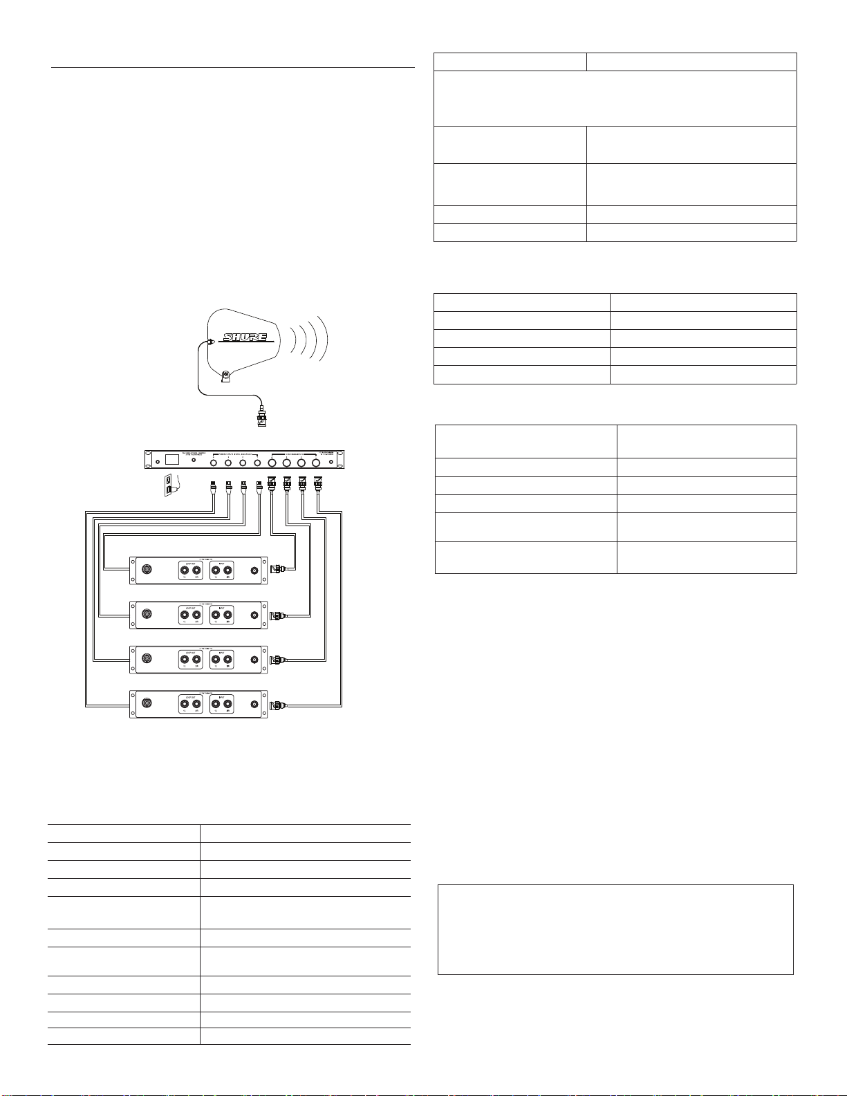
4-TO-1 COMBINING FOR PSM TRANSMITTERS
1. Using the supplied BNC-BNC cables, connect the Antenna Output
of each transmitter to the Antenna Inputs of the PA421A (See
Figure 2).
2. Attach an antenna to the MAIN Out of PA421A. For wideband
applications, use PA805SWB directional antenna (Figure 2).
3. Connect the PA421A to a power outlet using one of the supplied
power cables. The PA421A contains a universal power supply to
operate anywhere in the world.
4. If you have a Shure PSM system that has the same power input
connectors as the PA421A power outputs, such as the PSM900,
connect the PSM system to the PA421A via the supplied power
cables (see figure 2). This replaces the need for an external power
supply.
NOTE: The PA421A supplied power is 15 V and up to 660 mA.
®
PA80 5WB
Figure 2
NOTE: When the PA421A is powered on, the input signal
indicators (1-4) on the front panel will illuminate if an active
transmitter is connected to the corresponding input (1-4) on the
back panel (Figure 2).
SPECIFICATIONS
RF Carrier Frequency Range 470-952 MHz
System Gain +0/-5 dB
Input AC Line Voltage 100-240 Vac, 50/60 Hz
Maximum Input Line Power 1.2A 80W
Maximum Current Drain 0.42-1.0 Amperes
(Amperes = 100 VA/Input AC Line Voltage)
Maximum RF Input Power 24 dBm (250 mW) per channel
Input Signal Indicator
Threshold +4 dBm (2.5 mW), +2 dBm (1.6 mW) typical
Impedance 50 Ωnominal
Operating Temperature Range 0°F (-18°C) to +145°F (+63°C)
NOTE: Electrical safety approval is based on a maximum ambient
temperature of 30°C.
Overall Dimensions 43.4 mm high x 398.8 mm wide x331.5 mm
deep (1 11/16 in. H x 15 11/16 in. W x
13 1/2 in. D)
Net Weight 4.53 Kg
(10 lbs unpackaged, without power and
RF cables)
Input/Output Connector Type BNC-type 4 input, 1 output ACTIVE
Power Outputs (4) 15 VDC, 660 mA each
FURNISHED ACCESSORIES
(4) 2 ft. Coaxial Cable (RG58C/U) UA802
(4) 2 ft. Output Power Cable 95B8420
120 VAC Power Line Cord 95A8389
230 VAC Power Line Cord 95A8247
240 VAC Power Line Cord (U.K.) 95A8713
OPTIONAL ACCESSORIES
Wideband Unidirectional Antenna
(470-952 MHz)
PA805SWB
10 ft. Coaxial Cable (RG-8X/U) PA725
25 ft. Coaxial Cable (RG-8X/U) UA825
50 ft. Coaxial Cable (RG-8X/U) UA850
Wide Band Omnidirectional Antenna
(470-1100 MHz) UA860SWB
Helical Antenna HA-8089 (480-900 MHz)
HA-8241(944-952 MHz)
AC Power
PSM Transmitters
50Ω BNC
CERTIFICATIONS
PA421A: Certified to FCC Part 74 (FCC ID No. DD4PA421A).
Certified in Canada by IC to RSS-123 AND RSS-102 (Certification No.
IC: 616A-PA421A). UL LISTED to UL60065, 7th Edition and cUL
LISTED to CAN/CSA E60065-00. Meets the Essential Requirements of
the European R&TTE Directive 99/5/EC, eligible to bear CE mark. Meets
EMC requirements of EN 301 489 Parts 1 and 9 and is GS-Certified to EN
EN60065, 7th Edition. Conforms to Australian EMC requirements, eleigible
to bear C-Tick mark (N108).
LICENSING
Changes or modifications not expressly approved by Shure Incorporated
could void your authority to operate the equipment. Licensing of Shure
wireless microphone equipment is the user’s responsibility, and licensability
depends on the user’s classification and application, and on the selected
frequency. Shure strongly urges the user to contact the appropriate
telecommunications authority concerning proper licensing, and before
choosing and ordering frequencies.
THIS RADIO EQUIPMENT IS INTENDED FOR USE IN PROFESSIONAL
ENTERTAINMENT AND SIMILAR APPLICATIONS.
NOTE
THIS EQUIPMENT MAY BE CAPABLE OF OPERATING ON SOME
FREQUENCIES NOT AUTHORIZED IN YOUR REGION. PLEASE
CONTACT YOUR NATIONAL AUTHORITY TO OBTAIN INFORMATION
ON AUTHORIZED FREQUENCIES FOR WIRELESS MICROPHONE
PRODUCTS IN YOUR REGION.
Licensing: Note that a ministerial license to operate this equipment may
be required in certain areas. Consult your national authority for possible
requirements.
165VA
AC Current Max
Power Max
Apparent Power Max
1.4A
82W
170VA
www.shure.com ©2010 Shure Incorporated
Europe, Middle East, Africa:
Shure Europe GmbH
Wannenäckestr. 28,
74078 Heilbronn, Germany
Phone: 49-7131-72140
Fax: 49-7131-721414
Email: [email protected]
Asia, Pacific:
Shure Asia Limited
22/F, 625 King’s Road
North Point, Island East
Hong Kong
Phone: 852-2893-4290
Fax: 852-2893-4055
Email: [email protected]
United States, Canada, Latin
America, Caribbean:
Shure Incorporated
5800 West Touhy Avenue
Niles, IL 60714-4608 USA
Phone: 847-600-2000
Fax: 847-600-1212 (USA)
Fax: 847-600-6446
Email: [email protected]

Other Shure Network Hardware manuals

Shure ANI22 User manual

Shure

Shure ANI22 User manual

Shure AXIENT AXT630 User manual

Shure

Shure AXIENT AXT630 User manual

Shure AD600 User manual

Shure

Shure AD600 User manual

Shure ANIUSB-Matrix User manual

Shure

Shure ANIUSB-Matrix User manual

Shure AD600-DC User manual

Shure

Shure AD600-DC User manual

Popular Network Hardware manuals by other brands

Safety Vision ROADRECORDER 8000 NVR user guide

Safety Vision

Safety Vision ROADRECORDER 8000 NVR user guide

Lorex N863P Series Quick setup guide

Lorex

Lorex N863P Series Quick setup guide

Super Circuits DMR 1 user guide

Super Circuits

Super Circuits DMR 1 user guide

DINOX NVR-4004 Quick operation guide

DINOX

DINOX NVR-4004 Quick operation guide

Lorex LNR100 SERIES instruction manual

Lorex

Lorex LNR100 SERIES instruction manual

Lanner EAI-I130 user manual

Lanner

Lanner EAI-I130 user manual

IBM DualPort TR Controller NetFlex-2 Quickspecs

IBM

IBM DualPort TR Controller NetFlex-2 Quickspecs

Honeywell Notifier NFN-GW-EM-3 Installation and operation manual

Honeywell

Honeywell Notifier NFN-GW-EM-3 Installation and operation manual

Monacor NVR-104 SET Short instruction manual

Monacor

Monacor NVR-104 SET Short instruction manual

AVE Vsi-Pro Max instruction manual

AVE

AVE Vsi-Pro Max instruction manual

Omron DEVICENET - Operation manual

Omron

Omron DEVICENET - Operation manual

Draytek Vigor2927 Series quick start guide

Draytek

Draytek Vigor2927 Series quick start guide

Ubiquiti UF-AE quick start guide

Ubiquiti

Ubiquiti UF-AE quick start guide

TECHVIEW QV-3162 user manual

TECHVIEW

TECHVIEW QV-3162 user manual

Ruckus Wireless ZoneFlex7731 802.11n installation guide

Ruckus Wireless

Ruckus Wireless ZoneFlex7731 802.11n installation guide

Tandberg Data RDX QuikStation 4 Quick start guides

Tandberg Data

Tandberg Data RDX QuikStation 4 Quick start guides

General DataComm OCM-2000 Installation & operation manual

General DataComm

General DataComm OCM-2000 Installation & operation manual

urmet domus 1093 Series User manual/instructions

urmet domus

urmet domus 1093 Series User manual/instructions

manuals.online logo
manuals.online logoBrands
  • About & Mission
  • Contact us
  • Privacy Policy
  • Terms and Conditions

Copyright 2025 Manuals.Online. All Rights Reserved.