2
English –
INTRODUCTION
DATA
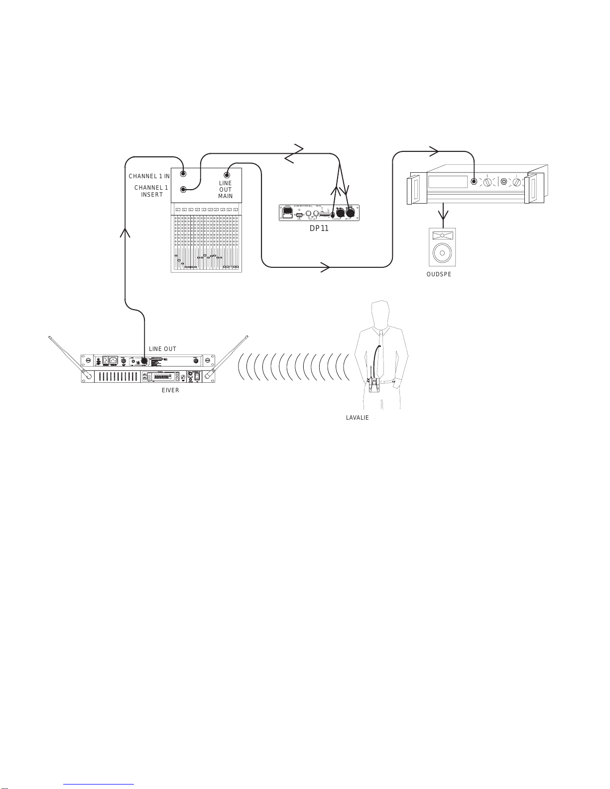
The Shure Model DP11EQ is a single-channel, digital signal processor that combines a
comprehensive dynamics processor, two parametric equalizers, and a delay in a single, half-rack
enclosure. The DP11EQ can function as a gate, expander, Automatic Gain Control (AGC) leveler,
compressor, limiter, and no overshoot peak limiter. All of these features are accessed via the
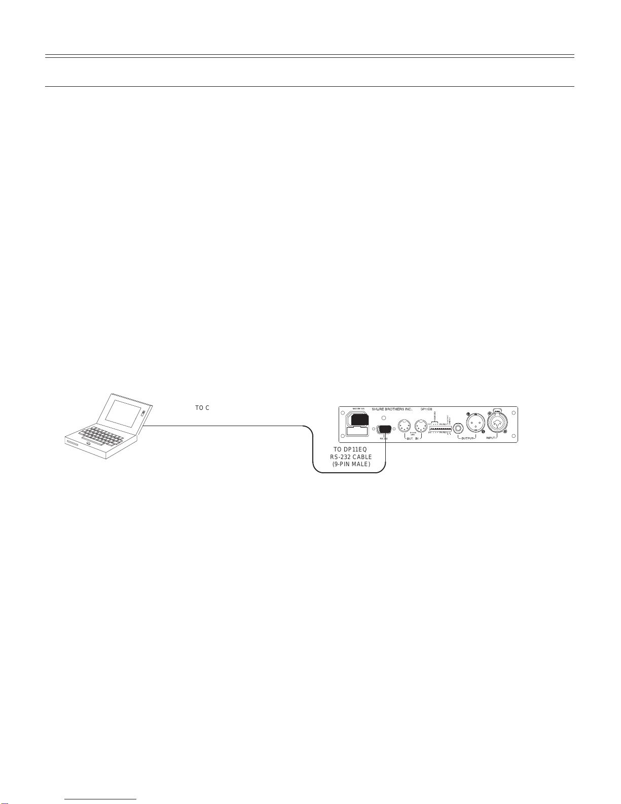
supplied Windows* software. You can connect a computer to set up the unit in a sound system, then
remove the computer so no one can tamper with the settings when the unit is left unattended. The
DP11EQ is designed for installed sound reinforcement applications: theater, conference rooms,
meeting halls, houses of worship, etc.
Hardware Features
S
Crystal* 20-bit A/D and D/A converters
(Analog-to-Digital, Digital-to-Analog) for 104 dB
dynamic range.
S
48 kHz sampling rate for flat response to 20 kHz.
S
Half-rack space chassis allows rack mounting of
one or two units in a single rack space with no
sagging or bending.
S
Shure Link Interface allows multiple units to be
programmed with a single computer.
S
Independently driven, cross-coupled, balanced
1
/
4
-inch and XLR outputs. Can be used with
balanced or unbalanced inputs.
S
Electronically balanced input with combination
1
/
4
-inch and XLR connector. Can be used with
balanced or unbalanced outputs.
S
No internal batteries. Settings and DSP program
stored in internal EEPROM.
S
+4 dBu/–10 dBV DIP-switch-selectable input and
output levels.
S
80 MHz Motorola* DSP56009 processor engine
with full 24-bit internal processing.
S
RS-232 interface for external computer control
and firmware updates.
S
Internal linear power supply eliminates the need
for a cumbersome external power supply.
S
Solid state bypass eliminates unreliable
mechanical relays and switches.
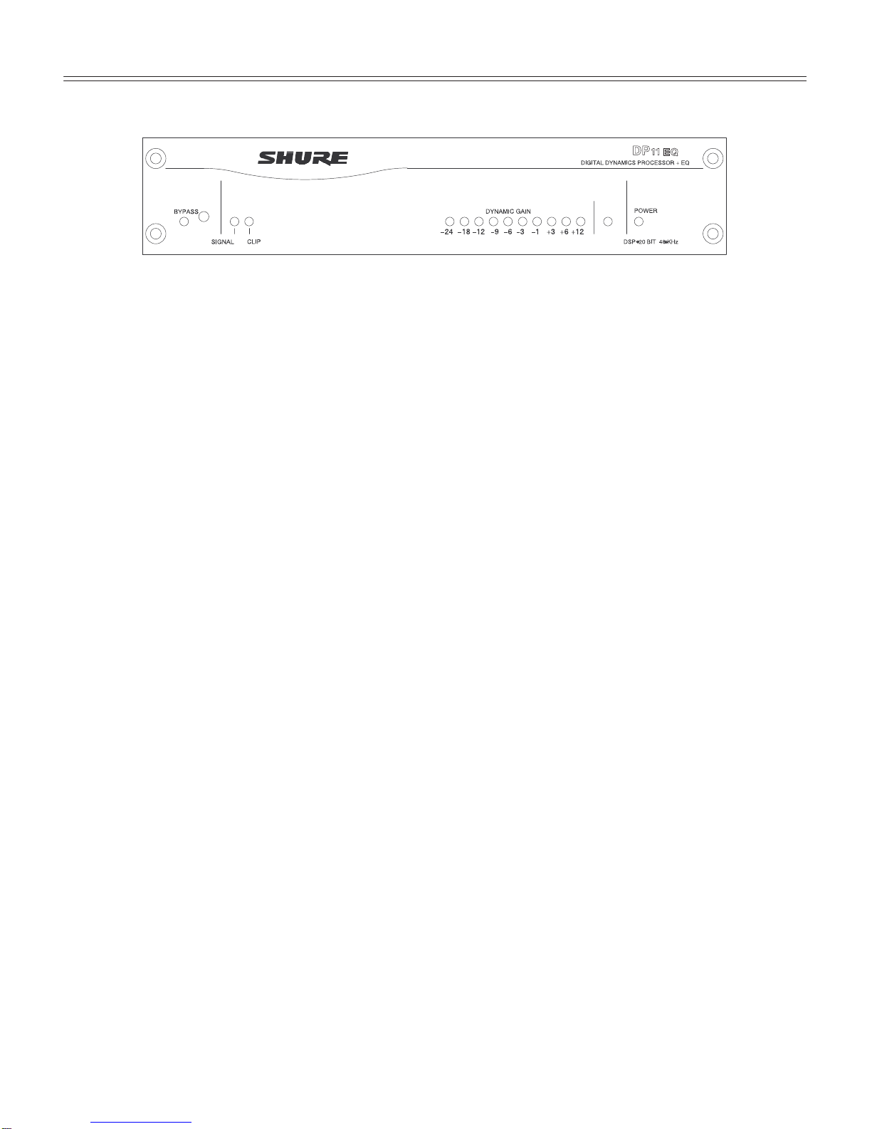
S
A SIGNAL presence and a CLIP indicator
S
DYNAMIC GAIN meter.
S
Shure Link connectors for networking to other
Shure Link devices, such as the models
DFR11EQ and UA888.
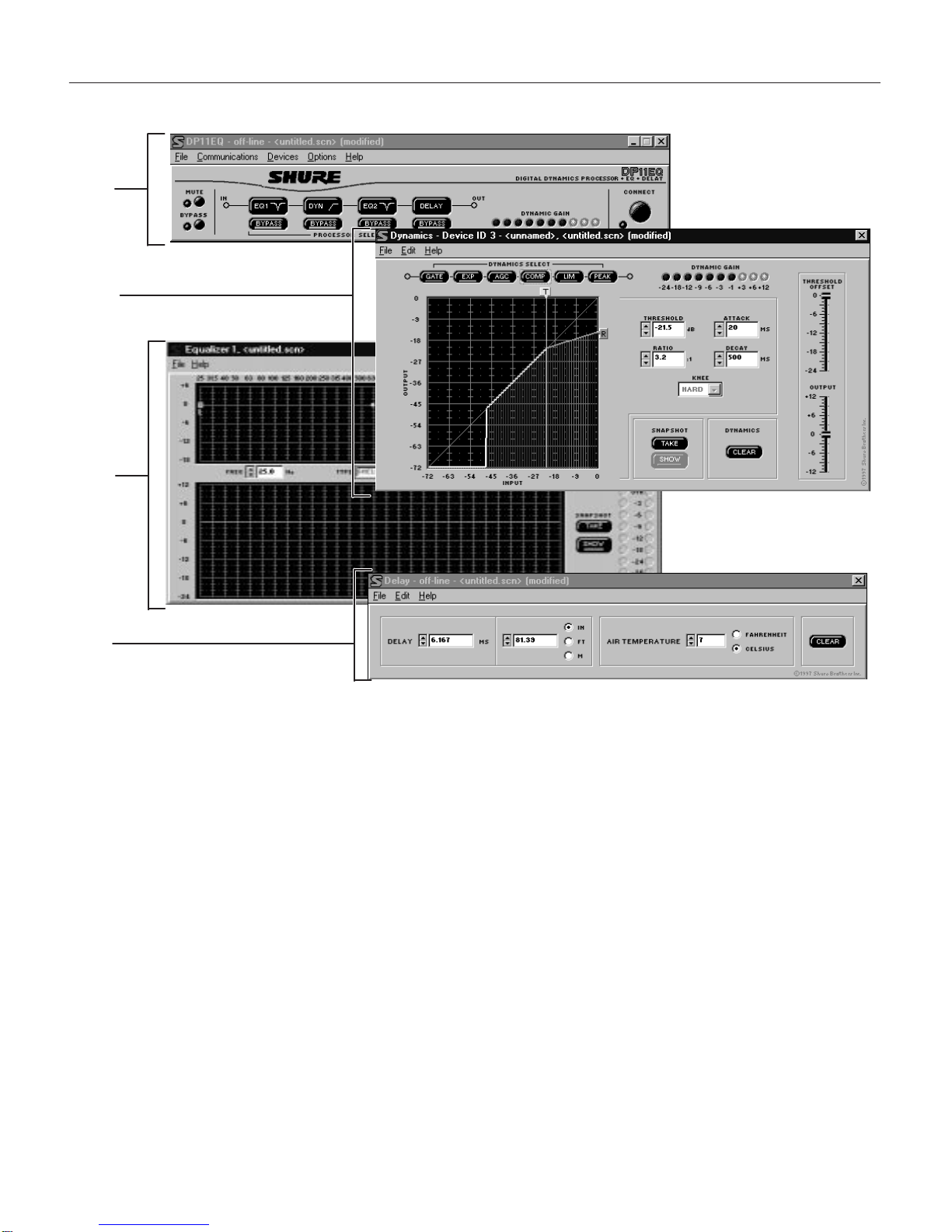
Software Features
S
Four (4) processing blocks: pre-dynamics
equalizer (EQ1), dynamics (DYN), post-dynamics
(EQ2), and Delay.
S
The dynamics processor functions as a Gate,
Expander, AGC Leveler, Compressor, Limiter, and
No Overshoot Peak Limiter.
S
The parametric equalizer offers up to 10 filters
with adjustable frequency, up to 6 dB of boost or
–18 dB of cut per filter,
1
/
40
to 2 octave bandwidth.
S
Response Viewing. The dynamics and equalizer
windows each have a viewer which shows the
effect of the process on the signal.
S
Up to 1.3 seconds of Digital Delay with
temperature compensation option. Displayed in
time and distance.
S
Digitally-controlled signal polarity inverting for
equipment that inverts balanced signals.
S
Front panel lockout control to prevent tampering.
S
Storage of multiple scenes to floppy or hard disk.