SI SUITE XVI User manual

SUITE XVI
Installation Instructions
DOC.#400166 v.1.2 25 May 2022

Thank you for purchasing an SI product. If you have any questions or need any assistance with your Suite XVI, we would
love to help you.
Technical Support: 512.832.6939
Hours of Support: 7:30am – 5pm CST
screeninnovations.com
Once the install is complete, go to https://support.screeninnovations.com/accessories/suitexvi/, or
scan the QR code for the programming manual or other resources.

CONTENTS
Introduction. . . . . . . . . . . . . . . . . . . . . . . . . . . . . . . . . . . . . . . . . . . . . . . . . . . . . . . . . . . . . . . . . . . . . . . . . . . . . . . . . . . . . . . . . .4
Initial Considerations . . . . . . . . . . . . . . . . . . . . . . . . . . . . . . . . . . . . . . . . . . . . . . . . . . . . . . . . . . . . . . . . . . . . . . . . . . . . . . . .5
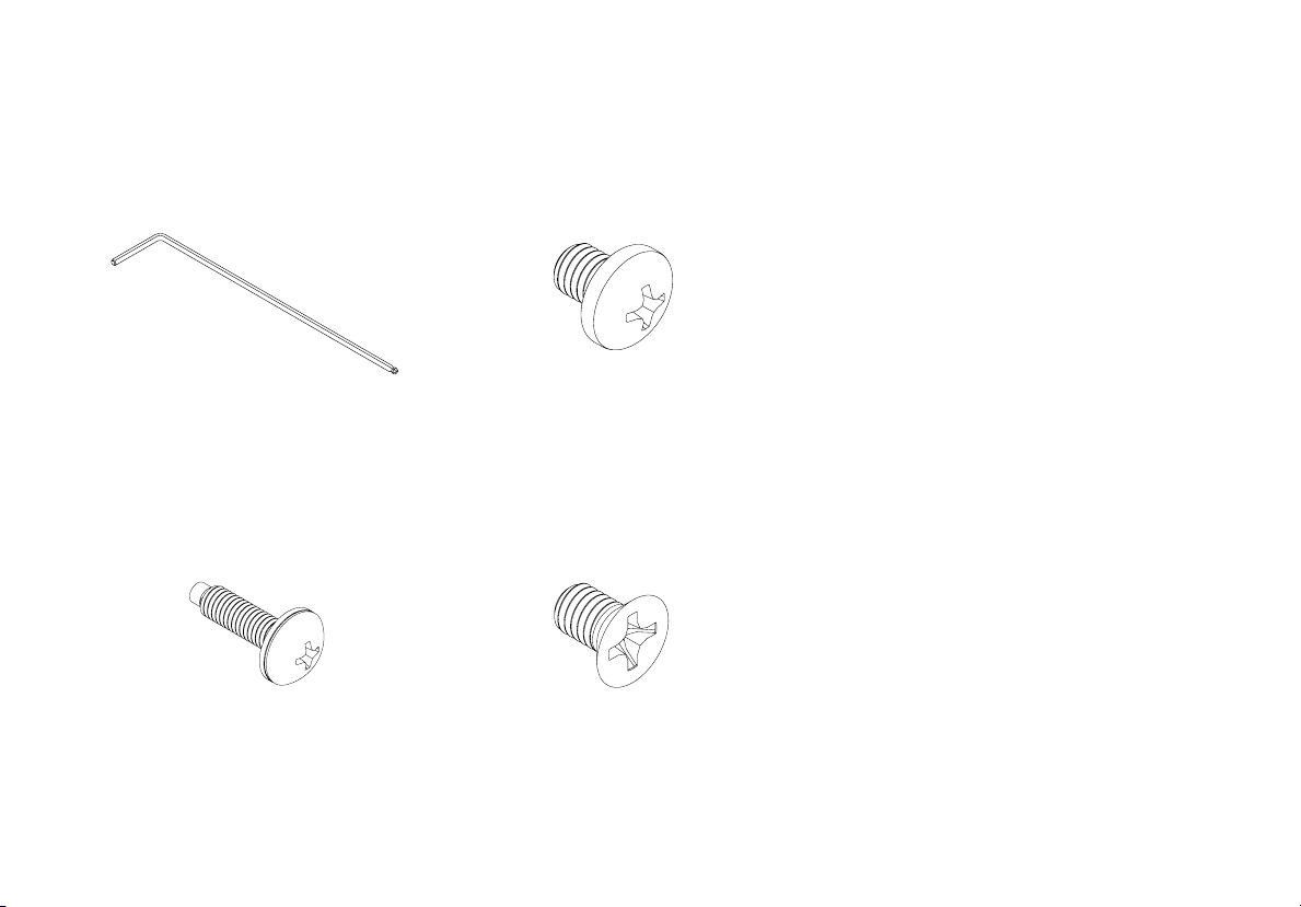
Parts in the Box . . . . . . . . . . . . . . . . . . . . . . . . . . . . . . . . . . . . . . . . . . . . . . . . . . . . . . . . . . . . . . . . . . . . . . . . . . . . . . . . . . . 6 - 7
Installation . . . . . . . . . . . . . . . . . . . . . . . . . . . . . . . . . . . . . . . . . . . . . . . . . . . . . . . . . . . . . . . . . . . . . . . . . . . . . . . . . . . . .10 - 15
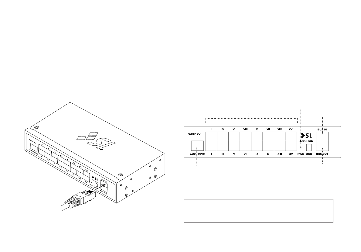
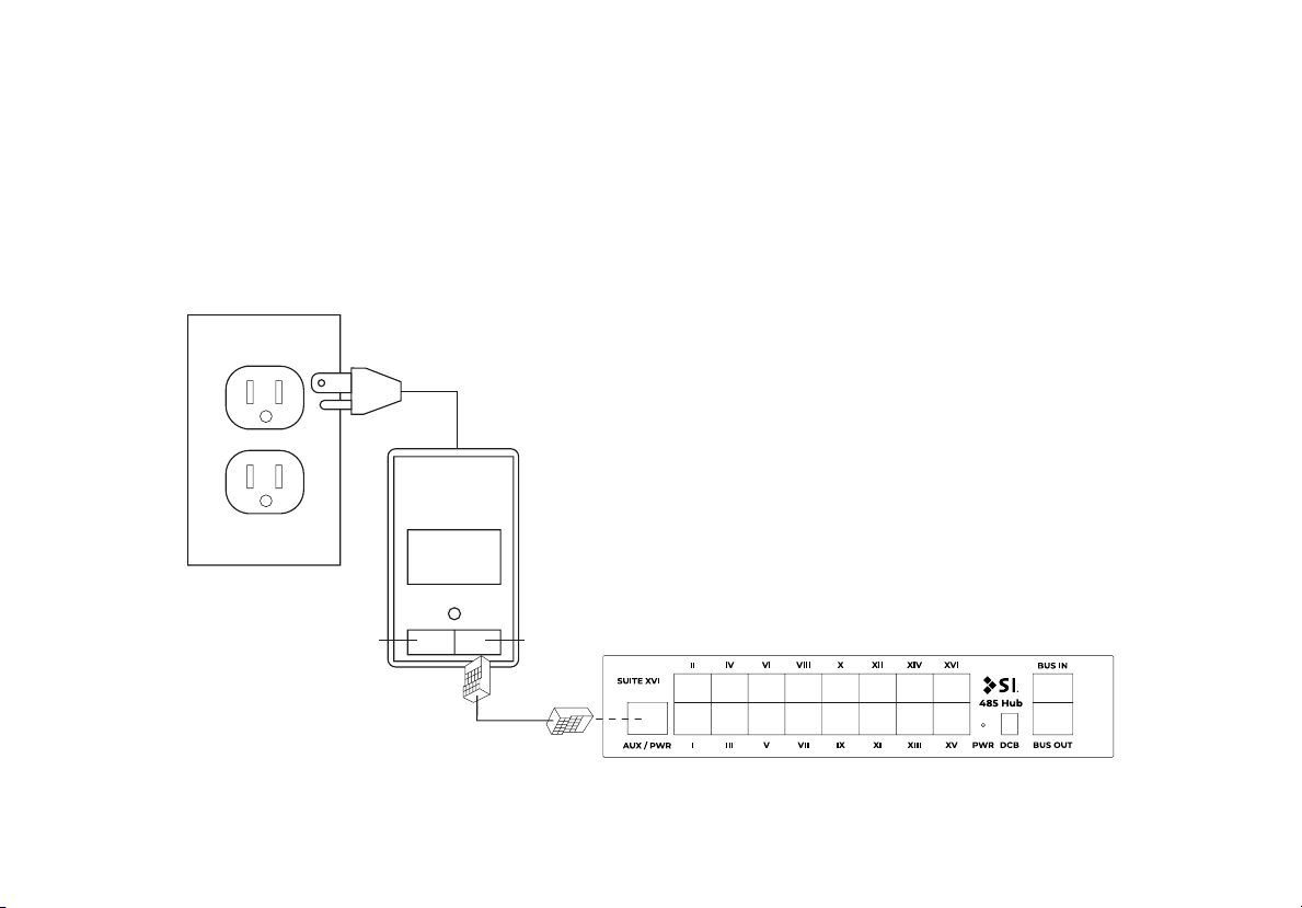
Connections . . . . . . . . . . . . . . . . . . . . . . . . . . . . . . . . . . . . . . . . . . . . . . . . . . . . . . . . . . . . . . . . . . . . . . . . . . . . . . . . . 8 - 10
LED Operations . . . . . . . . . . . . . . . . . . . . . . . . . . . . . . . . . . . . . . . . . . . . . . . . . . . . . . . . . . . . . . . . . . . . . . . . . . . . . . . . .11
Button Operations . . . . . . . . . . . . . . . . . . . . . . . . . . . . . . . . . . . . . . . . . . . . . . . . . . . . . . . . . . . . . . . . . . . . . . . . . . . . . . .12
Rack Mounting . . . . . . . . . . . . . . . . . . . . . . . . . . . . . . . . . . . . . . . . . . . . . . . . . . . . . . . . . . . . . . . . . . . . . . . . . . . . . . . . .13 - 19
Din Rail Mounting . . . . . . . . . . . . . . . . . . . . . . . . . . . . . . . . . . . . . . . . . . . . . . . . . . . . . . . . . . . . . . . . . . . . . . . . . . . . . . .20 - 22
Structured Wire Box Mounting . . . . . . . . . . . . . . . . . . . . . . . . . . . . . . . . . . . . . . . . . . . . . . . . . . . . . . . . . . . . . . . . . . . .23 - 24
Additional Accessories . . . . . . . . . . . . . . . . . . . . . . . . . . . . . . . . . . . . . . . . . . . . . . . . . . . . . . . . . . . . . . . . . . . . . . . . . . . . . .25
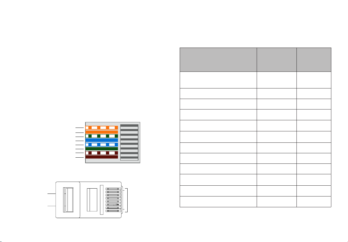
Troubleshooting Ethernet . . . . . . . . . . . . . . . . . . . . . . . . . . . . . . . . . . . . . . . . . . . . . . . . . . . . . . . . . . . . . . . . . . . . . . . . . . . .26

4
INTRODUCTION - Suite XVI
• (16) 485 device ports
• (1) 485 Bus In port
• (1) 485 Bus Out port
• (1) 485 Auxillary/Power input port
• Versatile mounting options
• Completely solid state, no moving parts
• Unit remains at room temperature (does not emit heat)
• Selectable 485 DC BIAS
• Includes bus segment status LEDs for:
- Power
- Communication
- End of line notication
Features
SUITE XVI is a 485 Data Hub that can support up to sixteen 485 devices such as 485 keypads, 485 Wireless
controllers, 485 GPIO interfaces, and 485 AC power motors. This product can work directly with JANUS, TRO.Y,
and other 485 devices and may be powered by the 485 BUS input or an optional external bus power supply.

5
INITIAL CONSIDERATIONS
Thank you for your purchase of Suite XVI.
This is designed to be installed indoors, Rack or Din mounted.
Suite XVI has sixteen (16) 485 ports. The two main applications include 485 devices such as keypads and 485
AC power motors.
See the gure showing TRO.Y connected to two Suite XVI data hubs, connected to 16 keypads and 16 AC
powered shades.

6
PARTS IN THE BOX
Suite XVI
Universal Rack Ears (2)
Rack Mount Fascia
Universal DIN Rail Bracket (2)
Universal DIN Rail
Long Rack Ear

7
DIN Rail Screws (2)
Universal Mounting
Screws (10)
Rack Mount Screws (4)
1.5 mm Hex Tool

8
485 Ports (1–16) Bus In
Bus Out
Auxiliary Power
Input
INSTALLATION - CONNECTIONS
Connecting Power
SUITE XVI is powered using the power available on the 485 bus IN connection. When using this data hub with
other devices, check the spec sheet for the device to determine how many power units the device can power.
If the device does not have suitable power for all devices connected to the hub, then you can add a 485 bus
power supply to the AUX power input
Connections
Bus In
DC Bias
Power
LED
Note: Line Bus protection from powered devices
connected to device ports

9
INSTALLATION - CONNECTIONS
Connecting Suite XVI
Suite XVI offers the ability to connect up to sixteen (16)
485 devices or AC motors, using CAT5e/6 cable.
If connecting more than sixteen devices, add additional
Suite XVI via the Bus Out and Bus In. Attention must
be paid when adding additional Suite XVI hubs as
additional auxillary Bus power may need to be applied.
Common 485 Bus Power units
SDN (485) connection
Data +(WHT/ ORG)
Data - (ORG)
N/A (WHT/ GRN)
N/A (GRN)
Power + (BLUE)
Ground - (WHT/ BRWN)
Ground - (BRWN)
Power + (WHT/ BLUE)
All 485 ports
Upto 200' max. CAT 5e or better
Pin 1
Pin 8
485 Bus Device Bus Power
Units (BPU)
provided
Bus Power
Units (BPU)
consumes
Janus (BPU provided only on ports
1–8)
100 0
TRO.Y (per port) 16 0
UAI+/SI.FI 0/40 1/0
Bus Power Supply - #18224400 80 0
Suite XVI N/A 1
Suite XVI (DCB enabled) N/A 1.5
Keypad/Decoset N/A 1
RTS Receiver N/A 1
Fontus N/A 1
AC Motors 4 0
MOAB N/A 2
CAT 5 (per 100 feet) N/A 0.25

10
INSTALLATION - CONNECTIONS
Utilizing Auxiliary Power Input
When an Auxiliary Bus Power is connected, it takes prescedent over any power on the Bus In.
Data Pass-
through Input
Power/Data
Output
Bus Power
Supply
Stub length must not exceed 200’

11
Port Left LED OFF
(Yellow)
Left LED ON
(Yellow)
Left LED
blinking
Right LED
OFF (Green)
Right LED ON
(Green)
Right LED Flashing
(Green)
Bus In N/A N/A N/A N/A Bus Idle (bus
connected) With Bus data activity
Bus Out Bus Idle (bus
connected)
End of Bus Line
(not connected)
N/A Bus Idle (bus
connected) N/A With Bus data activity
Aux.
Power
N/A Aux. Power con-
nected (GREEN) N/A N/A N/A With Bus data activity
Main
Power
No power on Bus
(RED)
Power on Bus
(RED) N/A N/A N/A N/A
INSTALLATION - LED OPERATION
LED information table

12
DCBias FUNCTIONALITY:
Note: Use a thin tool such as a paper clip.
Switch 1 - Enables DCBias for 485 - A
Switch 2 - Enables DCBias for 485 - B
Note: DCBias should only be used for
extremely long or very noisy Bus lines.
INSTALLATION - DC BIAS OPERATION

13
Screw Hole Locations
Suite XVI can be mounted in various ways using the ten (10) screw hole locations shown
below.
RACK MOUNTING
Janus and Suite XVI share the same mounting features and accessories; there are
innite ways to install them together or seperately.
Several Din Rail screw
locations

14
RACK MOUNTING
Using Universal Rack Ear
The symmetrical hole pattern of the Suite XVI Universal Rack Ear allows these multi-functional brackets to be
mounted on either side of Suite XVI in any orientation. This makes it possible to mount Suite XVI to virtually any
surface, in multiple positions.

15
1. Half Rack
Suite XVI can be mounted in a standard half rack using two Universal Rack Ears.
9.73” (247mm)
RACK MOUNTING
Note: Half Rack hole spacing must
be 9.73”(247mm).

16
2a. Full Rack (Single Suite XVI Unit)
A single Suite XVI unit can be mounted in a standard 19” rack using one Universal Rack Ear and one Long Rack
Ear.

17

18
2b. Mounting with Suite XVI Full Rack
Two Suite XVI/Janus units can be coupled together and mounted in a standard 19” rack. Follow the steps on the
following spread for installation:
a. Using two (2) of the included DIN Rail Screws,
install the DIN Rail onto the rst TRO.Y unit.
b. Using three (3) Rack Ear screws each (included),
install the two DIN Rail Brackets on the opposite
side of the second TRO.Y unit.
c. While holding both TRO.Y units, slide the DIN Rail
through both DIN Rail brackets. Then, tighten both
set screws using the provided 1.5mm hex tool.
d. Slide the Rack Mount Fascia over the exposed
DIN Rail bracket on the desired front face of the
combined unit. Fasten the fascia down with two
(2) Rack Ear Screws on the top and bottom.
e. Finally, fasten one Rack Ear to each TRO.Y unit
using three (3) Rack Ear screws each.
Note: When combining a Suite XVI and
Janus, use the DIN rail included with Janus.

19
Rack Mount Fascia
DIN Rail Bracket
Rack Ear
DIN Rail
Note: Suite XVI and Janus are
100% compatible in mounting.

20
Screw Hole Locations
Suite XVI is available in both plenum and non-plenum options. If mounting in a plenum air space, ensure you
have purchased a plenum-rated Suite XVI kit.
Suite XVI can be mounted in various ways using ten (10) screw hole locations.
DIN RAIL MOUNTING
Several Din Rail screw
locations
Table of contents
Other SI Switch manuals
Popular Switch manuals by other brands

Gianni Industries
Gianni Industries CP-15 Series Specifications

Hama
Hama USB 3.0 Hub 1:4 Operating instruction

UTEPO
UTEPO UTP3-GSW1604TS-P200 user manual

D-Link
D-Link DWL-P200 Quick installation guide

ZyXEL Communications
ZyXEL Communications GS1100 Series user guide

Hirschmann
Hirschmann MACH 4000 Series Reference manual